Form/Formulaire n°/Formulario n.° 97641 Rev. A 04.25.17
3
Part No.
N° de pièce
Pieza n.°
97603
Made in the U.S.A.
Fabriqué aux É.-U.
Hecho en EE. UU
P.O. Box 1285
Ann Arbor, MI 48106
www.thetford.com
Questions?/Des questions?/¿Preguntas? 1-800-543-1219
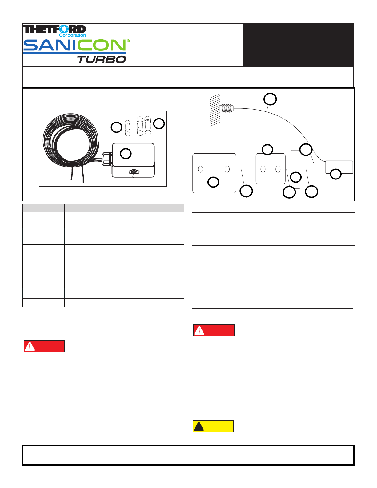
Piezas: K1 - K3
Nueva pieza Ref. Descripción
K1 K1 (1x) Caja de interruptor
K1.1 Cable rojo
K2 K2 (2x) Conectores, 10-12 AWG
K3 K3 (1x) Conector, 14-16 AWG
NI A Fuente de alimentación del vehículo de recreo
A.1 Cable rojo de la fuente de alimentación
NI B Bomba
B.1 Cable negro de la bomba
B.2 Cable azul de la bomba
B.3 Cable negro de la bomba - negativo
(cable largo)
NI C Portafusibles / Fusible de 35 A
NI NO SE INCLUYE (solo para referencia).
Juego de caja de interruptor
B
B.1
K1
K1.1
A.1
C
A
B.3
B.2
Herramientas necesarias:
■Cortador/pelador de cables
■Pinza para prensar cables
■Herramienta de calentamiento
Thetford Corporation recomienda que las
labores de servicio de este producto estén a
cargo exclusivamente de técnicos capacitados
ycalicados,yquelaslaboreseléctricasy
de plomería estén a cargo exclusivamente de
personaltécnicocerticado.Sedebecumplir
con los códigos y permisos municipales.
Thetford Corporation no admite ninguna
obligación o responsabilidad por daño al equipo,
lesiones o muerte que pudieran ser causados
por la instalación, la reparación o el manejo
incorrectos de este sistema.
Antes de continuar, compruebe que se ha
desconectado la electricidad.
La caja de interruptor es apta únicamente para
uso en interiores y es imperativo protegerla
contra el agua.
ATTENTION
!
PREPARAR
■Descargue todos los residuos de los tanques de retención.
■Cierre todas las válvulas de vaciado.
RETIRAR LA PIEZA
EMPLEAR LAS PIEZAS USADAS:
1. Ubicar A; desconectar el cable rojo positivo A.1.
2. Dejar una amplia longitud del cable cortando K1.1 y B.1
y B.2 cerca de K1; desechar K1 (antigua).
REEMPLAZAR LA PIEZA
EMPLEAR LAS PIEZAS NUEVAS:
Cubra los cables con un revestimiento de
cables (no suministrado) para protegerlos
contra el agua y objetos extraños.
1. Fijar K1 en el compartimiento del vehículo de recreo.
2. Para conectar K1:
• Con K2, conectar B.1 y K1.1.
• Con K3, conectar B.2.
3. Para sellar los conectores termocontráctiles, calentar los
conectores tras conectar los cables. Se deben conectar los
cables adicionales que sean necesarios.
4. Volver a conectar A.1 con A.
5. Encender K1;vericarquehayaunvoltajede12V
en el motor.
Una instalación incorrecta podría dañar el
motororeducirlaecienciadelabomba.
ATTENTION
!
!
ATTENTION
!
ATTENTION
!
K1
K2
K1