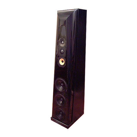
Thiel Coherent Source CS3.7 Manual

Supplemental
Technical Information
for model
THIEL CS3.7
Coherent Source
®Loudspeaker
This paper contains only information specific to the CS3.7 speaker system.
It is intended to supplement the general technical information paper which
explains our engineering philosophy, goals and techniques.
This advance copy contains only technical information about the unique
midrange driver used in the CS3.7.
PRELIMINARY

NEW MIDRANGE DRIVER
The most important reason for the improved sonic
performance of the CS3.7 is its new midrange driver. This driver
was developed to solve two problems that otherwise exist in
midrange performance – diaphragm resonances and tweeter
interference. Before explaining the new solutions I will review the
problems that have been addressed by the new design.
Review of the Basic Problem
Drivers produce sound by moving their diaphragms in and out
following the waveform of the input signal. Ideally, the
diaphragm moves as a whole, every point moving the same as
every other point. This is called “piston” movement. All
diaphragms achieve piston operation at low frequencies but as the
frequency increases a point is reached where the movement of the
diaphragm “breaks-up”, with different parts of the diaphragm
moving independently of other parts. At these higher frequencies
the diaphragm is internally resonating, meaning that it is
oscillating of its own accord. These resonances cause the sonic
output of the driver to “ring” at these frequencies, producing sonic
output when it’s not supposed to. The resonances also cause some
frequencies to be exaggerated and others to be diminished,
changing the tonal character of the sounds being reproduced.
Previous state-of-the-art
The approach that THIEL has pursued to minimize the effects
of diaphragm breakup is to develop diaphragms that are stiff
enough to maintain piston operation throughout their primary
operating range. This is achieved by using aluminum as the
material, careful engineering of the diaphragm’s shape,
laminating the aluminum with styrene foam to stiffen and damp
the diaphragm and the use of larger diameter voice coils. These
techniques can result in diaphragms that have a much greater
range of frequencies reproduced under piston operation. An
example of such a driver is the THIEL CS6 midrange whose
response is shown here.
This
driver
exhibits
exceptionally
good
response,
with piston
operation
being
maintained to
beyond 5 kHz, almost an octave above its primary operating range
of 3 kHz. In addition, the resonant behavior that is exhibited at
high frequencies is much simpler than usual, basically consisting
of only one resonance below 10 kHz. This simplicity of resonant
behavior provides the advantage of making it feasible to
electrically correct and compensate for the dominant resonance.
The response exhibited after such electrical correction is graphed
here. This is
exceptionally
wide band
and
resonant-free
operation.
The Remainder
However, it is still true that what imperfections remain in the
midrange performance are primarily due to the residual effects of
the diaphragm resonances that do exist. And, therefore, to achieve
even better performance requires further improvement in
diaphragm behavior.
An Additional Problem
There is an additional problem concerning the midrange driver
that we wish to address. This second problem exists only as a by-
product of solving another problem (this type of situation is not
uncommon in loudspeaker design). The “other” problem in this
case is that of time coherence. Time coherence describes that all
component harmonics of every sound reach the listener’s ears at
the same time and is achieved by positioning the drivers so that
each is the same distance from the listener’s ears. THIEL uses two
techniques, singly or in combination, to achieve time coherence in
all our products. One technique is to mount the drivers on a sloping
baffle and adjust the angle of the slope and the driver spacing to
achieve coherence. This can work well for floor standing speakers,
especially at lower frequencies. But it cannot work for non floor
standing speakers where the location of the speaker is unknown,
and in any case the accuracy of the results at high frequencies
becomes somewhat dependant on the listener’s position. For this
reason, a better technique for time coherence at higher frequencies
is to mount the tweeter coincidently (both coaxially and
coplanarly) with the midrange driver. Such mounting ensures that
the sound from both drivers always reach the listener at exactly the
same time, regardless of where the speaker is placed or where the
listener is. Such mounting also completely eliminates any “lobing”
in the speaker’s radiation pattern.
Our “additional problem” is that such coincident mounting of
the tweeter in the center of the midrange driver alters the tweeter’s
output due to reflections and diffractions from the midrange
diaphragm. This effect is illustrated by the two graphs below. The
first shows the tweeter response as being extremely uniform and
free of resonances to beyond audibility. The second shows the
response when mounted in a normal midrange driver. The
detrimental alterations are clear. Even after electrical correction the
response leaves room for improvement.
Large distance from voice coil
to edge of diaphragm allows
diaphragm resonances at
frequencies lower than desirable.
Tweeter in the recessed shape
of the midrange cone causes
diffraction/ reflection problems.
voice coil
Midrange diaphragm
relies on resessed,
“cone” shape for strength.
Tweeter coaxially mounted in conventional midrange
10
100
5
0
-5
5
p
1kHz 10kHz
Response of CS6 midrange driver
10
100
5
0
-5
5
1kHz 10kHz
Response of CS6 midrange driver with electrical correction
100
5
0
-5
5
Amplitude — dB
1kHz 10kHz
Response of CS3.7 tweeter
100
5
0
-5
5
Amplitude — dB
1kHz 10kHz
Response of CS3.7 tweeter coaxially mounted in standard midrange

A Solution
What is needed to solve both these problems simultaneously
is a midrange diaphragm that is ten times as stiff per weight as the
previous extremely stiff composite diaphragm while also being
flat rather than cone shaped. But these requirements work against
each other. The flatter the diaphragm’s shape the weaker it
becomes. And even with a normal shape, how can we increase the
stiffness this dramatically? Even exotic materials like beryllium
are not nearly that stiff, even in the traditional cone shape.
The solution we developed relies on geometry rather than a
more exotic material to achieve both goals. There are several
elements to the design:
• A large voice
coil is used so that
its force is applied
at a point equally
spaced between the
diaphragm’s inner
and outer edges,
rather than at the
inner edge. This
reduces the
distance from the
driving point to the
diaphragm’s edge
and therefore
greatly increases
stiffness.
• Reliance on
the great stiffness in the circular direction of the voice coil
former’s cylindrical shape so that the diaphragm itself is only
required to provide stiffness in the radial direction. This allows
the diaphragm to be formed with shapes that greatly increase
strength in the direction from the center to the edge, even if
decreasing strength around the circumference.
• An undulating, radially ribbed contour is used for the
diaphragm which provides light weight and great stiffness in the
radial direction while still maintaining a basically flat shape.
CS3.7 midrange diaphragm
Results
The
top graph
above
shows the
response
of the new
midrange
driver. As
you can
see the
response
is very
uniform,
without resonant peaks, to beyond the range of audibility. This is
unprecedented high frequency performance, and in fact is better
and more resonant-free response than is exhibited by many
tweeters!
The next graph shows the response of the tweeter when
mounted in the center of the midrange. Here you can see that the
tweeter’s performance is extremely uniform. This would be great
performance even if not mounted in a midrange driver. When
comparing this response to that of the tweeter alone (a previous
graph) there is very little difference. Compared to the graph of the
response in a normal midrange, the large improvement is obvious.
Other Details
There are of course many other elements to a driver than its
diaphragm. Even with the two problems we have discussed solved,
there are other design elements that are required to provide clean,
dynamic and clear reproduction.
In order to provide very clear (low distortion) output all THIEL
drivers employ copper-stabilized, short coil motor systems that
produce only one-tenth the distortion of conventional motor
systems. The penalty of this approach is that a much larger magnet
is required to power the much longer magnetic gap. This creates a
greater difficulty with this driver because the voice coil diameter is
so large that the required magnet, which must be outside the coil,
would be larger than the whole driver! In addition, such a large
magnet would make it impossible to provide a good rear venting
path for the diaphragm. For these reasons the CS3.7 midrange is
powered by a neodymium rare earth magnet that is 10 times as
strong per size as a normal magnet. Although this is expensive, it
provides high efficiency with a large magnetic gap while allowing
excellent venting.
The driver also utilizes a custom, die-cast, eight-ribbed chassis
that mounts the motor system from the outside and also provides a
rigid mount for the tweeter.
Other details of the driver include a copper pole sleeve to
reduce coil inductance modulation, a dual surround suspension, and
an aluminum voice coil.
CS3.7 midrange diaphragm viewed edge-on from the center
Please see next page for photo of the complete driver
Small distance from
driving voice coil to edge
of diaphragm ensures freedom
from diaphragm resonances
to a very high frequency.
Tweeter in the same plane as the
flat midrange diaphragm eliminates
diffraction/ reflection problems.
voice coil
Midrange diaphragm uses
basically flat, “ribbed” shape
for radial strength and coil
former’s cylindrical shape
for circular strength.
Tweeter coaxially mounted in CS3.7 midrange
10
100
5
0
-5
5
1kHz 10kHz
Response of CS3.7 midrange driver
100
5
0
-5
5
1kHz 10kHz
esponse of CS3.7 tweeter mounted in CS3.7 midrange
Right: CS3.7 midrange parts, cw from left: Die-cast chassis, neodymium
magnet, large diameter voice coil, ribbed diaphragm, copper pole sleeve

THIEL CS3.7 midrange driver with coincidently mounted tweeter
(actual size)
THIEL • 1026 Nandino Boulevard • Lexington, Kentucky 40511 • USA • www.thielaudio.com
12/05
Other manuals for Coherent Source CS3.7
6
Table of contents
Other Thiel Speakers manuals
Thiel
Thiel ViewPoint User manual
Thiel
Thiel PCS User manual

Thiel
Thiel SCS4T Technical manual
Thiel
Thiel PowerPoint 1.2 User manual
Thiel
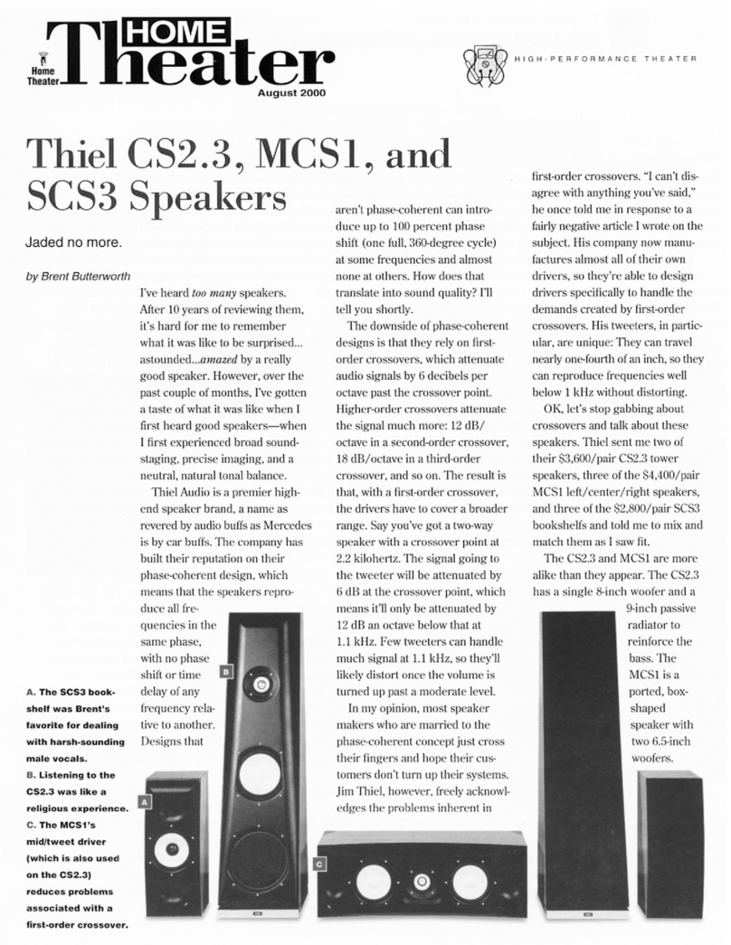
Thiel CS2.3 Dimensions
Thiel
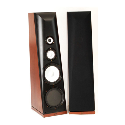
Thiel CS 7.2 Manual
Thiel
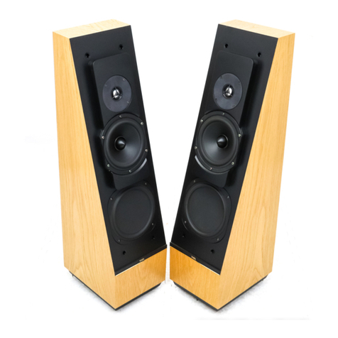
Thiel CS1.5 User manual
Thiel
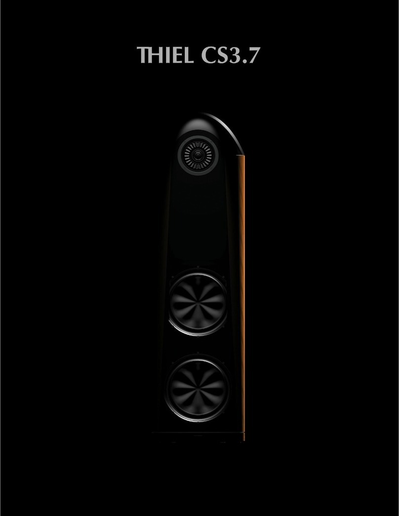
Thiel Coherent Source CS3.7 User manual
Thiel
Thiel CS2.4 User manual
Thiel
Thiel CS.5 User manual
Thiel
Thiel CS1.6 User manual

Thiel
Thiel CS1.5 Manual
Thiel
Thiel CS3.6 User manual
Thiel
Thiel CS6 Manual

Thiel
Thiel PowerPoint 1.2 User manual

Thiel
Thiel CS.5 Dimensions
Thiel
Thiel PowerPlane 1.2 User manual
Thiel
Thiel Coherent Source CS3.6 Manual
Thiel
Thiel CS2.4 User manual
Thiel
Thiel Coherent Source CS.5 Manual
