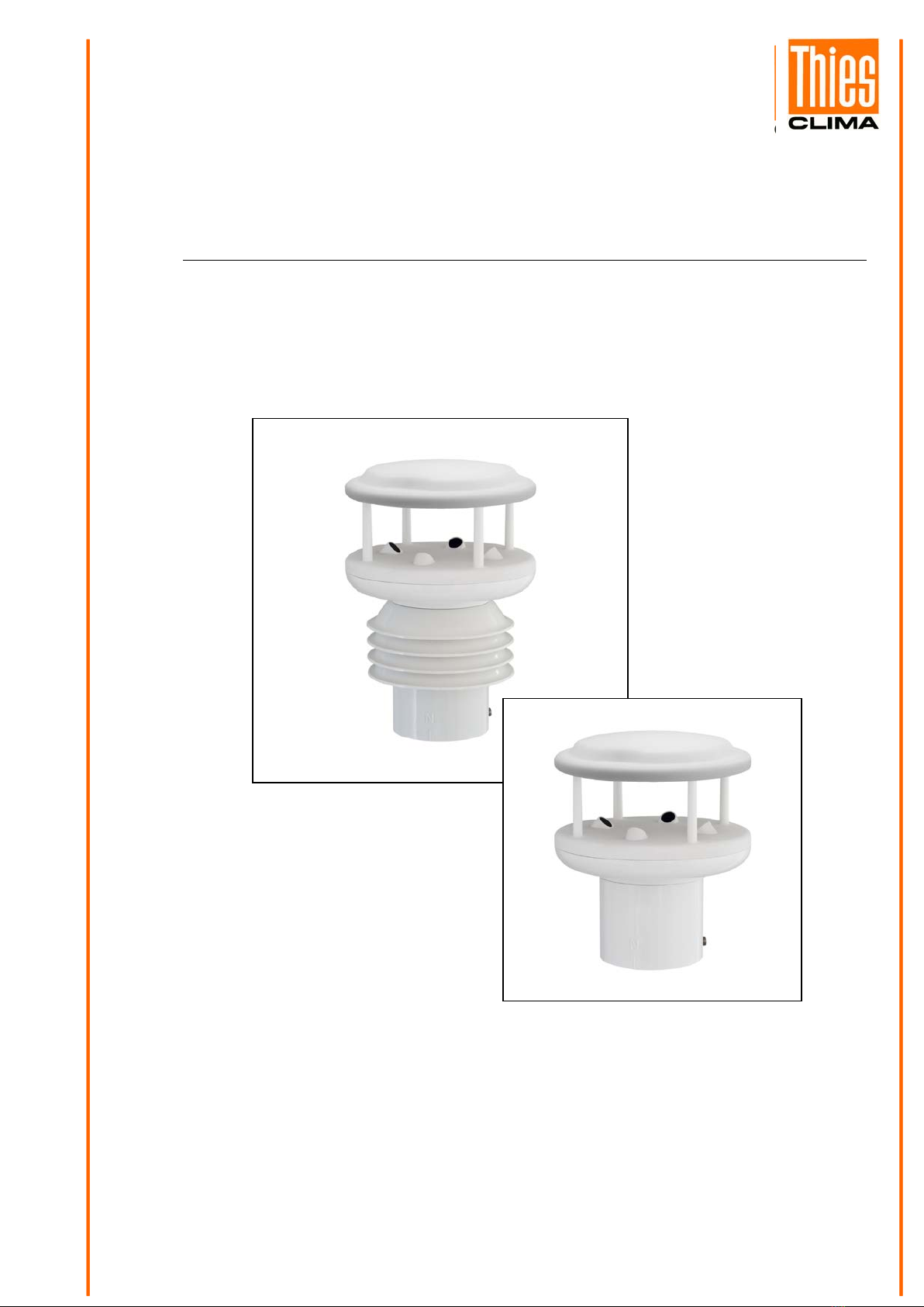
Thies CLIMA SENSOR US How to use

THE WORLD OF WEATHER DATA - THE WORLD OF WEATHER DATA - THE WORLD OF WEATHER DATA
Short manual
021690/10/14/short
CLIMA SENSOR US
4.920x.00.00x
ADOLF THIES GmbH & Co. KG
Hauptstraße 76 37083 Göttingen Germany
Box 3536 + 3541 37025 Göttingen
Phone +49 551 79001-0 Fax +49 551 79001-65
www.thiesclima.com inf[email protected]

2 - 14 021690/10/14/short
Safety Instructions
•Before operating with or at the device/product, read through the operating instructions.
This manual contains instructions which should be followed on mounting, start-up, and operation.
A non-observance might cause:
- failure of important functions
- endangerment of persons by electrical or mechanical effect
- damage to objects
•Mounting, electrical connection and wiring of the device/product must be carried out only by a qualified
technician who is familiar with and observes the engineering regulations, provisions and standards applicable in
each case.
•Repairs and maintenance may only be carried out by trained staff or Adolf Thies GmbH & Co. KG. Only
components and spare parts supplied and/or recommended by Adolf Thies GmbH & Co. KG should be used
for repairs.
•Electrical devices/products must be mounted and wired only in a voltage-free state.
•Adolf Thies GmbH & Co KG guarantees proper functioning of the device/products provided that no
modifications have been made to the mechanics, electronics or software, and that the following points are
observed:
•All information, warnings and instructions for use included in these operating instructions must be taken into
account and observed as this is essential to ensure trouble-free operation and a safe condition of the measuring
system / device / product.
•The device / product is designed for a specific application as described in these operating instructions.
•The device / product should be operated with the accessories and consumables supplied and/or recommended
by Adolf Thies GmbH & Co KG .
•Recommendation: As it is possible that each measuring system / device / product may,under certain conditions,
and in rare cases, may also output erroneous measuring values, it is recommended using redundant systems
with plausibility checks for security-relevant applications.
Environment
•As a longstanding manufacturer of sensors Adolf Thies GmbH & Co KG is committed to the
objectives of environmental protection and is therefore willing to take back all supplied
products governed by the provisions of "ElektroG" (German Electrical and Electronic
Equipment Act) and to perform environmentally compatible disposal and recycling. We are
prepared to take back all Thies products concerned free of charge if returned to Thies by our
customers carriage-paid.
•Make sure you retain packaging for storage or transport of products. Should packaging
however no longer be required, please arrange for recycling as the packaging materials are
designed to be recycled.
Documentation
•© Copyright Adolf Thies GmbH & Co KG, Göttingen / Germany
•Although these operating instruction has been drawn up with due care, Adolf Thies GmbH & Co KG can
accept no liability whatsoever for any technical and typographical errors or omissions in this document that
might remain.
•We can accept no liability whatsoever for any losses arising from the information contained in this document.
•Subject to modification in terms of content.
•The device / product should not be passed on without the/these operating instructions.
Remark:
This document is an instruction for starting-up the
ClimaSensorUS. For the complete Instructions for Use please
refer to the attached CD.

3 - 14 021690/10/14/short
1 Introduction
Thies “brief instruction” describes the installation and startup of the “ClimaSensorUS” by means of
the PC-program “ThiesDeviceUtility”.
Article- No.
Description
Parameter, output, interface, equipment, etc.
4.920x.00.00x
CLIMA SENSOR US
You will find each the complete and detailed
Instruction for Use on the attached CD.
9.1700.81.000
Program “ThiesDeviceUtility.EXE”
Scope of Delivery:
1 x ClimaSensorUS 4.920x.00.00x
1 x Brief instruction for 4.920x.00.00x
1 x Supplementary sheet with the factory settings
1 x CD with:
Program “ThiesDeviceUtility.EXE” (9.1700.81.000)
Manual “ThiesDeviceUtility”
Instruction for Use for 4.920x.00.00x
Please check the completeness of delivery.
For an initial start-up, we recommend to use a PC, the power supply unit 9.3389.20.000, the
connecting cable 509427 or 509311, and the interface converter 9.1702.40.000. For connection
diagrams for wiring please refer to chapter 3.
2 Installation of the CLIMA SENSOR US
Attention:
The working position of the CLIMA SENSOR US is vertical (plug
connection underneath).
During mounting, de-mounting, transport or maintenance of the
CLIMA SENSOR US please make sure that no water gets into
the instrument base or plug.
When using a lightning rod please take care that it is mounted
at below 45° to a wind measuring distance, in order to avoid
malfunctions caused by reflections.
The instrument must be mounted and wired only by qualified
personnel, who knows and observes the generalities of
techniques, and applicable regulations and norms.

4 - 14 021690/10/14/short
2.1 Mechanical installation
Proper installation of the CLIMA SENSOR US is carried
out using a tube socket R1½" (Ø 48.3 mm) and at least
30 mm in length. The inside diameter of the tube socket
must be at least 30 mm as the electrical connection of
the CLIMA SENSOR US is carried out at the bottom of
the device. After connection the CLIMA SENSOR US is
then mounted on the tube or mast socket. The marking
for north on the device must be aligned to north (see
section 4.2.1). The device is fixed to the shaft with the
two Allen screws (AF 4 mm).
Caution:
The allen screws must be
tightened to 2 Nm
2.1.1 Alignment to north
For exact determination of the wind and Brightness
direction the CLIMA SENSOR US must be installed
aligned to north (true north).
When aligning the device, the marking for north (N)
must point to north (true north). To do so, select a
conspicuous feature of the landscape to the north or
south with a compass and turn the mast or sensor until
the marking for north points to true north.
When aligning the device to north using a compass, bear
in mind the magnetic variation (= deviation in the
direction of the compass needle from true north) and
possible interference from magnetic fields (e.g. iron
parts, electric cables).
The lower edge of the sensor base is equipped with a
bore for north aligned to the marking for north. This
bore allows a mast adapter with a pin for north to be
used here. The mast adapter is not included in the scope
of supply.

5 - 14 021690/10/14/short
2.2 Electrical installation / Start-up
1. The connection of the ClimaSensor US to the interface module and power supply unit
differs, depending on the instrument variant. You have to distinguish between the
connection types full-duplex and half-duplex with cable 16pole or resp. 8pole. Information
on the duplex-mode are given by parameter DM on the supplemental sheet “Factory
settings” of the ClimaSensor US.
The following table serves for the circuit diagram selection. The following assignments
apply:
Cable
Parameter DM
Used duplex-mode
Connection diagram
16pole
1
Full-duplex
Chapter 3page 7
16pole
2
Full-duplex
Chapter 3page 7
8pole
0
Half-duplex
Chapter 5page 9
8pole
1
Full-duplex
Chapter 4page 8
8pole
2
Full-duplex
Chapter 4page 8
Table 1: Selection Connection Diagram
2. Connect the supplied 8pole or resp. 16pole cable to the power supply unit 9.3389.20.000,
acc. to the connection diagram, see Table 1.
3. Put the plug of the 8pole or resp. 16pole cable into the ClimaSensorUS.
4. Connect the USB/RS485 interface converter to the power supply unit 9.3389.20.000.
5. Connect the 230V / 115V line to the power supply unit
9.3389.20.000.
6. Insert the included CD into the CD-ROM drive of your
PC.
7. Start the program “ThiesDeviceUtilityStartup.exe” from
the included CD.
8. For installation of the interface transducer select the
button “install driver for USB RS485 converter”.
9. Connect the USB/RS485 interface converter and your
PC by means of the included USB-cable.
10. For starting the program “ThiesDeviceUtility.exe” select the button “Start Thies
DeviceUtility” in the program
“ThiesDeviceUtilityStartup”.
11. After the program start select the button “Search”.
12. The program searches for connected instruments,
and displays the search result and detail
parameter.

6 - 14 021690/10/14/short
13. By pressing the button “Terminal” a window is opened, where individual commands can be
sent, and parameters can be changed. See also the online help of the program “Thies
Device Utility.exe”. The program supports both the “Thies”- and the MODBUS-command
interpreter. Depending on the identified device the command interpreter is selected
automatically.
14. By operating the switch “PDF” the instructions for use of the instrument are opened in the
current line.
15. For information on mounting, installation, and other technical details please refer to the
instructions for use.

7 - 14 021690/10/14/short
3 Connection Diagram of 4.920x.00.000 in Full-duplex Mode and
16pole Connecting Cable
Ausgang skalierbar / Output scallable
Vollduplex
FullDuplex
TXD+
TXD -
RXD +
RXD -
GND
GND
0 ... 10V = 0 ... 360 ° Helligkeit / Brightness
0 ... 10V = 1 ... 120 K Lux Helligkeit / Brightness
0 ... 10V = 800 ... 1060 hPa Luftdruck / Air Pressure
0 ... 10V = 0 ... 100 % rel. Feuchte . / Humidity
0 ... 10V = - 40 ... + 60 °C Lufttemperatur / Air Temperature
0 ... 10V = 0,001 ... 100 mm / h Niederschlag / Precipitation
0 ... 10V = 0 ... 360 ° Windrichtung / Wind Direction
0 ... 10V = 0 ... 60 m/s Windgeschwindigkeit / Wind velocity
1
2
3
4
5
6
7
8
über 100m : verdrillte Leitungen verwenden
above 100m : use Twist Pair Line
RS 422 Full duplex
RS 422 Vollduplex
2 3 4
ON Dip- Schalter
Dip - Switch
1
Klemmleiste/Clamp con.
serielleSchnittstelle
serialInterface
Vollduplex/Full duplex
1,2 =ON
3,4 =OFF
9.1702.40.000
RS422 /485 /USB
LevelConverterisolation
Schnittstellenwandler
12 3 94 5 6 7 8
9pin D -Stecker/Plug
2 3 41
TXD -
TXD +
RXD +
RXD -
5 6
SG
M16x 1,5
M16x 1,5
Netz / Mains
115V 50 / 60 Hz
Schirm
Shield
oder / or
Trafo BV 11583
0 - 115 - 230 V
Sek . Sec.
Fuse 1,25 AT
rot/ red
rot/ red
schwarz / black
gelb / yellow
grau / greey
M20x 1,5
1
15
2 3 4 5 6 7 8
22212019
1817
16
9 10 11 12 13
2726
2524
23
14
28
S
S
24VAC
Fuse 1,25AT
24VAC230V
0
0
115V
115V Netz / Mains
230V 50 / 60 Hz
0230 V
blau / blue
24V AC / 30 VA
9. 3389. 20. 000
Netzgerät / Power Supply
Clima Sensor US
gelb -grün
yellow-green
19pol Stecker/ Plug
weiß - grün / white - green
weiß - white
grün - green
grau - grey
blau - blue
schwarz - black
gelb - yellow
braun - brown
Clima Sensor US ........
4. 920x. 00. 000
NC
weiß - gelb / white - yellow
braun - grün / brown - green
grau - rosa / grey - pink
rot - blau / red - blue
gelb - braun / yellow - brown
violett - violet
rosa - pink
rot - red
NC
TXD+
L
TXD -
K
RXD +
U
RXD -
M
GND
I
GND
H
10V HR°
A
10V Lux
B
10V hPa
C
10V % rF
N
10V °C
O
10V NS
P
10V WR°
S
10V m/s
T
+ 24V AC/DC
E
+ 24V AC/DC
F
- 24V AC/DC
D
- 24V AC/DC
G
- 24V R
R
Clima Sensor US NHTFB , 4. 9200. 00. 000
Clima Sensor US TFB , 4. 9201. 00. 000
Clima Sensor US NH , 4. 9202. 00. 000
Clima Sensor US , 4. 9203. 00. 000
Ausgang / Output :
Ausgang / Output :
Ausgang / Output :
Ausgang / Output :
1 , 2 , 3 , 4 , 5 , 6 , 7 , 8
1 , 2 , 3 , 4 , 5
1 , 2 , 6 , 7 , 8
1 , 2
Vollduplex / Full duplex
USB
USB
Notebook
P C
Kabel / Cable
509 311
Geräte -Konfiguration
sieheBestell-Nr.
Bedienungsanleitung
Instument-Configuration
seeOrder-No.
Instructionforuse

8 - 14 021690/10/14/short
4 Connection Diagram of 4.9200.00.000 in Full-duplex Mode and
8pole Connecting Cable
Vollduplex
Full Duplex
TXD+
TXD -
RXD +
RXD -
GND
über 100m : verdrillte Leitungen verwenden
above 100m : use Twist Pair Line
RS 422 Full duplex
RS 422 Vollduplex
234
ON Dip - Schalter
Dip - Switch
1
Klemmleiste / Clamp con.
serielle Schnittstelle
serial Interface
Vollduplex / Full duplex
1 , 2 = ON
3 , 4 = OFF
9. 1702. 40. 000
RS 422 / 485 / USB
Level Converter isolation
Schnittstellenwandler
12 3 94 5 6 7 8
9 pin D - Stecker / Plug
2 3 41
TXD -
TXD +
RXD +
RXD -
5 6
SG
M16 x 1,5
M16 x 1,5
Netz / Mains
115V50 /60Hz
Schirm
Shield
oder / or
Trafo BV 11583
0 - 115 - 230 V
Sek . Sec.
Fuse 1,25 AT
rot/ red
rot/ red
schwarz / black
gelb / yellow
grau / greey
M20 x 1,5
1
15
2 3 4 5 6 7 8
2221
20
19181716
9 10 11 12 13
27
26252423
14
28
S
S
24VAC
Fuse1,25AT
24VAC
230V
0
0
115V
115V Netz / Mains
230V50 /60Hz
0230V
blau/blue
24V AC / 30 VA 9. 3389. 20. 000
Netzgerät / Power Supply
Clima Sensor US
gelb - grün
yellow- green
19 pol Stecker / Plug
weiß - white
grün - green
grau - grey
blau - blue
gelb - yellow
braun - brown
Clima Sensor US ........
4.920x.00.000
NC
rot - red
NC
TXD+
L
TXD -
K
RXD +
U
RXD -
M
GND
I HABCNOPST
+ 24V AC/DC
E
+ 24V AC/DC
F
- 24V AC/DC
D
- 24V AC/DC
G
-24V R
R
Clima Sensor US NHTFB
Clima Sensor USTFB
Clima Sensor USNH
Clima Sensor US
4. 9200. 00. 000
4. 9201. 00. 000
4. 9202. 00. 000
4. 9203. 00. 000
Vollduplex /Full duplex
USB
USB
Notebook
P C
NC
Kabel/Cable
509427
no connecting
Nichtbelegt
Geräte - Konfiguration
siehe Bestell - Nr.
Bedienungsanleitung
Instument - Configuration
see Order - No.
Instruction for use

9 - 14 021690/10/14/short
5 Connection Cable of 4.920x.00.000 / 001 in Half-duplex Mode and
8pole Connection Cable
Halbduplex
Half Duplex
TXD+ /RXD+
TXD -/ RXD -
GND
über 100m: verdrillteLeitungenverwenden
above 100m:use TwistPair Line
RS 422 Half duplex
RS 422 Halbduplex
Dip - Schalter
Dip - Switch
Klemmleiste / Clamp con.
serielle Schnittstelle
serial Interface
Halbduplex / Halfduplex
1 , 2 = OFF
3 , 4 = ON
9. 1702. 40. 000
RS422 / 485 / USB
Level Converter isolation
Schnittstellenwandler
12 3 94 5 6 7 8
9 pin D - Stecker / Plug
2 3 41
TXD -
TXD +
RXD+
RXD-
5 6
SG
M16 x1,5
M16 x1,5
Netz / Mains
115V 50 / 60 Hz
Schirm
Shield
oder / or
TrafoBV11583
0 - 115- 230 V
Sek . Sec.
Fuse1,25AT
rot/ red
rot/ red
schwarz / black
gelb / yellow
grau / greey
M20 x1,5
1
15
2 3 4 5 6 7 8
22212019
1817
16
9 10 11 12 13
2726
2524
23
14
28
S
S
24VAC
Fuse1,25AT
24VAC
230V
0
0
115V
115V Netz / Mains
230V 50 / 60 Hz
0230 V
blau/blue
24VAC/30 VA 9.3389.20.000
Netzgerät/ Power Supply
ClimaSensor US
gelb - grün
yellow - green
19 pol Stecker / Plug
weiß - white
grün - green
grau - grey
blau - blue
gelb - yellow
braun - brown
Clima Sensor US ........
4. 920x. 00. 000
NC
rot - red
NC
TXD+/ RXD+
L
TXD - / RXD -
KUMI HABCNOPST
+ 24V AC/DC
E
+ 24V AC/DC
F
- 24V AC/DC
D
- 24V AC/DC
G
- 24V R
R
Clima Sensor US NHTFB
Clima Sensor US TFB
Clima Sensor US NH
Clima Sensor US
4. 9200. 00. 000
4. 9201. 00. 000
4. 9202. 00. 000
4. 9203. 00. 000
NC
NC
Halbduplex / Half duplex
Kabel / Cable
509 427
USB
USB
Notebook
PC
2 3 4
ON
1
no connecting
Nichtbelegt
Geräte - Konfiguration
siehe Bestell - Nr.
Bedienungsanleitung
Instument - Configuration
see Order - No.
Instruction for use

10 - 14 021690/10/14/short
6 Installation of the USB/RS485 Interface Converter 9.1702.40.000
For the installation of the USB/RS485 interface converter please proceed as follows:
1. Insert the included CD into the CD-ROM drive.
2. Put the USB-plug of the RS485 converter into the provided socket of the PC.
3. The PC identifies a new instrument, and displays it as follows:
4. Select in the dialogue “No, not this time”.
5. Acknowledge the next dialogue with OK.
6. Windows will install the driver for the USB/RS485 converter.
7. After successful completion the instrument is ready for use.
8. In the Windows system control a new COM-port is registered. The program
“ThiesDeviceUtility.EXE” is using this port automatically.
9. Settings for RS485 half-duplex operation.
In half-duplex operation the connections 1,2, and 5 are used. The sliding switches have to
be set as follows:
1: OFF 3: ON
2: OFF 4: ON
10. Settings for RS485 full-duplex operation.
In full-duplex operation the connections 1,2,3,4, and 5 are used. The sliding switches must
be set as follows:
1: ON 3: OFF
2: ON 4: OFF

11 - 14 021690/10/14/short
7 Dimensional Drawing
Nord-Bohrung /
North-drilling
Steckverbindung /
Connector

12 - 14 021690/10/14/short
8 Technical Data
Wind speed Measuring range 0.01 m/s...60 m/s
Scaling of analogue output freely selectable
Accuracy ≤ 5 m/s:
±0.3 m/s (rms - mean over 360°)
5...60m/s:
±3 % of measured value (rms - mean over
360°)
Resolution 0.1 m/s:
in telegrams 1, 2, 3, 5, 6
0.01 m/s:
in telegram 14
Wind direction
Measuring range 0...360°
Accuracy ±2.0° with WS > 2 m/s
Resolution 1°:
in telegrams 1, 2, 3, 4, 6
0.1°:
in telegrams 5, 14
Virtual temperature
Measuring range -40°C ...+80°C
Accuracy ±0.5 K
Resolution 0.1 K
Air temperature Measuring range -40°C …+80°C
Accuracy ±0.3 K @ 25°C, ±1.0 K above -40°C …+80°C
Resolution 0.1 K
Long-term stability < 0.04 K per year
Air humidity, relative Measuring range 0% …100% relative humidity
Accuracy ±1.8% of 10% …90%, ±3.0% of 0% …100%
Long-term stability < 0.5% per year
Resolution 0.1%
Air pressure Measuring range 300 hPa …1100 hPa
Accuracy ±0.25 hPa at +10…+35°C
±1 hPa at -20…+60°C
Resolution 0.1 hPa
Long-term stability < ±1 hPa per year
Brightness
Measuring range 1 lux …150 klux
Accuracy 0,3% of relative measured value
Resolution approx. 0,3% of measuring value
Precipitation Measuring ranges:
Intensities 0.001 mm/h … 999 mm/h
Resolution intensity 0.001 mm/h
Daily total 0.01 mm … 999 mm
Resolution daily total 0.01 mm
Droplet size 0.25 mm to 5.0mm, large as hail
Accuracy with
precipitation with 95% of the precipitations deviations less than 15%
compared with Thies Laser Precipitation Monitor (Reference)
Type of precipitation Rain, snow, sleet, ice crystals, hail
Data output digital Interface RS 485 / RS 422
Electrically isolated from supply
Baud rate 1200, 2400, 4800, 9600, 19200, 38400, 57600, 115200,
230400, 460800, 921600 selectable
Output Instantaneous values, sliding means from 100 msec

13 - 14 021690/10/14/short
to 2 min in increments of 100 msec freely selectable
Output rate One per 10 msec to one per 60 seconds in increments of 1
msec freely selectable
Protocol ASCII- Thies-Format and MODBUS RTU
Data output analogue
Electrical outputs 0... 10 V
Electrically isolated from supply
Permissible burden on voltage output: ≥ 2000Ω
Output
Instantaneous values, sliding means from 100 msec to 2 min
in increments of 100 msec freely selectable
Output rate Update rate 10 msec
Resolution 16 bit
General Internal measuring
rate Wind: up to 1000 propagation time measurements per
second, up to 250 complete measuring sequences/second
incl. calculations
Temperature, humidity, pressure, precipitation, brightness:
updated 1x a second
Bus mode Bus mode with up to 99 devices possible
Firmware update Firmware update in full duplex mode via RS422
Temperature range Operating temperature -30 ... +70°C
Storage temperature -55 ... +80°C
Operating voltage Supply without cover
heating 6V...40 V DC or 10...28 V AC 50Hz / 60Hz
typ. 50 mA @ 24V
Operating voltage Supply with cover
heating 24 V AC/DC ±15%, 25 VA typically @ 24 V nominal
(execution only 4.9200.00.00x, 4.9202.00.00x)
Type of protection IP 67 (when mounted correctly, see section "Preparation for
operation")
Housing 4.92xx.xx.xxx Plastic: LEXAN (polycarbonate, UV-stabilised) impact and
weather-resistant
Mounting e.g. on mast tube R1½" (Ø 48.3 mm)
Type of connection 19-pin plug connection
Weight approx. 900g (full version)

14 - 14 021690/10/14/short
ADOLF THIES GmbH & Co. KG
Hauptstraße 76 37083 Göttingen Germany
P.O. Box 3536 + 3541 37025 Göttingen
Phone +49 551 79001-0 Fax +49 551 79001-65
- Alterations reserved -
Other manuals for SENSOR US
1
Table of contents
Other Thies CLIMA Accessories manuals
Popular Accessories manuals by other brands

Beurer
Beurer UB30 Instructions for use

MOPEKA
MOPEKA Standard Sensor Installation manual operating instructions

Chad Valley
Chad Valley Giant Wavy Slide Assembly & user instructions

Energy Intelligence
Energy Intelligence LTU ULTRA LITE instruction manual

Philips
Philips DLA81002H brochure

Stobag
Stobag SKIROSOL SRCK 601 Instructions and warnings for the fitter