Thies CLIMA 7.1419.21 81 Series User manual

Silicon Irradiance Sensor
Instruction for Use
7.1419.21.x81
7.1419.20.x81
Dok. No. 022040/02/23
T H E W O R L D O F W E A T H E R D A T A
© Adolf Thies GmbH & Co. KG · Hauptstraße 76 · 37083 Göttingen · Germany 022040/02/23
Tel. +49 551 79001-0 · Fax +49 551 79001-65 · inf[email protected] · www.thiesclima.com Seite 2 von 14
Safety Instructions
•Before operating with or at the device/product, read through the operating instructions.
This manual contains instructions which should be followed on mounting, start-up, and operation.
A non-observance might cause:
- failure of important functions
- endangerment of persons by electrical or mechanical effect
- damage to objects
•Mounting
, electrical connection and wiring of the device/product must be carried out only by a qualified
technician who is familiar with and observes the engineering regulations, provisions and standards ap-
plicable in each case.
•Repairs and maintenance may only be carried out by trained staff or Adolf Thies GmbH & Co. KG.
Only components and spare parts supplied and/or recommended by Adolf Thies GmbH & Co. KG
should be used for repairs.
•Electrical devices/products must be mounted and wired only in a voltage-free state.
•Adolf Thies GmbH & Co KG guarantees proper functioning of the device/products provided that no
modifications have been made to the mechanics, electronics or software, and that the following points
are observed:
•All information, warnings and instructions for use included in these operating instructions must be
taken into account and observed as this is essential to ensure trouble-free operation and a safe condi-
tion of the measuring system / device / product.
•The device / product is designed for a specific application as described in these operating instructions.
•The device / product should be operated with the accessories and consumables supplied and/or rec-
ommended by Adolf Thies GmbH & Co KG .
•Recommendation: As it is possible that each measuring system / device / product may, under certain
conditions, and in rare cases, may also output erroneous measuring values, it is recommended using
redundant systems with plausibility checks for security-relevant applications.
Environment
•As a longstanding manufacturer of sensors Adolf Thies GmbH & Co KG is committed
to the objectives of environmental protection and is therefore willing to take back all
supplied products governed by the provisions of "ElektroG" (German Electrical and
Electronic Equipment Act) and to perform environmentally compatible disposal and
recycling. We are prepared to take back all Thies products concerned free of charge if
returned to Thies by our customers carriage-paid.
•Make sure you retain packaging for storage or transport of products. Should packag-
ing however no longer be required, please arrange for recycling as the packaging ma-
terials are designed to be recycled.
Documentation
•© Copyright Adolf Thies GmbH & Co KG, Göttingen / Germany
•Although these operating instructions have been drawn up with due care, Adolf Thies GmbH & Co
KG can accept no liability whatsoever for any technical and Typeographical errors or omissions in this
document that might remain.
•We can accept no liability whatsoever for any losses arising from the information contained in this doc-
ument.
•Subject to modification in terms of content.
•The device / product should not be passed on without the/these operating instructions.

© Adolf Thies GmbH & Co. KG · Hauptstraße 76 · 37083 Göttingen · Germany 022040/02/23
Tel. +49 551 79001-0 · Fax +49 551 79001-65 · inf[email protected] · www.thiesclima.com Seite 3 von 14
Table of contents
1Models............................................................................................................................ 4
2Application...................................................................................................................... 4
3Setup and Mode of Operation......................................................................................... 4
3.1 Mechanical design.....................................................................................................5
3.2 Optional temperature measurement ..........................................................................5
4Recommendation Side Selection / Standard Installation................................................. 5
5Installation....................................................................................................................... 5
5.1 Mechanical Mounting.................................................................................................5
5.2 Electrical Connection.................................................................................................6
5.2.1 Cable ................................................................................................................. 6
5.2.2 Connection recommendation for the cable shield............................................... 6
5.2.3 Plug and Cable Mounting................................................................................... 6
5.3 Connection Diagram..................................................................................................7
6Maintenance................................................................................................................... 7
7Interface.......................................................................................................................... 7
7.1 Supported Settings....................................................................................................8
7.2 Modbus Specification ................................................................................................8
8Technical Data...............................................................................................................12
9Dimensional Drawing.....................................................................................................12
10 EC-Declaration of Conformity .....................................................................................13
11 More Information / Documents as download...............................................................14
© Adolf Thies GmbH & Co. KG · Hauptstraße 76 · 37083 Göttingen · Germany 022040/02/23
Tel. +49 551 79001-0 · Fax +49 551 79001-65 · inf[email protected] · www.thiesclima.com Seite 4 von 14
1 Models
Scope of supply:
1 x Silicon Irradiance Sensor
1 x Instruction for Use
1 x Cable socket (mating connector) is included in the scope of delivery, if no cable is sold.
The instructions for use are available for download under the following link:
https://www.thiesclima.com/db/dnl/7.1419.2x.xxx_Silicon_Irradiance_Sensor_en.pdf
2 Application
Silicon irradiance sensors (Si sensor) show a but rugged and reliable solution for the meas-
urement of solar irradiance, especially for the monitoring of Photovoltaic (PV) systems. Based
on the construction of the sensor element corresponding to a PV module they are ideal as
reference for the monitoring of PV systems. Especially the spectral response comparable to
PV modules as well as the similar inclination error (incident angle modifier) allow an exact
analysis of PV energy yields using Si sensor data.
3 Setup and Mode of Operation
A silicon solar cell can be used as an irradiance sensor, because the short-circuit current is
proportional to the irradiance. Our sensors are built out of a monocrystalline Si solar cell con-
nected to a shunt. Due to the low resistance of the shunt the cell operates next to short-circuit.
To minimize influences of temperature to the measuring signal all of our sensors
have an active temperature compensation via a temperature sensor laminated to the back
surface of the solar cell.
All sensors are calibrated in artificial sunlight against a reference cell calibrated
at the Physikalisch-Technische Bundesanstalt (PTB, National Metrology Institute of
Germany).
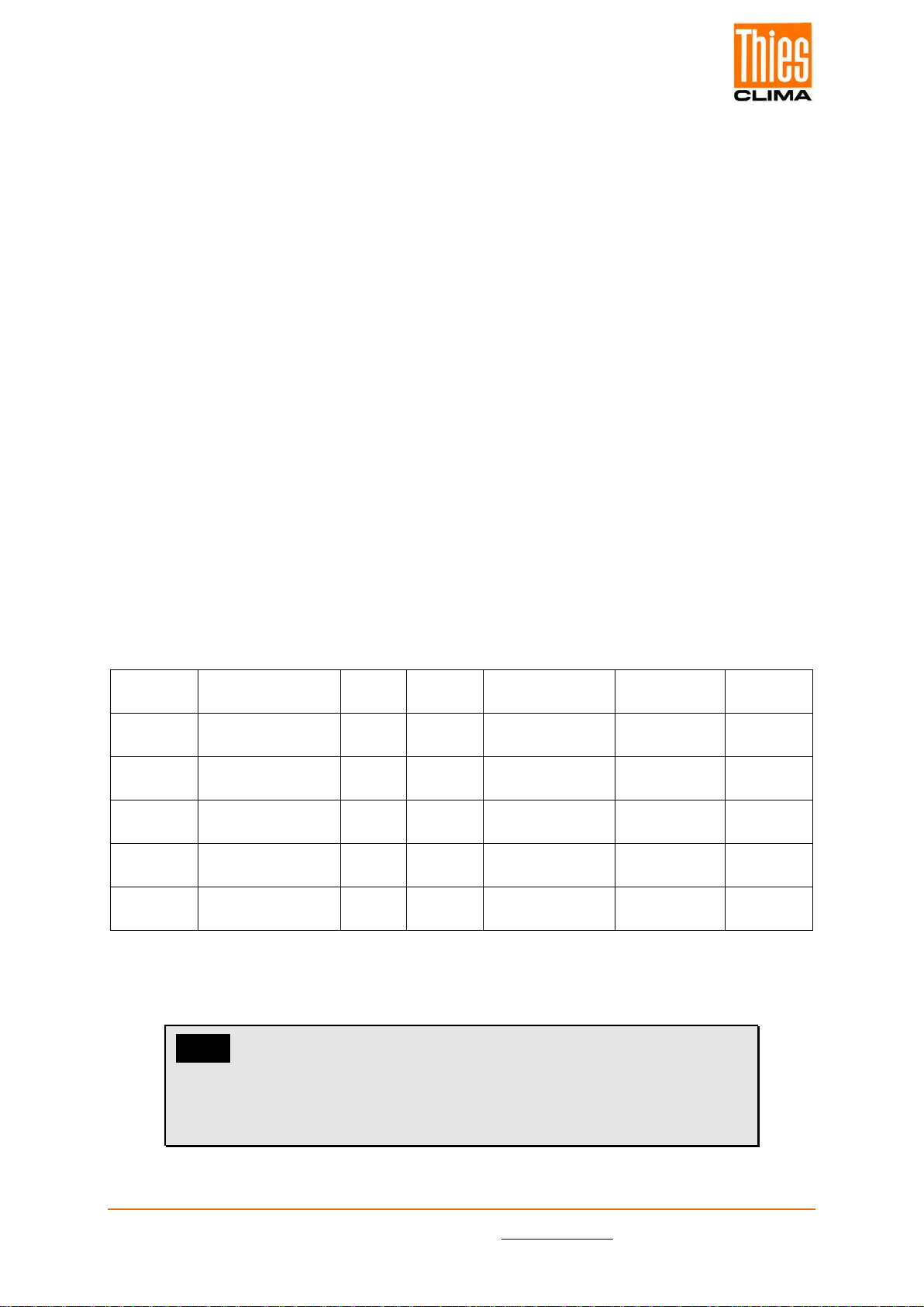
Article No.
Description
Interface /
Data output
Supply
Connection
type
7.1419.20.081
Solar irradiance incl. cell tem-
perature sensor
RS 485 /
Modbus RTU
10 … 28V DC
3m calbe
7.1419.20.781
Solar irradiance incl. cell tem-
perature sensor
RS 485 /
Modbus RTU
10 … 28V DC
Plug
7.1419.21.081
Solar irradiance incl. cell tem-
perature and
module temperature sensor
RS 485 /
Modbus RTU
10 … 28V DC
3m cable
7.1419.21.781
Solar irradiance incl. cell tem-
perature and
module temperature sensor
RS 485 /
Modbus RTU
10 … 28V DC
Plug
© Adolf Thies GmbH & Co. KG · Hauptstraße 76 · 37083 Göttingen · Germany 022040/02/23
Tel. +49 551 79001-0 · Fax +49 551 79001-65 · inf[email protected] · www.thiesclima.com Seite 5 von 14
3.1 Mechanical design
The solar cell is embedded in Ethylen-Vinyl-Acetat (EVA) between glass and Tedlar. The lam-
inated cell is integrated into a case of powder-coated aluminium. Therefore the sensor con-
struction is comparable to that of a standard PV module. The electrical connection is realized
by a 3m cable or a water proof (IP67) connector.
3.2 Optional temperature measurement
Additionally to the irradiance measurement our silicon sensors are able to measure the tem-
perature of the solar cell using a temperature sensor laminated to the back of the cell. This
solar cell temperature can approximately be used as module temperature.
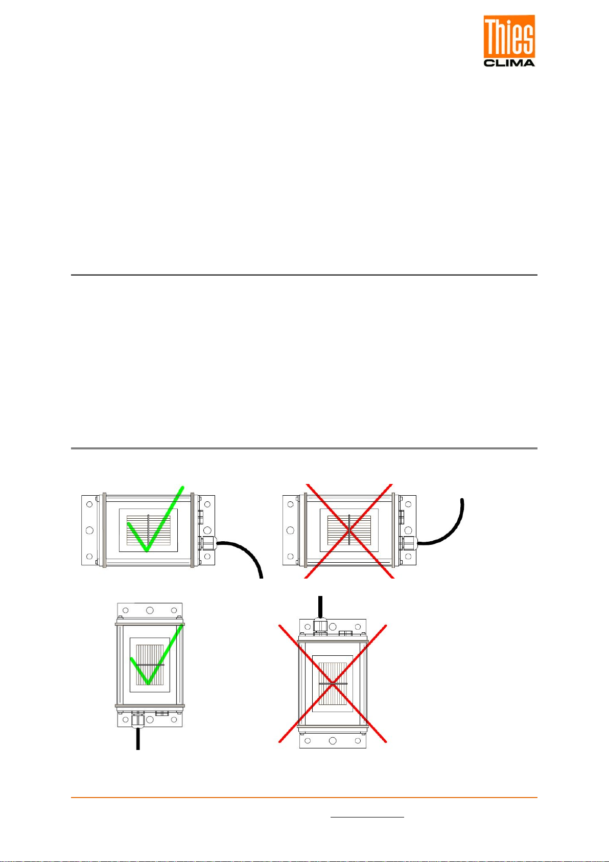
4 Recommendation Side Selection / Standard Installation
Si sensors that are used for monitoring PV installations must be installed with the same align-
ment and inclination as the PV generator. The mounting location should be free of shading as
far as possible. To facilitate maintenance and cleaning of the Si sensor, the Si sensor should
be mounted in an easily accessible place.
The mounting location at a PV generator must be selected such that snow cannot jeopardise
the Si sensor as it slides off. For this reason do not mount along the drip edge on the PV
generator.
5 Installation
5.1 Mechanical Mounting

© Adolf Thies GmbH & Co. KG · Hauptstraße 76 · 37083 Göttingen · Germany 022040/02/23
Tel. +49 551 79001-0 · Fax +49 551 79001-65 · inf[email protected] · www.thiesclima.com Seite 6 von 14
5.2 Electrical Connection
The sensors are designed for safety extra-low voltage (SELV) operation. The maximum power
of the voltage supply is 50 VA.
Reversing the polarity or mixing up the connections on the Si sensor may cause irreversible
damage to the sensor. The cable shield is to be connected to PE during installation.
5.2.1 Cable
Core count / Cross-section / Type
Cable 4 x 0,25mm² LIYCY - BLACK, UV-resistant
5.2.2 Connection recommendation for the cable shield
The connecting cable should always be laid separated from, e.g. main DC cables or AC cables.
The connecting cable is to be laid so it is fixed. The minimum bending radius of 15 x cable
diameter (ø approx. 5mm) is to be observed. The voltage drop at the cable has to be consid-
ered when calculating the maximum cable length.
The pressure equalisation element must not be damaged. The cable gland is not allowed to
be undone or tightened by the user. The housing for the Si sensors is not allowed to be opened,
because as a consequence, the housing will no longer be sealed after it is closed. If the hous-
ing is nevertheless opened, no liability for the sealing can be accepted.
The surge protection concept must be adapted to the specific local situation. This means, for
instance, that the measuring cables must be equipped with a separate surge arrester at the
entry to a building. The sensor must be integrated into the lightning protection concept.
5.2.3 Plug and Cable Mounting
Coupling socket, Type: Binder, Serie 712 – 4 pol
© Adolf Thies GmbH & Co. KG · Hauptstraße 76 · 37083 Göttingen · Germany 022040/02/23
Tel. +49 551 79001-0 · Fax +49 551 79001-65 · inf[email protected] · www.thiesclima.com Seite 7 von 14
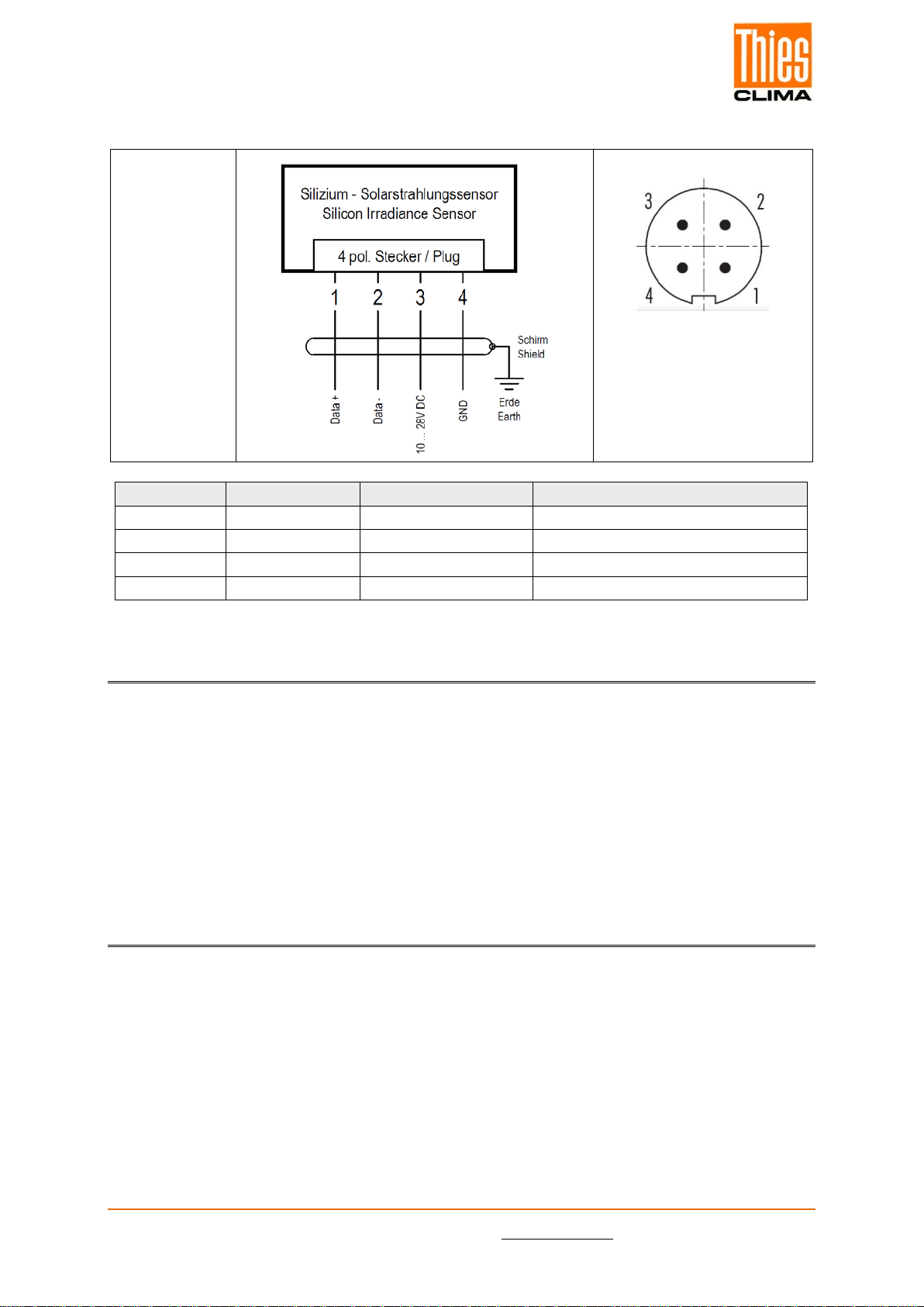
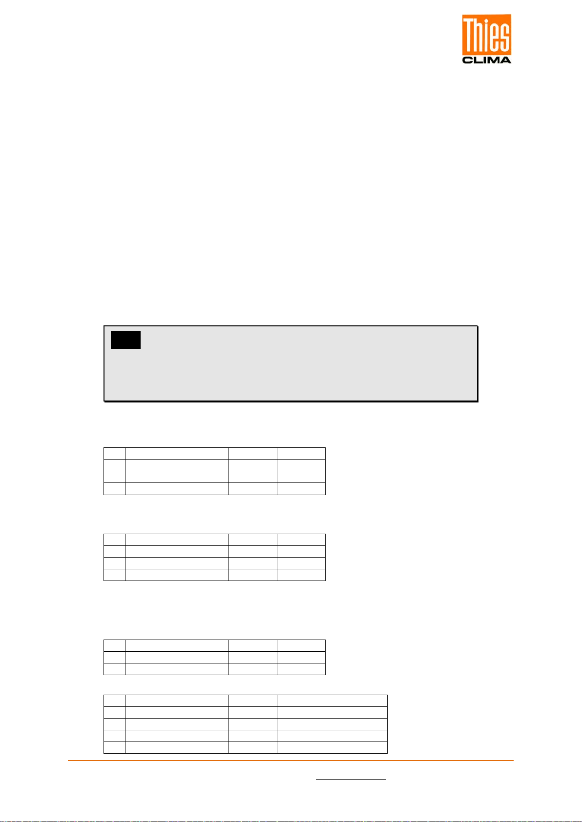
5.3 Connection Diagram
Order no.
7.1419.20.081
7.1419.20.781
7.1419.21.081
7.1419.21.781
PIN
Wire color
Name
Function
1
White
Data+
RS485 Data +
2
Brown
Data-
RS485 Data -
3
Green
VCC
Power supply +10 ... 28V DC
4
Yellow
GND
Ground
6 Maintenance
Scope of the regularly check (at least every 2 years): Cleaning of solar cell, external damage,
mechanical fastening, cable laying and any damage to the cable.
In the report IEA-PVPS T13-03: 2014 "Analytical Monitoring of Grid-connected Photovoltaic
Systems" an interval of 1 to 2 weeks is recommended.
Should damage be found that degrades the function or safety, the sensor is to be replaced.
A recalibration is recommended at least every 3 years.
7 Interface
The interface consists of an RS485 connection with the following settings:
•9600 Baud (the Baud rate can be set).
•8 Data bits.
•No parity.
•1 Stop bit.
•Data in binary format (command interpreter: MODBUS RTU).
© Adolf Thies GmbH & Co. KG · Hauptstraße 76 · 37083 Göttingen · Germany 022040/02/23
Tel. +49 551 79001-0 · Fax +49 551 79001-65 · inf[email protected] · www.thiesclima.com Seite 8 von 14
7.1 Supported Settings
Baud Rate: 1200, 2400, 9600, 19200, 38400, 57600)
Parity: None, Even, Odd
Stop Bit: 1, 2 (only at no parity)
Factory Default: 9600 Baud, 8N1, address: 1
The sensor offers the function code 0x46 of the Modbus protocol for setting the bus protocol
parameters. Should you need any further information, please do not hesitate to contact us..
7.2 Modbus Specification
References:
- Modbus over Serial Line Specification and Implementation Guide V1.02
- Modbus Application Protocol Specifiation V1.1b
Transfer mode:
- Modbus RTU.
Die Sensoren starten den Modbus-Betrieb 4 Sekunden nach dem Einschalten.
Supported short codes:
- 0x03: Read holding register
- 0x04: Read input register
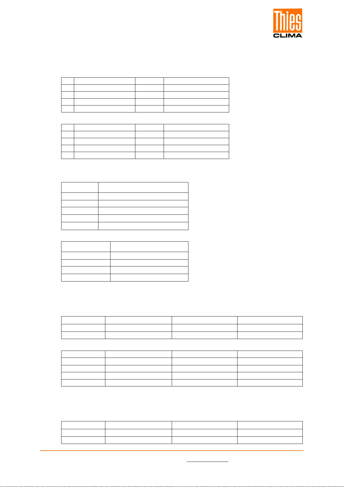
Register
Value
Gain
Offset
Phys. Range
Data Range
Data
Type
0000
Cell Temperature
in W/m²
0,1
0
0…1500W/m² 1
0…1500 1
UINT16
0003
Wind Speed in
m/s
0,1
0
0…80m/s
0…800
UINT16
00072Cell Temperature
in °C 0,1 0 -40…+90 °C -400…+900 INT16
00082External Temper-
ature no. 1 in °C 0,1 0 -40…+90 °C -400…+900 INT16
0009
3
External Temper-
ature no. 2 in °C
0,1
0
-40…+90 °C
-400…+900
INT16
1) Up to Firmware Version 1.52 is range 0…1400 W/m²
2)Only available from Firmware Version 1.53
3)Only available from Firmware Version 2.01
Note:
The Register 0003, 0008 and 0009 are optional for some sensor
types. If your sensor does not support this register, it will return
the value 0 for this register
© Adolf Thies GmbH & Co. KG · Hauptstraße 76 · 37083 Göttingen · Germany 022040/02/23
Tel. +49 551 79001-0 · Fax +49 551 79001-65 · inf[email protected] · www.thiesclima.com Seite 9 von 14
0x08: Diagnostics
Sub function 0x00: Return Query Data
Sub function 0x01: Restart Communications Option
Sub function 0x04: Force Listen Only Mode
Sub function 0x0A: Clear Counters
Sub function 0x0B: Return Bus Message Count
Sub function 0x0C: Return Bus Communication Error Count - Sub function 0x0D: Re-
turn Slave Exception Error Count
Sub function 0x0E: Return Slave Message Count
Sub function 0x0F: Return Slave No Response Count
Sub function 0x10: Return Slave NAK Count
Sub function 0x11: Return Slave Busy Count
Sub function 0x12: Return Bus Character Overrun Count
0x46: Communication Parameter
Info:
These settings will take effect after restart of the sensor by
power on reset or restart communication command (function
0x08, Sub function 01).
Sub function 04: Write Module Address
Request:
00
Address
1 Byte
1 to 247
01
Function Code
1 Byte
0X46
02
Sub Function Code
1 Byte
0x04
03
New Address
1 Byte
1 to 247
Response:
00
Address
1 Byte
1 to 247
01
Function Code
1 Byte
0X46
02
Sub Function Code
1 Byte
0x04
03
New Address
1 Byte
1 to 247
- Sub function 05: Read Communication Parameter
Request:
00
Address
1 Byte
1 to 247
01
Function Code
1 Byte
0X46
02
Sub Function Code
1 Byte
0x05
Response:
00
Address
1 Byte
1 to 247
01
Function Code
1 Byte
0X46
02
Sub Function Code
1 Byte
0x05
03
Baud rate
1 Byte
0 to 4, see table below
04
Parity / Stop Bit
1 Byte
0 to 3, see table below
© Adolf Thies GmbH & Co. KG · Hauptstraße 76 · 37083 Göttingen · Germany 022040/02/23
Tel. +49 551 79001-0 · Fax +49 551 79001-65 · inf[email protected] · www.thiesclima.com Seite 10 von 14
- Sub function 06: Write Communication Parameter
Request:
00
Address
1 Byte
1 to 247
01
Function Code
1 Byte
0X46
02
Sub Function Code
1 Byte
0x05
03
Baud rate
1 Byte
0 to 4, see table below
04
Parity / Stop Bit
1 Byte
0 to 3, see table below
Response:
00
Address
1 Byte
1 to 247
01
Function Code
1 Byte
0X46
02
Sub Function Code
1 Byte
0x05
03
Baud rate
1 Byte
0 to 4, see table below
04
Parity / Stop Bit
1 Byte
0 to 3, see table below
Communication Parameter Setting Sub Function 05 and 06
Baud Rate
Value
1200
0
2400
1
9600
2
19200
3
38400
4
Parity / Stop Bit
Value
8N1 (10 Bit)
0
8N2 (11 Bit)
1
8E1 (11 Bit)
2
8O1 (11 Bit)
3
Sub function 07: Hardware and Firmware Version
Request:
00
Address
1 Byte
1 to 247
01
Function Code
1 Byte
0x46
02
Sub Function Code
1 Byte
0x07
Response:
00
Address
1 Byte
1 to 247
01
Function Code
1 Byte
0x46
02
Sub Function Code
1 Byte
0x07
03
Hardware Version
2 Byte
0 to 65535
04
Firmware Version
2 Byte
0 to 65535
Sub function 08: Read Serial Number (from Firmware Version 1.54)
Request:
00
Address
1 Byte
1 to 247
01
Function Code
1 Byte
0x46
02
Sub Function Code
1 Byte
0x08
© Adolf Thies GmbH & Co. KG · Hauptstraße 76 · 37083 Göttingen · Germany 022040/02/23
Tel. +49 551 79001-0 · Fax +49 551 79001-65 · inf[email protected] · www.thiesclima.com Seite 11 von 14
Response:
00
Address
1 Byte
1 to 247
01
Function Code
1 Byte
0x46
02
Sub Function Code
1 Byte
0x08
031
Serial Number
30 Byte
Char
1) In firmware versions 1.54 and 1.55, the length of the serial number is fixed at 20 bytes. If
the serial number is shorter than 20 characters, the output is padded with "blank" (0x20).
The response for the "Read serial number" function consists of 30 characters and is structured
as follows:
- Any "-" characters printed on the sensor label will be omitted.
- For serial numbers less than 30 characters, the output is padded with null bytes "\0" (0x00).
Example:
Serial number printed on the sensor label:
485-12003-17-20311234
Output of Read Serial Number Function:
485120031720311234\0\0\0\0\0\0\0\0\0\0\0\0
Output of Read Serial Number Function in hex:
3438 3531 3230 3033 3137 3230 3331 3132 3334 0000 0000 0000 0000 0000 0000
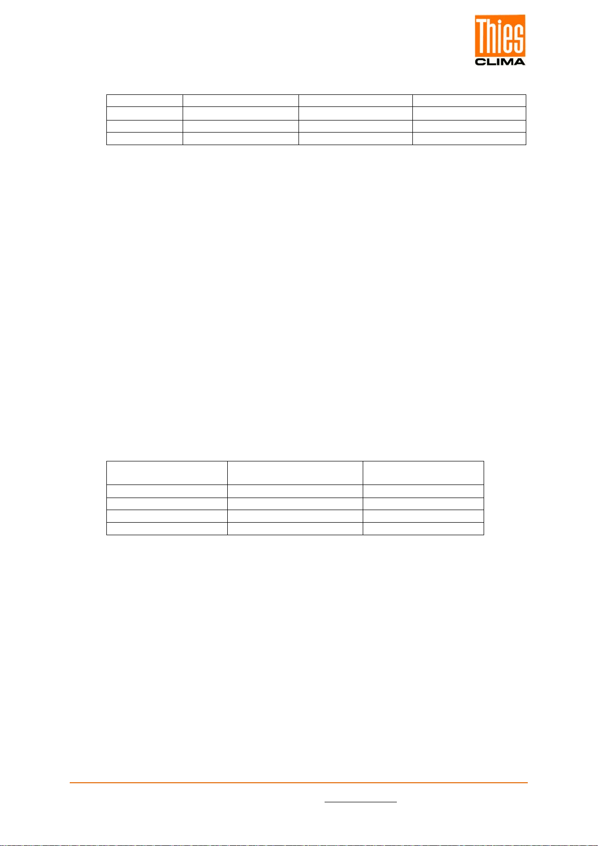
Identification of the sensor type based on the serial number:
Serial number beginning
with
Sensor Type
Active Register
485-1
Si-RS485TC-T-MB
0000, 0007
485-2
Si-RS485TC-2T-MB
0000, 0007, 0008
485-3
Si-RS485TC-2T-v-MB
0000, 0003, 0007, 0008
485-4
Si-RS485TC-T-Tm-MB
0000, 0007, 0008
Code exceptions:
- 01: Illegal Function
- 02: Illegal Data Access
- 03: Illegal Data Value
- 04: Slave Device Failure

© Adolf Thies GmbH & Co. KG · Hauptstraße 76 · 37083 Göttingen · Germany 022040/02/23
Tel. +49 551 79001-0 · Fax +49 551 79001-65 · inf[email protected] · www.thiesclima.com Seite 12 von 14
8 Technical Data
Characteristic
Description
Solar cell
Monocrystalline silicon; 50mm x 33mm
Measuring range irradiance
0 … 1500W/m²
Measurement uncertainty
1
irradi-
ance
±1W/m² ± 2,0 % v. MW
Range 100 to 1,500W/m², perpendicular incidence of light,
Spectrum AM1.5
Measuring range temperature
-40 … +90 °C
Measurement uncertainty
1
tem-
perature
1,0K in range -35 … 80°C
Ambient conditions
-35 ... +80 °C
0 ... 100% rel. Humidity, including condensation
Operating voltage
24VDC (10 ... 28VDC)
Power consumption
Typ. 25mA @ 24VDC
Connection type
4-pin connector for shielded cable
(see connection diagram)
Sensor cable
Cable 4 x 0,25mm² LIYCY, Black, UV- resistant
Max. cable length
1.000m
Galvanic isolation
Up to 1.000V between supply and RS485
Dimensions
Acc. dimensional drawing.
Weight
ca. 350 up to 470g
Type of protection
IP 65
Material
Housing
Powder-coated aluminum
1) according GUM (Guide to the Expression of Uncertainty in Measurement), k = 2
9 Dimensional Drawing

© Adolf Thies GmbH & Co. KG · Hauptstraße 76 · 37083 Göttingen · Germany 022040/02/23
Tel. +49 551 79001-0 · Fax +49 551 79001-65 · inf[email protected] · www.thiesclima.com Seite 13 von 14
10 EC-Declaration of Conformity
Manufacturer: Adolf Thies GmbH & Co. KG
Hauptstraße 76
37083 Göttingen, Germany
http://www.thiesclima.com
Product: Solar irradiance incl. cell tem-perature sensor
Doc. Nr. 2018-44970_CE
Article Overview:
7.1419.20.081 7.1419.20.781 7.1419.21.081 7.1419.21.781
2014/30/EU 26.02.2014
2017/2102/EU 15.11.2017
2012/19/EU 13.08.2012
The indicated products comply with the regulations of the directives. This is proved by the compliance with the following standards:
Göttingen, 13.02.2023
General Manager - Dr. Christoph Peper
Development Manager - ppa. Jörg Petereit
This declaration of conformity is issued under the sole responsibility of the manufacturer.
DIRECTIVE2014/30/EU OFTHEEUROPEANPARLIAMENT AND OFTHECOUNCIL of 26 February 2014 on the harmonisation of the laws of
the Member States relating to electromagnetic compatibility.
This declaration certificates the compliance with the mentioned directives, however does not include any warranty of characteristics.
Please pay attention to the security advises of the provided instructions for use.
The indicated products correspond to the essentialrequirement of the following European Directives and Regulations:
DIRECTIVE 2012/19/EU OF THEEUROPEAN PARLIAMENT AND OFTHECOUNCIL of 4 July 2012 on waste electrical and electronic
equipment (WEEE).
DIRECTIVE (EU) 2017/2102 of the European Parliament and of the Council of November 15, 2017 amending Directive 2011/65 / EU on
the restriction of the use of certain hazardous substances in electrical and electronic equipment.

© Adolf Thies GmbH & Co. KG · Hauptstraße 76 · 37083 Göttingen · Germany 022040/02/23
Tel. +49 551 79001-0 · Fax +49 551 79001-65 · inf[email protected] · www.thiesclima.com Seite 14 von 14
11 More Information / Documents as download
These document are available for download under the following links.
Instruction for use
https://www.thiesclima.com/db/dnl/7.1419.2x.xxx_Silicon_Irradiance_Sensor_en.pdf
Please contact us for your system requirements.
We advise you gladly.
ADOLF THIES GMBH & CO. KG
Meteorology and environmental metrology
Hauptstraße 76 · 37083 Göttingen · Germany
Phone +49 551 79001-0 · Fax +49 551 79001-65
www.thiesclima.com
This manual suits for next models
5
Table of contents
Other Thies CLIMA Accessories manuals


