Thinkpower S3600TL User manual


Introduction
About Think Power
Thank you for using the PV grid-connected inverter of Think Power.
Established in 2011, Wuxi Xinqi Power New Energy Technology Co., Ltd. is
located in Wuxi, the Changjiang River delta plain hinterland, close to the
Changjiang River in the north and Taihu Lake in the south, whose geographical
location is superior. The registration fund of Xinqi is 20 million, specialized in
researching developing, producing, selling and providing customer service
in the PV Grid-Connected Inverter products in the type of solar
households.
For readers
This manual is applicable for technicians of inverter installation, operation and
maintenance. The readers shall be familiar with electrical knowledge.
About this manual
Please read this manual carefully before using products. This manual shall be
kept in a place which is convenient to use. Operator using this manual must be
a qualified electrical engineer certified by the local electrical authority.
Copyright
The copyright of this manual belongs toWuxi Xinqi Power New Energy
Technology Co., Ltd. Any part or the entire of this manual cannot be carried in
public without a written permission.
Because of the continuous product upgrading, this manual will be updated
correspondingly, and thus there will be some unconformity between the manual
description and the products, and the user can acquire the most updated
version from www.xqsolar.com
or Think Power will not be responsible for
informing the user of the manual upgrading.
Introduction
Since its inception, our company focused on the technology, guided by
products, had a fully automatic production line and the international R&D team,
mastered
international
leading
core
technology,and
constantly developed
stable and reliable products to meet the growing energy demand of the global
residents. Advanced in technology, excellent in quality, stable and reliable
products
of
Xinqi
will
utilize
it’s
strong
technology
and
excellent
craftsmanship to show the strong competitive power in domestic and
international markets.

Introduction
Applicable Models
●S3600TL ●S4400TL ●S5000TL
Revised version No. Date Description
XQ-UMT1.0.0EN 2012.08.01 Rev.1
Revision
Important safety instruction
Symbols in this manual
To ensure the personal and property safety in using the photovoltaic inverter
and the high efficiency of the product, related safe operation notices are
provided in the manual, and corresponding symbols are used for emphasizing
the importance. These important notices must be fully understood and
followed. Symbols used in this manual are listed below to help you carefully
read and use this manual.
It means a highly potential danger which may cause a
serious personal injury or death directly if this warning is
neglected.
Danger
Warning
Caution
Notice
It means a moderately potential danger which may cause
a serious personal injury or death directly if this warring is
neglected.
It means a lightly potential danger which may cause a light
or moderate personal injury or serious property loss if this
warning is neglected.
It means a potential risk which may cause device
malfunction or property loss if this warning is neglected.
It means an additional notice emphasizing or complementing the
content, or providing a tip for optimizing the product operation,
and further helps you solve some problems or save some time.
Tip
It means a helpful reference or notice.
Introduction
This manual provides the installation, operation and maintenance of
PV grid-connected inverters Song 3600-Song 5000. The following models
of inverter are related:

Symbols on the inverter
The inverter is attached with some labels related to operation safety. Please
don’t install the device before carefully reading through and fully
understanding these labels.
It means there is still residual voltage in the inverter! The
capacitor is still electrified after the AC/DC side of the inverter is
cut off, so the inverter cannot be maintained within 10min till the
capacitor is completely discharged.
10 min
Earth line!
Acceptable in the test of insulation and voltage resistance.
Acceptable in the function test.
Acceptable in the quality inspection.
Danger of high voltage and electric shock!
Danger of high temperature and burn injury!
The wasted product must be sent to the authorized collecting
center.
Please carefully read through and fully understand the
instruction manual before using the product.
Contents
1 Safety instruction……………………………………………………………………1
1.1 Before installation…………………………………………………………… 1
1.2 During installation…………………………………………………………… 2
1.3 Operation………………… …………………………………………………2
1.4 Repair………………………………………………………………………… 2
1.5 EMC…………………………………….........……………………………… 3
2 Product description………………………………………………………………4
2.1 Product applicability………………………………………………………… 4
2.2 Circuit structure……………………………………………………………… 4
2.3 Product introduction………………………………………………………… 5
2.3.1 Electrical connecting part………………………….....………………5
2.3.2 Dimensions and weight ……………………………………………… 6
2.3.3 LCD Displaying panel………………………………………………… 6
2.3.4 Product label ………………………………………………………… 7
3 Installation…………………………………………………………………… …… 8
3.1 Safety instruction…………………………………………………………… 8
3.2 Installation procedures……………………………………………………… 8
3.3 Preparation before installation………………………………………… 9
3.3.1 Unpacking and checking……………………………………………… 9
3.3.2 Preparation for tools………………………………………………… 10
3.4 Selection for installation position………………………………………10
3.5 Inverter……………………………………………………………………….12
3.5.1 Installation on a wall………………………………………………12
Introduction Contents

3.6 Electrical connection………………………………………………………14
3.6.1 Electric and electrical system structure……………………………14
3.6.2 Structure of the communication system……………………………16
3.6.3 Wiring terminals and cable specification……………………………18
3.6.4 Steps for electrical connection………………………………………20
3.6.4.1 Steps for DC connection..………………………………………21
3.6.4.2 Steps for AC connection.........................................................23
3.6.4.3 DC /AC teminal Connection....................................................25
3.6.4.4 Connect RS485 as per the following steps..............................26
3.6.5 Earthing requirement.......................................................................28
4 Trial operation………………………………………………………………….......29
4.1 Check before operation………………………………………………………29
4.1.1 Check for reliabilily of mechanical installation……………………… 29
4.1.2 Check for connecting cables…………………………………………29
4.1.3 Electrical check……………………………………………………… 29
4.2 Electrify the inverter………………………………………………………… 29
5 Human-machine interaction……………...........…………………………………30
5.1 LCD interface………………………………………………………………… 30
5.2 Internal data storage………………………………………………………… 31
5.3 Introduction to the function of monitor software…………………………31
5.3.1 Main interface………………………………………………………… 32
5.3.2 Parameter setting…………….......………………………………… 32
5.3.3 Device management ....................…………………………………… 33
5.4 Inverter working mode……………………………………………………… 33
5.4.1 Standing-by mode………………………………………………………34
5.4.2 Ready mode ...............………...………………………………………34
5.4.3 Power generating mode….........................…………………………35
5.4.4 Protection mode..................……..........………………………………35
5.4.5 Fault state………………………………………………………………36
5.5 LCD panel mode….……...………...……………………………………… 37
6Troubleshooting and maintenance………………………………………………38
6.1 Troubleshooting………………………………………………………………38
6.2 Daily maintenance…….……………………………………………………41
7
Uninstallation
………………….................................………………………… 42
7.1 Uninstallation steps………………..……………………………………… 42
7.2 Packing……………………………………………………………………… 43
7.3 Storing……………………………………………………………………… 43
8 Technical parameters……………………………………………………………44
9 Quality assurance……………………………………………………………… 46
9.1 Warranty Policy.....…………………………………………………………46
9.2 Exception clause…………………………………………………………… 46
9.3 Warranty card……….............………………………………………………47
10 Contact Think Power……………………………………………………………48
Contents Contents
5.6 LED blink table
….……...…………..……………………………………… 37

1Safety instruction
Please contact Think Power if you have any problems .
Tip
Song Series inverters are designed, manufactured and tested as per
international safety standards. However as an electrical and electric product, it
must be installed, operated and maintained strictly according to related safety
notices.
If you have any problems, please contact the nearest service center or
authorized dealer. Please do NOT install or repair the product by anyone who
is not qualified by local authority.
Think Power is not responsible for any damage or loss caused by misuse or
misunderstanding the information in this manual.
Misuse or misoperation may harm:
●The personal safety of the operator or a third person.
●The property safety of the inverter or any other property.
Warning
Notice
Warning
1.1 Before installation
The inverter cannot be connected to the grid unless
approved by the electrical authority, and it must be
installed according to the local standard and related
standard for an electrical enterprise.
Please check if there is any damage on the package or
the product before installing.The inverter is electrical
radioactived, Please choose a suitable place for
installing.
Safety instruction
1
Safety instruction
32
1.2 During installation
Keep the PV array covered and the DC circuit breaker
OFF. High voltage will be generated by PV array
exposed under sunshine. All the cablesmust be
connected firmly.
The inverter must be installed by a qualified electrical
engineer certified by the local authority, and the
installation manual must be read through before
installation. It must be installed according to the local
standard and related standard for an electrical enterprise.
1.3 Operation
●High voltage is a hazard, make sure keep the device
away from children.
●Any touch with the device or terminal may cause
electric shock or fire. Please follow all the safety
instructions.
●A damaged device or system fault can cause electric
shock. Make sure that you have checked the package
and the device before installation to avoid unnecessary
damage or loss.
Be aware of the hot surface while the device is running.
1.4 Repair
Completely switch off the connection between the inverter
and the grid, DC side connection. Wait for 10 minutes
until the internal elements are fully discarged.
Do NOT restart the inverter before all the hazards have
been removed. Please contact your local dealer and
always have licensed trader do the repairing.
1.5 EMC
EMC(ElectroMagnetic Compatibility) means the resistance of a device or
system against generating any ElectroMagnetic interference to the
environment without influencing the normal operation in the ElectroMagnetic
environment.
●Immunity tothe own noise; Immunity tothe internal electrical noise.
●Immunity to the external noise; Immunity to the external ElectroMagnetic
noise.
●Noise radiation level: influence of ElectroMagnetic radiation to the
environment.
●The ElectroMagnetic radiation of the inverter is harmful
for health.
●Please never stay within 20cm from a running inverter
for long.
Safety instruction
Notice
Notice
Caution
Notice
Danger
Danger
Danger
Product description Product description
54
2Product description
2.1 Product applicability
PV Array Inverter Metering Grid
Fig. 2-1
The research, development and manufacture of Song series are integrated
with the most updated techniques and public confirmed safety regulations.
However, improper operation or misuse may still cause injury or loss.
Instruction and information provided in this manual must be followed all the
time.
2.2 Circuit structure
Fig.2-2 shows the internal functional diagram of Song series inverter. After the
PV array input enters the voltage boosting circuit via the filter circuit,the input
DC voltage is boosted and stabilized to BUS value for the full-bride inverter
circuit, and in this process, the MPP tracer in the inverter will ensure the DC
energy generated in the photovoltaic array can be used by the inverter circuit
at maximum and the DC current will be conveyed into the grid.
The joint of the input and output EMC can effectively reduce the interference
between the inverter and outside.CPU1 and CPU2 control the inverter
operation and monitor the operation state, and in any abnormal working
condition, it will protect the inverter and external device and personal safety
according to the reserve program thus extremely improve the stability and
reliability of the system.
Fig.2-2
2.3 Product introduction
Fig.2-3
2.3.1 Electrical connecting part
Tab. 2-1: Description for the electrical connecting part of the inverter
Name
DC+ (1/2)
DC- (1/2)
WiFi/RS485
AC Output
Description
The positive part of terminals connecting the
PV array
The negative part of terminals connecting the
PV array
Communication mode
Connected tothe grid
By Song seriesinverter, the DC voltage generated in the PV array can be
transformed into AC voltage and supplied to the grid. The PV power
generating system consists of PV arrays,inverters, meters and a public
grid.
RS485
WiFi
DC2+
DC1+
DC2-DC1-
AC Output
EMC
DC+
DC-
EMC
DC+
DC-
PV1
PV2
EMC
L
N
PE
CPU1
CPU2
LCD DISPLAY PANEL
COMMUNICATION INTERFACE RS485/WiFi
BOOST MPPT2
BOOST MPPT1 FULL BRIDGE INVERTER GEID-CONNECT RELAY


I nstallation
8
3 I nstallation
3.1 S afety instruction
3.2 I nstallation procedures
Fig.3-1
See the following instruction for details.
Start Prepare Inverter install Electrical install
End Test Check
Danger
I nstallation
9
3.3 Preparation before installation
3.3.1 U npacking and checking
Fig. 3-2
Tab. 3-1: Package list
The DC voltage at the PV array and the AC voltage
at the grid side are both higher than the safe voltage.
I t is forbidden to touch any electrified terminal directly.
M ake sure the DC side is not electrified before
installation and maintenance.
The inverter must be installed, operated or maintained as per the following
standard and instruction, and it can not be connected to the grid for power
generating unless approved by the local power supply authority, and all
operation must be performed by a qualified electrical engineer.
●All electrical installation must be performed according to the local standard of
electrical installation.
●No internal part except the wiring terminal can be touched during installation.
●A running inverter has a high voltage, so no internal operation can be made
within 10 min at least after the AC and DC power supply of the inverter is cut off
and it is made sure by measuring the DC voltage by a multimeter that the
capacity is fully discharged.
●Take care of the hot surface of the inverter. For example, the heat radiator of
the power semiconductor will be kept in a high temperature after the inverter is
shut down.
●The inverter is deliver without any user’ s self-maintenance assembly, so
please contact the local authorized installation and maintenance technist if
you need to maintain your inverter.
The product is carefully tested and checked before transportation, however it is
still possible to be damaged during transportation, please check the device
again before installation. I f any damage, please contact the transportation
agency or directly contact Wuxi X inqi Power New Energy Technology Co., L td.
1I nverter 1
2I nstallation Back Board 1
14 Certification 1
3Positive DC Connector Packet 1For the connection of PV panel
4Negative DC Connector Packet 1For the connection of PV panel
5AC Connector Packet 1For the connection of grid
6Euro Terminal Block Packet 1For the RS 485 communication
8I nstallation S crew Packet 1 For the back board installation
9U ser M anual 1 Please read through carefully
12 Package L ist 1 Check the delivery according
to the package list
No. Q ty Remark
Description
13 Warranty Card 1Please well keep for filling and returning us
if there become any fault in the inverter
Antenna
71For the WiFi communication
11 1I nstruction on how to install the inverter
I nstallation G uide
10 1I nstructions on connecting your inverter
to your WiFi
WiFi setup G uide
Inverter
Antenna
Instllaon back
board
Posive DC
Connector
Negave DC
Connector AC Connector
EuroTerminal
Block User manual
Package list Warranty card
U s e r M a n u a l
Installer
Operator
Maintainer
PV G rid-Connected I nverter
S3600TL S 4400TL S 5000TL
U s e r M a n u a l
I nstaller
Operator
Maintainer
U s e r M a n u a l
I nstaller
Operator
Maintainer
S ong S eries
S ong S eries lnverter lnstallation& DC/AC
Terminal Connection G uide
Installaon
Guide
WiFi setup Guide

Danger
Notice
Notice
Installation
10
3.3.2 Preparation for tools
The following tools will be used for installing the inverter:
∮
Fig.3-3
3.4 Selection for a installation position
●
●
11
Detailed requirement for installation position:
※
※
※
※
※
※
※
※
※
※
Fig.3-4
Installation
The inverter with a protection level of IP65 can be installed in the open air.
The inverter can not be installed under direction sunshine, or the internal
temperature of the inverter will be excessively high and thus the inverter
performance will be degraded for protecting the internal elements; or even
the temperature protection will be activated by the excessively high
temperature.
The inverter shall be installed in a cool & dry place with temperature from
-25℃-+60℃;The environmental relative humidity is not higher than 95%
and without any condensation.
The inverter LCD shall be leveled with eyes and with enough space in the
front for inspection.
To avoid of burning or electric shock, the inverter shall be installed beyond
reach of children. The temperature of some parts (e.g. : the heat radiator)
is high when the inverter is running.
Make sure the installation position does not shake.
The inverter shall be installed in a well ventilated place to ensure the
normal heat radiation.
The installation place shall be firm enough to support the inverter weight.
The inverter shall be installed on a vertical wall, or within 15°at most if
backwards tothe wall.
Connecting terminal is located at the bottom.
Some parts ( e.g.: heat radiator) of the inverter runs with
a high temperature, so it is not suitable for installing near
inflammables or explosives.
When selecting an installation position, please avoid the influence
of noise and electromagnetic radiation to the environment.
The inverter can not be installed near any place of high external
electromagnetic radiation(e.g.: a TV tower, communication signal
tower or HV cables).
The inverter performance will be degraded if the environmental
temperature is 45℃ above. Make sure the inverter is installed in a
well ventilated place so that the power generation can be
maximized. MAX 15°

I nstallation
Fig.3-8
Fig.3-7
4) Fix the back board tothe wall using the tapping screws tightly.
Fig.3-9
7) The installation is finished
13
I nstallation
12
Tab.3-2: Effective spacing dimensions
Fig. 3-5
3.5 I nverter installation
3.5.1 I nstallation G uide
Fig. 3-6
Danger
1) Take out the back board and fix it tothe wall; then peel the four green logos
on the back board and attach them tothe wall through the hole. Thus the
installation holes are marked.
Please check that the open circuit voltage, short circuit
current and maximum power at S TC of the PV array are
within the capacity of the solar inverter.
The full load M PPT voltage range is within the
250V-480V .
2) Drill holes in the marked position as per the siz e of expansion screws.
3) I nsert the expansion tubes into the hole, knock the tubes into the hole and
make them level with the wall surface.
5) K eep the inverter tilts slight upward, and attach it tothe wall bracket slightly
to the top of its final position, and then visually check if the inverter is correctly
installed on the bayonet.
6) After installing the inverter, adj ust the screw on the back of the box to
ensure that the inverter is parallel tothe wall.
60mm
60mm
50mm
Installation
14 15
Tab.3-4: suggested RCD parameter
Tab.3-3: suggested max power input
Number of
inverter(s)/parallel Suggested RCD parameter(mA)
1
2
3
......
n
≥50×1
≥50×2
≥50×3
......
≥50×n
input1 3KW max
No load can be directly connected to the output side of the inverter.
Installation
Recommended Voltage/Current for DC Breaker is 600V/25A.
Recommended Voltage/Current for AC Breaker is 270V/35A.
If the inverter is equipped with the “AC Breaker including the RCD”, the
parameter of the RCD refers to the following:
Danger
Warning
3.6 Electrical connection
After the inverter is correctly installed on the wall or support, the next step is the
electrical connection for the inverter. Electrical connection must be performed
according to related safety standards.
A misoperation electrical connection may cause personal injury or
death or damage the inverter irreversibly. Wiring operation must be
performed by a qualified electrical engineer.
All electrical installation must be complying with local and national
electrical standards.
Warning
Warning
The inverter cannot be connected to the grid unless approved
by the local electrical authority and all electrical connections
are completed by a qualified electrical engineer.
Please use cables of specification recommended by us,
or the system safety may be deraded.
The electrical connection for an inverter covers electrical cable connection and
communication cable connection.
3.6.1 Electric and electrical system structure
The electric and electrical connection for the whole solar energy power
generation system is shown as below:
Fig.3-10
There are 2 independent MPP trackers in inverter. You can choose multi-strings
input connection(Fig3-11)and common-string input connection(Fig3-12). We
recommend that choose multi-strings to harvest max. PV power.
Fig.3-11 Fig.3-12
multi-strings input connection common-string input connection
input2 3KW max input1+input2 5KW max
I nstallation
16 17
3.6.2 S tructure of the communication system
S ong series supports two flexible communication modes: RS 485 and optional
wireless WI FI . The topological structure of the communication connection is
introduced below.
S ee 3.6.3 for the detailed wiring terminals and 3.6.4 for the detailed wiring
steps.
Tip
Communication between a single device and a PC
1) S ingle device communication mode 1( RS 485)
S ee the figure below for the connecting method, a pair of A/B terminals on the
inverter is connected to the A/B terminals on the RS 485/U S B switch, and the
other end of the switch is connected to the computer.
●
Fig.3-13
2) S ingle device communication mode 2 ( WI FI module)
The connecting method is shown below, and a pair of wireless WI FI modules are
installed on the inverter and computer.
Fig.3-14
Communication between multiple devices and a PC
1) M ulti-device communication mode 1 ( RS 485)
S ee the figure below for the connecting method, A/B terminals on the inverter are
paralleled and then connected to the A/B terminal on the RS 485/U S B switch,
and the other end of the switch is connected to the computer.U p to 32 inverters can
be connected by this mode.
●
Fig.3-16
The“ M ulti-device communication mode 2” with RS 485 and WI FI is
applicable for centralize d installation where wiring is not convenient
between the computer and devices.
Tip
Fig. 3-15
The“ M ulti-device communication mode 1” with RS 485 is applicable for
centralize d installation where wiring is convenient for the computer
and devices.
Tip
2) M ulti-device communication mode 2 ( RS 485 and WI FI module)
S ee the figure below for the connecting method, A/B terminals of inverters are
paralled, and a pair of WI FI module is installed on any one of the inverter and the
PC. U p to 32 inverters can be connected by this mode.
Tip
Tip
RS 485/U S B switch module and WI FI wireless module are serial products
orderable from X inqi Power RS 485/U S B switch module can be
purchased by the user of own.
I f RS 485 communication mode is selected, it is recommended to use
two-core dual-twisted shield cable. The recommended specification is
RV V P2*1.0. The maximum transmission distance of RS 485
communication mode is 1200m.
I nstallation

I nstallation I nstallation
18
3.6.3 Wiring terminals and cable specification
1) DC wiring terminals
No load can be directly connected to the output side of the inverter.
The wring terminals as following:
Fig.3-18 Fig.3-19
Fig.3-20 Fig.3-21
19
3) Communication terminals
2) AC terminals
Tip
Notice
Fig.3-17
Fig.3-22 Fig.3-23
Fig.3-24 Fig.3-25
WI FI wireless communication is functioning within 400m
in an opening distance, but interference and barrier shall
be put into consideration because the actual transmission
distance is influenced by the installation field and external
interference.
The DC side of inverter has 4 terminals totally, including two DC positive
wiring terminals and two DC negative wiring terminals. S ee the figure below:
The two pairs of A/B RS 485 communication wiring terminals at
the inverter communication side are equivalent.
●S ingle-device communication: Either pair of A/B RS 485
communication wiring terminals can be connected if RS 485
module is connected.
●M ulti-device communication: Either pair of the A/B RS 485
communication wiring terminals can be connected to the WI FI
module and the other pair to RS 485 if WI FI module and RS 485
are both connected.
●M ulti-device communication: Two routes of RS 485 can be
connected, and either pair of A/B RS 485 communication wiring
terminals can be used as the input and the other pair as the
output.

Danger
Danger
Caution
Notice
Installation
20
4) Cables of the following specification will be equipped by the user.
21
3.6.4 Steps for electrical connection
Tab.3-5: Recommended cable specification
DC cable(+) 2 4 4
DC cable(-) 2 4 4
AC cable(L) 4 6 6
AC cable(N) 4 6 6
AC cable(GND) 4 6 6
Communication
cable (RS485)
Name
3.6.4.1 Steps for DC connection
Tip
Tip
Tip
Tip
Fig.3-26 Fig.3-27
Steps for DC cable wiring
Installation
0.5 1.5 1
DC cable between the inverter and the assembly shall be the
special PV cable. The voltage drop from the terminal box to the
inverter is about 1-2%. It is recommended the inverter is
installed on the assembly support for generation to reduce the
cable cost and the DC loss.
High performance and high quality PV array shall be used. The
open circuit voltage in the serial array must be lower than the
maximum DC input voltage in the PV grid-tied inverter, and the
working voltage of the serial array must comply with the MPPT
voltage of the serial array must comply with the MPPT voltage
in the PV grid-tied inverter.
● Protect the LCD panel during wiring;
● Protect the LCD panel and other elements from scratch or
damage by cables or tools.
1) Using the striping tool to cut the PV cable, and makes the cooper wire
reveal as 0.7cm.
In order to balance each PV series, Cable shall be with the same
sectional area.
Different colors of cables shall be used for differentiating in
assembling. For example: the positive pole is connected by a red
cable and the negative by a blue cable.
When designing the PV array, make sure the maximum
open circuit voltage is not higher than 550V at each series
of PV group. Otherwise the inverter will be damaged
irreversibly
If the inverter has been electrified and tested before
connection, wiring can not be performed unless the AC and
DC power supplies are cut off for 10min and a multimeter
shows that the DC side is tatally discharged.
Please cover the PV array by lightproof material or switch
off the DC circuit breaker before electrical connection. A
dangerous voltage will be generated by the PV array
exposed in the shine.

Installation
22
2) Using the crimping tool and put terminal into mold of crimping tool, The terminal size is
4.0mm, so put it into the mold of 4-6mm.
3) Process crimping.
4) Crimp closely between the terminal and PV cable.
5) The terminal is crimped well with PV cable wire.
6) Put terminal into connector.
7) The DC wiring finished.
3.6.4.2 Steps for AC connection
Steps for AC cable wiring:
23
Installation
Fig.3-31
Fig.3-28
Fig.3-29
Fig.3-30
Fig.3-32
Fig.3-33
Installation
24 25
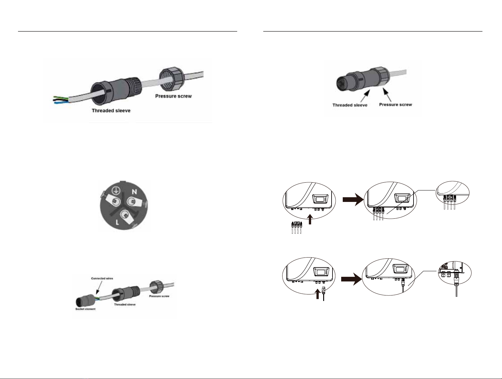
1) Put the threaded sleeve and pressure screw of AC wring terminal and the AC wire.
2) Wire the AC wire refers to below instructions.
Fig.3-34
Fig.3-35
3) Confirm all the wires should be screwed down.
4) Screw down the threaded sleeve and the pressure screw.
5) The AC connection finished.
Fig.3-36
Fig.3-37
3.6.4.3 DC/AC terminal connection:
1) Make sure that the DC/AC breaker is switched off.
2) Insert the DC+/- wiring terminal into corresponding DC+/- terminal.
Fig.3-38
3) Insert the AC wiring terminal into the AC terminal.
4) Switch on the AC breaker.
5) Switch on the DC breaker.
Installation
Screw the green-yellow wire to the ground terminator in the AC Connector
Screw the blue wire to the N(Natural) terminator in the AC Connector.
Screw the brown wire to the L(Line) terminator in the AC Connector.
DC1+ DC1- DC2- DC2+ AC
OUTPUT
DC1+ DC1- DC2- DC2+ AC
OUTPUT
AC
OUTPUT
A1 B2B1 A2
+5V
GND
098-06013-00
710-06013-00
1 9
210
CN1
U4
85
4
U3
LD2
LAB1
1
J1
ATT
U2
U1
TVS1
R7
R6
R5
R4
R2
R1
LD1
JP2
12
JP1
C7
C4
C2
R9
R10
C3
Fig.3-39
AC
OUTPUT
AC
OUTPUT

A1 B2B1 A2
+5V
GND
098-06013-00
710-06013-00
1 9
210
CN1
U4
85
4
U3
LD2
LAB1
1
J1
ATT
U2
U1
TVS1
R7
R6
R5
R4
R2
R1
LD1
JP2
12
JP1
C7
C4
C2
R9
R10
C3
Installation
26
Fig.3-40 Fig.3-41
27
3.6.4.4 Connect RS485 as per the following steps.
Fig.3-42
Fig.3-43
Installation
7)Start the monitor software on the PC and start to communicate.
2) Remove the waterproof cover from the RS485 communication waterproof
terminal, lead the cable through the cover and then to the device via the
waterproof terminal.
3) Estimate the cable length to the terminal, peel off the cable as pre the length
of the metal section of the tube type pre-insulated terminal, and press on the
terminal by a pair of wire end-sleeve pliers reliably.
1) Remove the 6 screws on the inverter bottom cover by wrench, and open the
bottom cover.
4) Press down the top of the terminal by a flat screw driver, insert the cable into
the terminal A/B.
Fig.3-45
A1 B2B1 A2
+5V
GND
098-06013-00
710-06013-00
1 9
210
CN1
U4
85
4
U3
LD2
LAB1
1
J1
ATT
U2
U1
TVS1
R7
R6
R5
R4
R2
R1
LD1
JP2
12
JP1
C7
C4
C2
R9
R10
C3
A1 B2B1 A2
+5V
GND
098-06013-00
710-06013-00
1 9
210
CN1
U4
85
4
U3
LD2
LAB1
1
J1
ATT
U2
U1
TVS1
R7
R6
R5
R4
R2
R1
LD1
JP2
12
JP1
C7
C4
C2
R9
R10
C3
5)Cover the bottom cover of the inverter.
Fig.3-44
6) Connect the other side of the communication cable to the 485/USB
connector and then connect the USB to the PC.

28
3.6.5 Earthing requirement
29
4Trial operation
4.1 Check before operation
4.1.1 Check for reliability of mechanical installation
4.1.2 Check for connecting cables
4.1.3 Electrical check
Make sure the grid parameters are complying with the inverters parameters.
4.2 Electrify the inverter
Installation Trial operation
Warning
Caution
Necessary safety check must be performed before the
inverter is electrified for trial operation!
The inverter is a device with no transformer, neither the
positive nor the negative pole of the PV assembly DC side
can be earthed, or the inverter will not work normally, or even
be damaged irreversibly.
In Song series PV power generating system, all device shells, assembly supports
and the GND terminal of the inverter must be safety and reliably earthed. Check if the inverter is firmly installed and if all bolts are reliably tightened. For
an inverter installed on a metal supporter, make sure each bolt is tightened and
support has enough load bearing capacity.
Check if all cables in the system are firmly connected without any missed or
wrong connection, and especially check if all positive and negative poles are
correct. If a DC switch is equipped on the inverter, the DC switch shall be turn
to the “OFF” state.
Make sure the DC input voltage of the inverter is lower than 550V (with the
temperature decrease of the PV array, the open circuit voltage will be
increased, so a residual voltage at the low temperature must be put into
consideration).
The inverter can be started up as per the following steps after all testing and
checking steps are performed.
Switch on the DC breaker, and turn the DC switch to the “ON” state if a DC
switch is equipped on the inverter.
Switch on the AC breaker.
See Part 5 of this manual for “Human-machine interaction” after the inverter is
started up. If enough power energy can be generated in the solar array, the
inverter will be started up automatically, and LCD will display the normal status
which means the inverter is successfully started up. If the inverter is not
normally started up, please refer to Part 6 “Troubleshooting and maintenance”.
This manual suits for next models
5
Table of contents
Other Thinkpower Inverter manuals

Popular Inverter manuals by other brands


ABB
ABB UNO-DM-TL-PLUS-US product manual

Growatt
Growatt MID 33-50KTL3-X2 quick guide

Apex Digital
Apex Digital APEX-E-P3-5000L user manual

Generac Power Systems
Generac Power Systems Guardian 004721-0 owner's manual

Winco
Winco Home power HPS12000HE Installation and operator's manual

MAC3
MAC3 E-Power e-MM user manual


