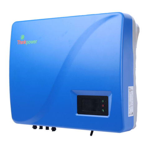
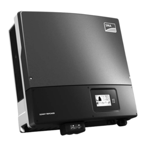
Thinkpower EPH4KTL User manual

啥
一
?
i t`
嘈
!;、K
^/
t
“`l "\
\
Three Phase Hybrid Inverter
User Manual
- Installation
-Operation
-Maintenance

Contents
21

&)
心?c
必
怂
士-
互
心Caution
@
心?c
12

一
回一口
AC
-------· Com
妇
乙
|妇
扁圆
扁圆
问圆
户
「—— 妇
问回
问回
34

Introduction Installation
65
1.3.4.1) In the valley level, the grid and PV charge the batteries.(Fig:1.3.4.1)
Fig:1.3.4.1
1.3.4.2) In the flat stage,if the PV is sufficient,the battery can be charged(Fig:1.3.4.2A); if
the PV is insufficient, Priority is for loads(Fig:1.3.4.2B).
Fig:1.3.4.2A Fig:1.3.4.2B
1.3.4.3) In the peak level.
Fig:1.3.4.3(A)(PV is sufficient) Fig:1.3.4.3(B)(PV is insufficient)
SYSTEM EPSGRID FAULTCOM METER
SYSTEM EPSGRID FAULTCOM METER
SYSTEM EPSGRID FAULTCOM METER
SYSTEM EPS
GRID FAULT
COM METER
1
2
3
SYSTEM EPSGRID FAULTCOM METER
2 Installation
2.1 Unpacking and Checking
On receiving the inverter, please check before installation to make sure all the
components as below are not missing or damaged.
2.2 Unacceptable Installations
Please avoid the following installations, which will damage the system or the inverter.
SYSTEM EPSGRID FAULTCOM METER
Backup Loads
SYSTEM EPSGRID FAULTCOM METER
Battery
Hybrid Inverter(A)
SYSTEM EPS
GRID FAULTCOM METER
Battery
Hybrid Inverter
SYSTEM EPSGRID FAULTCOM METER
Hybrid Inverter(B)
SYSTEM EPSGRID FAULTCOM METER
Hybrid Inverter(B)
Incompatible battery
×
× ×
Hybrid Inverter(A)
SYSTEM EPSGRID FAULTCOM METER
Hybrid Inverter(A)
SYSTEM EPSGRID FAULTCOM METER
Hybrid Inverter(B)
×
Solar
SYSTEM EPSGRID FAULTCOM METER
Hybrid Inverter(A) ×
Back-up On-Grid
Generator
SYSTEM EPSGRID FAULTCOM METER
Hybrid Inverter(A) ×
Back-up
Grid
Single PV cannot connect to two inverters.
Back-Up cannot connect in parallel.
On-Grid or Back-Up side cannot connect to
any Generator.
Battery Input cannot connect to Incompatible battery.
Back-Up side cannot connect to Grid.
One Battery Bank cannot connect to multiple inverters.
Inverter×1 Smart Meter×1
with 3 CT
Positive PV
connector×2
AC Connector×2
Positive PV
connector×2
Positive Bat
connector×1
Positive Bat
connector×1
Installation Screw
packet User manual×1
RJ45 Connector×2

2.3 Mounting
2.3.1 Requirements For Mounting
The installation of the inverter should be protected under shelter from direct sunshine or
any bad weather conditions as shown below:
Fig.2.1
The inverter should be installed in a cool & dry place with temperature from -25 to
60 (High ambient temperature will cause the inverter’s power derating).
The inverter LCD should be leveled with eyes and with enough space in the front for
inspection.
The inverter should be installed on a vertical wall or within 15°at most if backwards to the
wall
Fig.2.2
To avoid burning and electric shock, the inverter should be installed beyond reach of
children.
Make sure the installation position does not shake.
MAX 15°
No Direct Sunlight No Exposure to Rain and Snow Direct Sunlight ×Exposure to Rain and Snow ×
Leave enough space around the inverter as shown below:
Fig.2.3
2.3.2 Mounting The Inverter
Step 1: Use the positioning the cardboard as template to drill 4 holes on walls.
Fig.2.4
Step2: Fix the trapping screws to the wall tightly.
Fig.2.5
Position Min.Size(CM)
Front 40CM
Lateral
Top
Bottom
40CM
40CM
50CM
40CM
40CM 40CM
50CM
87
Installation Installation

Installation
9
Installation
10
Step3: Lift and hang the inverter on the wall,lock the nuts, and fix the machine.
Fig.2.6
2.4 Electrical Connection
2.4.1 System Wiring Diagram
General wiring diagram of EPH series hybrid inverter.
Fig.2.7
2.4.2 Overview Of The Electrical Connecting Part
Fig.2.8
2.4.3 PV Connection
2) The voltage, current and power ratings of the PV strings are within the allowable range
of the inverter. Please refer to the Technical Data Sheet for voltage and current limits
Before connecting PV panels/strings to inverter, please make sure:
1) Use the right PV connectors in the accessory box.
.
3) Make sure the PV switch of the inverter is in the “OFF” position during wiring.
4) PV strings could not connect to EARTH conductor.
STEP1:
Assemble the PV connectors from the accessory box.(PV cable must be firmly crimped
into connectors)
BMS
ON
OFF PV1
+
-
PV2 Battery
+
-
+
-
Meter
DRED
WIFI
Power Back-up On-Grid
Fig.2.9
STEP2:
Connect the PV connectors to the inverter. There
will be a click sound if connectors are inserted correctly
into PV plugs.
Fig.2.10

Installation
11 12
Installation
2.5 Battery Connection
Fig.2.1
Battery connection diagram
1
1) Use the right BAT connectors in the accessory box.
2) Choose 4 to 6 mm²(AWG 10) tin-plated cable to connect the battery and the inverter.
3) Make sure battery switch is off and battery nominal voltage meets EPH series
inverter’s specification before connecting battery to inverter.
STEP1:
Assemble the battery connectors from the accessory box.(battery cable must be firmly
crimped into connectors)
Fig.2.12
BMS
+-
CAN
Batery Power
BMS
ON
OFF PV1
+
-
PV2 Battery
+
-
+
-
Meter
DRED
WIFI
Power Back-up On-Grid
STEP2:
Connect the battery connectors to the inverter.
There will be a click sound if connectors
are inserted correctly into battery plugs.
Fig.2.13
STEP3:
Connect the BMS cable between battery and inverter, insert the RJ45 connector with
water-proof cap into the port marked “BMS” on inverter and fasten the cap. Then insert the
other end of the cable into the battery port.
Position Color
1Orange&white
Orange
Green&white
Blue
Signel Name
485_A2
NC
Blue&white
Green
Brown&white
Brown
2
3
4
5
6
7
8
485_B2
CAN_H
CAN_L
NC
NC
NC
Fig.2.14

Installation
14
Installation
13
The similar way to assemble the EPS connector, pin , pin and pin are live lines, pin N
is neutral.
Fig.2.16
STEP2:
Connect the grid connector and the EPS connector
to the inverter. Just follow the markings on the
inverter to connect them correctly.
2.7 Power key and Declara n for EPS Loads
Fig.2.17
The power button on the rear panel is only used for EPS function.
※When mains power does not exist and EPS function is enabled, press and hold for 3
seconds, the inverter will enter backup mode;
※When inverter operates in backup mode, press and hold for 3 seconds, inverter will exit
backup mode;
※When inverter gives an alarm and shutdown in backup mode, press and hold for 3
seconds, inverter will clear alarm.
※Inductive load: a non-frequency conversion air conditioner within 1.5P can be connected
to EPS side. Two or more may cause EPS output unstable.
Do not connect 3-phase inductive load(like motor) without Neutral line to EPS side.
※Capacitive load: Total power <=0.6*nominal power of model.
2.8 Smart meter connection
Please Refer to the connection instructions in the meter
box for connection
2.6 Grid & EPS Connection
Use the AC connectors from accessory box for grid and EPS connection. An external AC
breaker(32A) is needed for on-grid connection to isolate from grid
when necessary .
STEP1:
Note: Pi
Assemble the grid connector. Follow the markings on the
connectors, make sure 3L/N/PE lines are connected correctly.
nconnect to grid phase A, pin c onnect to
phase B and pinL to phase C. Fig.2.15
w

Operating of the Inverter
15 16
Operating of the Inverter
3 Operating of the Inverter
3.1 LED and LCD Display
The LED indicators are shown as blow:
LED Status Explanation
SYSTEM ON System is powered up
OFF System is not powered up
GRID
ON Grid is normal
OFF Grid loss
FLASH Grid is abnormal
EPS ON Inverter in offline mode, EPS is
active
OFF Inverter is not in offline mode
COM ON WIFI module connected
OFF WIFI module not connected
METER ON Smart meter communication OK
OFF Smart meter communication fail
FAULT
ON Alarm occurred and inverter stop
work
OFF No Alarm
FLASH Alarm occurred but inverter still work
The LCD display shows the detailed information of the inverter
PV12
A
C
A
B
C
B
A
B
C
D
E
F
G
HIJK
L
M
N
O
P
Q
R
Position Description
A It indicates the power output amount of total and today alternately. Unit: kWh or MWh
B PV panels indicator
C PV1,PV2 panels parameters. Voltage and current are displayed alternately.
D Total PV power
E Battery parameters. Voltage and current are displayed alternately.
FBattery power
G Battery indicator
H SOC of battery
I Current time
J
Power flow array of battery. When it towards battery, it means charging; when it towards inverter,it
means discharging.
K Default as current date. When an error occurs, fault code will be displayed alternately.
LLoads indicator
MLoads power consumption of each phase
NLoad parameters. Voltage and current of each phase are displayed alternately.
O Power export or import of each phase
P Grid indicator
Q Grid parameters. Voltage and current of each phase are displayed alternately.
R Power flow array of load

巨·
二了
210?.
=它;亡
二
·-
~
扣山 比
s”nUp
三
.一
G I
,'
In
M.
。*
9沁田
Both web and APP are available, this part shows monitoring and setting on web page,
The default setting is the most common, and users generally do not need additiona
Monitoring and Setting
settings.
弩“
.
。
On the plant list page, click plant name,
user can view plant detail information.
i,
}1
g0
}
o
_
18

~匕二3
~ 田
`E,一
切'"
`,_
芷
户L
一·
(

c
Three-phase unbalanced oput
21
,
22

Operating of the Inverter
●Peak time discharge
Peak time discharge mode Automatic power regulation
*Peak time discharge power(500-10000W) 3000
The peak time discharge setting is only effective when the user selects the peak shaving
and valley filling mode. During the peak time, the default setting is that the system automat-
ically adjusts the discharge power according to the household power detected by the smart
meter; If the smart meter is not installed, the user can select a fixed discharge power
according to the approximate power consumption.
●Battery backup mode charging setting
Charging with grid in storage mode
*Storage mode charge SOC(20-100%) 40
*Storage mode charge power(500-10000W) 4000
The battery backup mode charging setting is only effective when the user selects the
battery backup working mode. You can set whether to turn on the mains power to charge
the battery, and the charging power and battery charging cut-off SOC.
23
Trouble Shooting
4 Trouble Shooting
This part introduces the common fault and solving steps,provides troubleshooting
methods and skills to the user, and helps the user identify and solve some common faults of
the inverter.
Protection Description Recommended solution
code
Check the configuration of the PV
P001 PV over voltage protection panels
P002
P003
P004
Battery over voltage protection
Insulation resistance low
Leakage current high
Check if battery volt larger than 600V
Check the insulation of PV panels
This error will reset itself.
P005
P006
Over temperature protection
Bus voltage unbalance
The inverter will recover automatically
when the temperature gets lower.
P007
P008 Bus voltage high
Bus voltage low
The inverter will recover automatically.
Check the connection of AC side.Make
P009
P010
P011
P012
P013
P019
P020
Grid and EPS are reversed
Grid relay open-circuit
Grid relay stick
On-grid mode bus soft start fault
MCU communication fault
Battery SOC low in on-grid
mode
Battery SOC low in EPS mode
sure the grid and EPS load are
connected to the ports on the inverter
correctly.
Shut down and restart .If it still can't be
auto-recover, please contact the
service.
Battery discharged to low level, it will
recover after charged automatically
P021 Battery voltage low
24

Trouble Shooting
P022
P023
P024
P025
P026
P027
Battery open-circuit
Battery SOC deadly low
BMS communication fault
No time interval setting for Peak
shaving and valley filling mode
Remote off
Smart meter communication
fault
Check the connection of battery and set
right battery SOC in each mode.Check
the battery for parameter settings.
Check the BMS communication cable
and BMS protocol setting
Check inverter work mode setting
Inverter turn off through monitoring
Check the communication cable for
smart meter and meter protocol
P033
P034
P035
P036
Grid voltage high
Grid voltage low
Grid frequency high
Grid frequency low Check if grid fails or not connected well
P037
P038 Islanding protection
Grid wave loss
P039
P040
P041
DC injection high
Utility not three phase
Phase sequence fault
The inverter will recover automatically.
Check if grid cable well connected
Reverse connection order of L2 and L3
cable
P042 PLL error The inverter will recover automatically.
Decrease EPS loads to make sure the
P048 EPS overload total loads power is lower than EPS
nominal output power, press power key
more than 3 seconds to clear alarm
P049
P050
P051
P052
EPS output voltage high
EPS output voltage low
EPS mode bus soft start fault
Inv soft start fault
Check if EPS over load, press power
key more than 3 seconds to clear alarm
P053 EPS load short circuit
25
Trouble Shooting
P059 Battery current limited
P060 Inv trip The inverter will recover automatically.
P061 Transient trip
P062 Bus trip
If you meet any problem that you cannot solve by yourself, please contact with your local
distributor or our company.
26

28
Technical Data Technical Data
5 Technical Data
Model EPH4KTL EPH5KTL EPH6KTL EPH8KTL EPH12KTEPH10KTL L
Input(PV)
Max PV Power 5500W 6500W 7500W 9500W 11500W 13200W
Max PV Voltage 1000Vd.c
MPPT voltage range 200~850Vd.c
Max input current/per string 13A/13A
Number of MPP trackers
Number of input string
2
1
Battery Input
Battery Type Li-Lon
Battery voltage range 130~700V
Max charge/discharge current 25A/25A
Charge strategy for Li-lon Battery Self-adaption to BMS
AC Output (On-Grid)
AC nominal power 4000VA 5000VA 6000VA 8000VA 10000VA 12000VA
Max AC apparent power 5000VA 5500VA 7000VA 8800VA 11000VA 13200VA
Max output current 8 10 12 15 17 20
Nominal AC output 50/60Hz;400/350
AC output range 45/55Hz;280~490Vac(Adj)
Power factor 0.8leading~0.8laging
Harmonics <3%
Grid type 3W/N/PE
Three-phase unbalance output 0~100% 0~80%
AC Output Back-up
Max AC apparent power 4000VA 5000VA 6000VA 8000VA 10000VA 10000VA
Norminal Output Voltage 400/380
Norminal Output Frequency 50/60
Output THDV (@Linear Load) <3%
27
Efficiency
Max conversion efficiency 98.0% 98.0% 98.2% 98.2% 98.2% 98.2%
European efficiency 97.3% 97.3% 97.5% 97.5% 97.5% 97.5%
MPPT efficiency 99.9% 99.9% 99.9% 99.9% 99.9% 99.9%
Safety and protection
DC reverse-polarity protection yes
DC breaker yes
DC/AC SPD yes
Leakage current protection yes
Insulation Impedance Detection yes
Residual Current protection yes
Output short circuit protection yes
Bat reverse connection protection yes
General Parameters
Dimensions (W/H/D) 548*444*184mm
Weight 27kg
Operating temperature range -25 ~+60
Degree of protection IP65
Cooling concept Natural convection
Topology Transformerless
Display LCD
Humidity 0~95%,No condensation
Communication GPRS/WiFi
CAN/RS48BMS communication 5
Meter communication RS485
This manual suits for next models
5
Table of contents
Other Thinkpower Inverter manuals
Popular Inverter manuals by other brands
Dometic
Dometic Go Power! Solar Flex Kit GP-FLEX-55 user manual
dolycon
dolycon CT120G MINI Series user manual
Generac Power Systems
Generac Power Systems Guardian Elite 05402 Specification sheet

Hoymiles
Hoymiles HM-1200 user manual
SOLINTEG
SOLINTEG INTEG M MHS Series Quick installation guide

Zamp Solar
Zamp Solar ZS-8AW user manual
