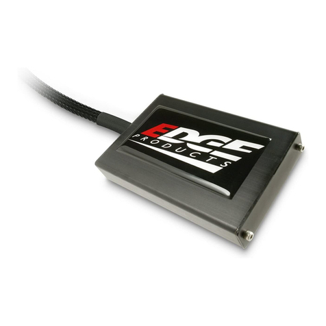
ThinkRF D4000 User manual

D4000
40 GHz RF Downconverter/Tuner
User Guide
Version 1.0
July 2020
Docu ent no. 75-0044-200731
Copyright © 2020 thinkRF Corporation, all rights reserved.
All product na es are trade arks of their respective co panies.
This docu ent contains infor ation that is proprietary to thinkRF Corporation.

Important notice
The infor ation in this
guide is furnished for
infor ational use only
and is subject to change
without notice. thinkRF
Corporation assu es no
responsibility or liability
for any errors or
inaccuracies that ay
appear in this docu ent.
No part of this
publication ay be
reproduced, published,
stored in an electronic
database, or trans itted,
in any for or by any
eans, electronic,
echanical, recording,
or otherwise, for any
purpose, without the
prior written per ission
of thinkRF Corporation.
Trademarks
thinkRF, the thinkRF
logo and D4000 are
trade arks of thinkRF
Corporation.
All other brand or
product na es are
trade arks or registered
trade arks of their
respective co panies or
owners.
thinkRF Corp
390 March Road
Kanata, ON K2K 0G7
(613) 369-5104
HARDWARE WARRANTY AND LIMITATI N F LIABILITY
Read this warranty carefully before you use the product.
D4000 40 GHz RF Downconverter/Tuners are warranted for work anship and
aterials for a period of one (1) year fro the date of ship ent as identified by the
Custo er’s packing slip or carrier waybill. thinkRF reserves the right to void the
warranty on any equip ent that has been altered or da aged due to Custo er
negligence, unauthorized repair, isuse of equip ent, evidence of physical or
environ ental da age, transportation abuse or re oval of any thinkRF identification
labels or serial nu bers.
It will re ain the responsibility of the Custo er, having obtained a Return Material
Authorization (RMA) and shipping instructions fro thinkRF, to return, at the
Custo er's expense, the defective unit to thinkRF’s repair facilities. thinkRF will
incur shipping charges for the return of warranty repaired equip ent. The RMA
nu ber can be secured by contacting thinkRF Custo er Service and Support
([email protected] ). If the product does not fall within thinkRF’s warranty period
or the product is found to be functioning as designed, then under the ter s of
thinkRF’s warranty policy, all costs of repairs and shipping will be charged directly to
the Custo er. thinkRF will warrant repaired units for a period of 90 days fro date
of ship ent fro thinkRF to the Custo er. If the re aining period on the original
hardware warranty is greater than 30 days, then thinkRF will honor this re aining
warranty period.
thinkRF EXPRESSLY DISCLAIMS ALL OTHER WARRANTIES AND CONDITIONS,
WHETHER EXPRESS OR IMPLIED, INCLUDING WITHOUT LIMITATION,
WARRANTIES, CONDITIONS OR REPRESENTATIONS OF WORKMANSHIP,
MERCHANTABILITY, FITNESS FOR A PARTICULAR PURPOSE, DURABILITY, OR
THAT THE OPERATION OF THE HARDWARE OR LICENSED SOFTWARE WILL
BE ERROR FREE. IN NO EVENT WILL thinkRF BE LIABLE FOR INDIRECT,
SPECIAL, INCIDENTAL, OR CONSEQUENTIAL DAMAGES.
USE F PR DUCTS IN HIGH RISK ACTIVITIES
thinkRF PRODUCTS ARE INTENDED FOR STANDARD INDOOR COMMERCIAL
USE. WITHOUT THE APPROPRIATE NETWORK DESIGN ENGINEERING, THEY
MUST NOT BE USED FOR ANY “HIGH RISK ACTIVITY”, as described in this
paragraph. Custo er acknowledges and agrees that the products supplied
hereunder are not fault-tolerant and are not designed, anufactured or intended for
use or resale as on-line control equip ent in hazardous environ ents requiring fail
safe perfor ance including but not li ited to the operation of nuclear facilities,
aircraft navigation or co unication syste s, air traffic control, direct life support
achines, or weapons syste s, in which the failure of products could lead directly to
death, personal injury, or severe physical or environ ental da age, all of which are
exa ples of “High Risk Activity”. thinkRF AND ITS SUPPLIERS EXPRESSLY
DISCLAIM ANY EXPRESS OR IMPLIED WARRANTY OF FITNESS FOR HIGH
RISK ACTIVITIES.

Table of Contents
Preface ............................................................................................................................ 5
Audience....................................................................................................................5
Conventions..............................................................................................................5
btaining the Latest Documentation and Software..............................................6
Document Feedback.................................................................................................6
btaining Technical Assistance..............................................................................6
verview of the D4000 .................................................................................................. 7
Getting Familiar with the D4000..............................................................................7
The Front Panel............................................................................................................................ 7
The Rear Panel............................................................................................................................ 8
The Underside.............................................................................................................................. 8
Precautions and peration Consideration ................................................................. 9
Preventing Electrostatic Discharge Damage.........................................................9
Preventing RF Connector Damage.........................................................................9
2.92 Fe ale Connector....................................................................................................... 10
SMA Connectors......................................................................................................................... 10
peration Consideration and Maintenance.........................................................10
Setting Up the D4000 ................................................................................................... 11
Unpacking the Box..................................................................................................11
Connecting the Ethernet and Cables....................................................................11
Use of D4000 with External 10 MHz Reference....................................................12
Interfacing with the D4000 .......................................................................................... 13
Network Application Access Methods..................................................................13
SCPI Raw................................................................................................................................... 13
Establishing Ethernet Connection with D4000....................................................14
Changing the Method of IP Address Allocation for D4000.................................14
Device Reset ................................................................................................................. 15
Reset to Factory IP Configuration.........................................................................15
Restore to Factory Settings...................................................................................15
Status Indicator LED ................................................................................................... 16
Hardware Reference .................................................................................................... 18
System Specifications............................................................................................18
2.92 mm and SMA Connectors..............................................................................18
RJ-45 Ethernet Port Pinout....................................................................................19
RJ-45 Straight-Through Ethernet Cable...............................................................19

Preface
Preface
This preface describes the audience for, the organization of, and conventions used in this
docu ent. It also identifies related docu entation and explains how to access electronic
docu entation.
Audience
This docu ent is written for technical people who have basic understanding, fa iliarity
and experience with network test and easure ent equip ent.
Conventions
This section describes the conventions used in this docu ent.
Grayed-out Font
Indicates a co and or a feature is not yet available in the current release.
Courier Font
Illustrates this is an exa ple for a co and or a concept.
Light Blue Font
Contains hyperlink to the referenced source that can be clicked on.
Normal Bold Font
When used within a sentence or a paragraph, it e phasizes an idea to be paid attention
to particularly.
Red Font
Conveys special infor ation of that section.
Note: This sy bol eans take note. Notes contain helpful suggestions or references to
additional infor ation and aterial.
Caution: This sy bol eans be careful. In this situation, you ight do so ething that
could result in equip ent da age or loss of data.
Warning: This sy bol eans danger. You are in a situation that could cause bodily
injury. Before you work on any equip ent, be aware of the hazards involved with
electrical circuitry and be fa iliar with the standard practices for preventing accidents.
5 thinkRF D4000 RF Downconverter/Tuner User Guide

btaining the Latest Documentation and Software
Please visit our website's resource page at http://www.thinkrf.co /resources/ to obtain the
latest docu entation and releases of new fir ware and software.
Document Feedback
Please send your co ents about this docu ent or our other docu entation to
Thank you, we appreciate your co ents.
btaining Technical Assistance
For all custo ers who hold a valid end-user license, thinkRF provides technical
assistance 9 AM to 5 PM Eastern Ti e, Monday to Friday. Contact us by filling out the
for listed on http://www.thinkrf.co /support/.
Before contacting Support, please have the following infor ation available:
D4000 serial nu ber, product version (and options if available), which are
located on the identification label on The Underside of the D4000.
The fir ware version running on the D4000 (use *IDN? co and).
If applicable, the versions of thinkRF software you are using or any third-party
applications.
The operating syste and version you are using.
For any other infor ation, contact thinkRF at:
thinkRF Corporation
390 March Road
Kanata, ON K2K 0G7
+1.613.369-5104
www.thinkrf.co
thinkRF D4000 RF Downconverter/Tuner User Guide 6

verview of the D4000
verview of the D4000
Note: This is a living and evolving document. We welcome your feedback.
The features and functionality described in this section may exist in the current product or
are scheduled for a future product release.
D4000 40 GHz RF Downconverter/Tuner is used to convert RF signals in the range of 24-
40 GHz down to an inter ediate frequency (IF) of 1.536 GHz. This is designed to extend
the functionality of existing spectru analyzers that can operate at 1.536 GHz to easure
and analyze 5G signals in the range of 24-40 GHz band.
Getting Familiar with the D4000
This section provides infor ation about the front and rear panels, connection ports and
identification label of the D4000 RF Downconverter/Tuner.
Note: The type and place ent of connectors and co ponents on the panels and the
case ay vary depending upon the product version.
The Front Panel
The front panel of the D4000 contains, fro left to right:
7 thinkRF D4000 RF Downconverter/Tuner User Guide

•+12 VDC LEMO connector, 4 pin
•RF IN port, 2.92 fe ale connector, +10 dB Max, +10 VDC Max
•IF OUT port, fe ale bulkhead SMA connector
•10 MHz IN port, fe ale bulkhead SMA connector, 0 dB Min, +10 dB Max
•10 MHz OUT port, fe ale bulkhead SMA connector
•RST, factory reset button
•STS/PWR/EXT REF, Status LEDs
•CTRL, GPIO port, D-Sub high density receptacle 15 Position
•RJ-45 Ethernet port
The Rear Panel
The rear panel of the D4000 contains a power switch, and a gore vent for getting
oisture out of the device.
The Underside
The underside of the D4000 provides an identification label, as illustrated below. The
label on your product ay vary depending on your product variant and version.
The product “Version” nu ber is i portant for identifying which fir ware can be used to
update your product. The “Options” nu ber is to identify which product odel you have,
see D4000’s datasheet if the Options is not NONE.
thinkRF D4000 RF Downconverter/Tuner User Guide 8

Precautions and peration Consideration
Precautions and peration Consideration
Ensure that you read and understand the following infor ation about safety and
electrostatic discharge before you unpack and set up the D4000.
Warning: Only trained and qualified personnel should be allowed to install or replace this
equip ent. Read the installation instructions before you connect the syste to its power
source.
Preventing Electrostatic Discharge Damage
Electrostatic Discharge (ESD) is a single-event, rapid transfer of electrostatic charge
between two objects, such as an operator and a piece of electrical equip ent. ESD can
occur when a high electrostatic field develops between two objects in close proxi ity.
ESD occurs when electronic co ponents are i properly handled and is one of the ajor
causes of device failures in the se iconductor industry.
Electrostatic discharge is ore likely to occur with the co bination of synthetic fibers and
dry at osphere. Always follow these steps to prevent ESD.
Warning: Never open the front or rear panels of the D4000 as personal injury ay result
and opening the chassis will void the warranty. There are no user-serviceable parts
inside. Always contact thinkRF support for service through the online support for at
http://www.thinkrf.com/support/.
Caution: To prevent ESD, wear an ESD-preventive wrist strap that you provide, ensuring
that it akes good skin contact.
Caution: Do not touch any exposed contact pins or connector shells of interface ports
that do not have a cable attached. If cables are connected at one end only, do not touch
the exposed pins at the unconnected end of the cable.
Preventing RF Connector Damage
When connecting to an RF connector, whether it is SMA or other connectors, it is
i portant that proper care and connector connection practice is used to prevent
irreversible da age to the connector and its port.
Caution: When ating/de ating the connectors,
- Do: align the ating connectors properly to prevent da aging the center pin, ake
preli inary connection by using fingers, use correct torque spanner for the final
connection
- Do not: apply bending force to connection, over-tighten to a connector on the jack or
9 thinkRF D4000 RF Downconverter/Tuner User Guide

overturn point of the torque wrench. Using incorrect torque wrench, wrench, pliers or even
your hand to over-tighten a connector can cause per anent da age to a D4000.
2.92 mm Female Connector
Caution: Use only 2.92 Male connector as the ating part to the D4000’s RF IN port.
NLY use 2.92 cables and connectors.
Use only a proper torque wrench with torque setting intended for a 2.92 Male
connector (not the sa e one for a SMA connector). The reco ended torque setting is
100 N.c (8.9lbs.in). An exa ple of a torque wrench that can be used for this is Huber-
Suhner P/N 74 Z-0-0-21.
SMA Connectors
The reco ended torque setting for all SMA connectors is 45 N.c (4lbs.in). An
exa ple of a torque wrench that can be used for this is Huber-Suhner P/N 74 Z-0-0-79.
peration Consideration and Maintenance
The D4000 should be operated only within its specified operation te perature and
specification of 14°F to 131°F (-10°C to 55°C). The ideal operating te perature for
opti u perfor ance is between 68°F to 77°F (20°C to 25°C).
Caution: Do not expose the device to direct sunlight or radiation fro other sources of
heat.
So e regular aintenance is needed to aintain the unit in its good working state. This
includes inspect and keep all the connectors clean, especially the threads by using, for
instance, Lint Free cloth or Q-tip with Isopropyl alcohol.
thinkRF D4000 RF Downconverter/Tuner User Guide 10

Setting Up the D4000
Setting Up the D4000
Unpacking the Box
The following table lists the ite s that co e with your D4000. If any of the ite s are
issing or da aged, please contact your thinkRF custo er service representative.
D4000 Shipping Box Contents:
•D4000 RF Downconverter/Tuner
•Power supply – with barrel connector
•Power cord – Country specific by Type
•Ethernet cable
•Thank you/Reference card
Connecting the Ethernet and Cables
Follow the steps below to connect up the D4000 ports. The diagra bellow illustrates the
setup steps.
1. Before connecting D4000 to a spectru analyzer (SA), if instead of the provided
+12 VDC power adapter, a power source or power pack is used, then first power
up the power source device and set the voltage to +12 VDC and 3 A in.
Connect the power supply source to D4000’s LEMO power connector.
11 thinkRF D4000 RF Downconverter/Tuner User Guide

Caution: Do not supply a power source exceeding +15 VDC to the D4000. It can cause
per anent da age to the device.
2. Connect one end of the Ethernet cable to the D4000's Ethernet port and the
other end to an Ethernet port on the SA or a co puter.
Caution: For the following RF connectors, see Preventing RF Connector Da age section
for i portant cautions and torque suggestion.
3. Connect the Antenna or an RF input source to the D4000’s RF IN port.
4. Connect the SMA connector end of the cable co ing fro D4000’s 10 MHz OUT
port to the SA’s External IN port. I portant to see Preventing RF Connector
Da age and its SMA Connectors section for caution and torque suggestion.
5. Connect the SMA connector end of the cable co ing fro SA’s RF IN port to the
D4000’s IF OUT SMA port.
Connecting to D4000’s 10 MHz IN port is optional or on per needed basis for clock
synchronization. See Use of D4000 with External 10 MHz Reference for ore
infor ation and i portant cautions.
6. Connect the auxiliary GPIO to SA’s control port for controlling (Future feature)
Use of D4000 with External 10 MHz Reference
The thinkRF D4000 can be synchronized with the use of an external 10 MHz reference,
for exa ple, fro an external oscillator or fro the digitizer section of the data acquisition
syste .
As well, this 10 MHz is redistributed within the D4000 and sent to the 10 MHz OUT SMA
connector for use by external equip ent that needs a 10 MHz reference source.
To set the D4000 to use the external 10 MHz reference, send the SCPI co and
:SOURce:REFerence EXT (Refer the D4000 Progra er’s Guide for ore details).
Cautions:
- When the external 10 MHz IN reference is used, its reference level ust be between 0
dBm and +10 dBm.
- The axi u power level to the D4000’s 10 MHz IN is +10 dB . Exceeding this value
ight degrade the product perfor ance.
- The 10 MHz reference source to the 10 MHZ IN port ust be powered down prior to
powering down the D4000.
- See Preventing RF Connector Da age and its SMA Connectors section for i portant
caution and torque suggestion.
thinkRF D4000 RF Downconverter/Tuner User Guide 12

Interfacing with the D4000
Interfacing with the D4000
This section provides instruction for different ethods of accessing the D4000 via its
Ethernet port and obtaining its IP address.
The D4000 is network ready devices conveying SCPI (Standard Co ands for
Progra able Instru ents) co ands and data using the TCP/IP protocol via a Gigabit
Ethernet connection. Network application access is via SCPI Raw or SCPI Telnet.
Note: The SCPI co ands consist of network configuration, device status checking,
input filter selection, frequency settings, bandwidth and attenuation values, etc. To see a
co plete SCPI co and list for D4000, please refers to the D4000 Progra er’s Guide.
The D4000 also supports different ethods of obtaining its IP address including:
Dyna ic IP address allocation via the Dyna ic Host Configuration Protocol
(DHCP), which is applicable to a routed network topology that has a DHCP
server;
Static IP address allocation, which is applicable to any network topology.
Note: The D4000’s default factory configuration at the first power up or after a factory
reset is set to STATIC type with IP 192.168.1.2.
Network Application Access Methods
SCPI Raw
SCPI Raw uses a TCP/IP connection to establish a bidirectional link with ini al
overhead. Although it can be used as a co and line interface, it is better suited for use
with an application.
SCPI Raw is accessible via TCP port 5025, see the following figure.
thinkRF D4000 RF Downconverter/Tuner User Guide

Establishing Ethernet Connection with D4000
This section provides instruction on connecting the D4000 directly to a SA via their
Ethernet ports using an Ethernet cable.
To connect the D4000 directly to your SA:
1. If this is not the very first ti e connecting to the D4000, skip to the next step.
Otherwise, your SA’s Ethernet interface ust be configured first to use static IP
ode in order to work with the D4000’s factory default IP of 192.168.1.2. This
involves setting your SA to have an IP address of 192.168.1.x (x cannot be 2)
with a subnet ask 255.255.255.x and a gateway 192.168.1.x. If still not sure of
the setting, please contact your network ad inistration for valid settings.
2. Connect the Ethernet cable to both your SA's and the D4000 Ethernet ports.
3. Power up the D4000 if haven’t done so and wait until the status LED turns green.
4. Check to ensure that either your SA’s or the D4000 Ethernet’s jack LINK indicator
is illu inated. If it is not, then your SA ay not support auto atic crossover on
its Ethernet connection and you ay require an RJ-45 crossover Ethernet cable.
5. Choose one of the ethods entioned in Network Application Access Methods
to verify the established connection with the D4000.
6. With an assigned IP, the D4000 could now be controlled through SCPI
co ands described in the D4000 Progra er’s Guide docu ent.
7. If necessary, after establishing a successful connection, configure the D4000 to
your chosen ethod of IP allocation following the instruction in the Changing the
Method of IP Address Allocation for D4000 section.
Changing the Method of IP Address Allocation for D4000
This section provides instruction for re-configuring one IP address allocation type to
another for a D4000.
Notes:
- The D4000 is configured to STATIC IP 192.168.1.2 by factory default.
- Decide on whether you will be using static or dyna ic IP allocation. Regardless of
which ethod you choose, both your SA's and the D4000’s Ethernet interface ust be
configured for the sa e ethod of IP allocation.
If your D4000 is configured for static IP allocation, then it ay be reconfigured for
dyna ic IP address allocation using the :SYSTem:COMMunicate:LAN co and set
(see D4000 Progra er’s Guide docu ent).
If your D4000 is configured for dyna ic IP allocation, then it ay be reconfigured for
static IP address allocation either using the :SYSTem:COMMunicate:LAN co and set
(see D4000 Progra er’s Guide) or via a hardware factory reset. Using the hardware
factory reset to reconfigure to static IP allocation is the si plest ethod and is described
in the Device Reset section.
thinkRF D4000 RF Downconverter/Tuner User Guide 14

Device Reset
The pushbutton is accessible using a thin object such as a paperclip through the access hole.
It is used only during powerup to request a factory reset or restore. The pushbutton ust be
depressed before turning on power. The PWR LED turns solid yellow (Standby) to
acknowledge the keypress.
Reset to Factory IP Configuration
If for any reason you cannot connect to the D4000 via the Ethernet, then perfor ing this
following procedure will reset the D4000 network configuration to the factory installed
static IP configuration with IP address of 192.168.1.2.
Follow the steps below to reset your box.
1. Power off the D4000
2. Use a s all pin to access the reset button locating in The Front Panel of the
D4000
3. Press and hold while powering on the unit
4. Three fast flashing yellow LED light up on PWR LED
5. Release pin fro reset button within 10 seconds after powering up the unit
6. LED beco es nor al start-up sequences: PWR solid yellow, then solid green
7. Follow Establishing Ethernet Connection with D4000 section to setup the
connection
Restore to Factory Settings
If for any reason, unit need to be restore to factory load fir ware, then perfor ing this
following procedure will restore the D4000 to the factory load fir ware.
Follow the steps below to reset your box.
1. Power off the D4000
2. Use a s all pin to access the reset button locating in The Front Panel of
the D4000
3. Press and hold while powering on the unit
4. Three fast flashing yellow and a slow flashing yellow LED light up on
PWR LED
5. After powering up the unit for ore than 10 seconds, release pin fro
reset button
6. LED beco es nor al start-up sequences
thinkRF D4000 RF Downconverter/Tuner User Guide 15

Status Indicator LED
Status Indicator LED
The D4000 has a status (STS) indicator LED located on The Front Panel.
Using different colours and blink codes, the STS LED indicates the following device
conditions.
STS Indicator LED Internal Status
Green All internal power conditions are good and the device is
ready
Yellow The RF path and LOs are settling after a tune request
Red One or ore PLLs re ain unlocked past the expected
ti e
3 fast yellow blinks No network connection is present (e.g. unplugged, or
re ote peer is not connected)
2 fast, 1 slow yellow blinks The device has not received an IP address fro a
DHCP server
3 slow red Hardware failure
Off n/a
PWR Indicator LED Internal Status
Green All internal power conditions are good and the device is
ready
Yellow Device is in power down state
Red One of the power rails, other than the 3.3V rail, is
reporting a fault. This ay also indicate a icrocontroller
failure (e.g. unprogra ed or broken)
3 fast yellow blinks Factory Reset request is detected (pushbutton is
released in less than 10s)
2 fast, 1 slow yellow blinks Factory Restore request is detected (pushbutton held for
at least 10s)
Long short long yellow
blinks
A te perature sensor is reporting a te perature above
the warning threshold.
Long short long red blinks A te perature sensor is reporting a te perature above
the error threshold.
3 slow red Hardware failure
Off Not receiving power fro the power source
16 thinkRF D4000 RF Downconverter/Tuner User Guide

EXT REF Indicator LED Internal Status
Green Internal 10 MHz Lock
Yellow Overload Warning
Red Overload Error
3 slow Green External 10 MHz Lock
Off Not receiving power fro the power source
Fast blink is defined as 0.25 second long and slow blink is 0.75 second.
thinkRF D4000 RF Downconverter/Tuner User Guide 17

Hardware Reference
This section provides physical and perfor ance specifications, and port and cable
pinouts for the D4000.
System Specifications
The following table outlines the physical and electrical specifications for the D4000.
Description Design Specification
Di ensions (W x L x H) 7.6 x 7.6 x 1.6 in. (19.3 x 19.3 x 4.1 c )
Weight (approxi ately) Approx 1.7 Kg (3.7 lb)
Digital interface ports Ethernet 10/100/1000
Analog interface ports RF IN, IF OUT, 10 MHz IN and OUT
Input supply voltage 12 VDC +/- 5%
Input supply current 1.73 A at 12V
Power Consu ption 20.76 Watts
Operating te perature 14 to 131°F (-10 to 55°C)
Storage te perature -60 to 160°F (-51 to 71°C)
2.92 mm and SMA Connectors
The 2.92 and SMA connectors on the front panel are all fe ale jacks. The SMAs are
with 50Ω no inal i pedance. The following table outline the axi u and ini u
power level restrictions on these connectors.
Caution: Injecting signal levels that exceed the specifications described in the following
table will result in per anent da age to the RF Downconverter/Tuner.
Connector Name Direction Max Power Level Min Power Level
RF IN1in +10 dB 4, 10 Vdc4---
10 MHz IN2,3in +10 dB 40 dB 4
10 MHz OUT out +10 dB 4+5 dB in4
1 It is reco ended that the output of a signal source be verified with the use of a power eter
prior to connecting the source directly to the RF IN connector. It is best to inject signals equal to or
lower than -20 dB ; otherwise, an external attenuator should be considered to prevent da aging
the D4000. Additionally, any external signal sources connected to RF IN ust be turned on only
after powering on the D4000 and turned off prior to powering down the D4000.
2 The 10 MHz reference input ust be powered down prior to powering down the D4000. See also
the Caution Note of Use of D4000 with External 10 MHz Reference section on page 18.
thinkRF D4000 RF Downconverter/Tuner User Guide 18

3 To set the D4000 to use the external 10 MHz reference, apply a :SOURce:REFerence EXT
co and, see the D4000 Progra er’s Guide.
4 By design.
RJ-45 Ethernet Port Pinout
Pin Signal
1 BI_DA+
2 BI_DA-
3 BI_DB+
4 BI_DC+
5 BI_DC-
6 BI_DB-
7 BI_DD+
8 BI_DD-
RJ-45 Straight-Through Ethernet Cable
1 2 3 4 5 6 7 8 1 2 3 4 5 6 7 81 2 3 4 5 6 7 8 1 2 3 4 5 6 7 8
RJ-45 Crossover Ethernet Cable
thinkRF D4000 RF Downconverter/Tuner User Guide 19
1 2 3 4 5 6 7 8 1 2 3 4 5 6 7 81 2 3 4 5 6 7 8 1 2 3 4 5 6 7 8
1 2 3 4 5 6 7 81 2 3 4 5 6 7 8

Document Revision History
Document Revision History
This section su arizes docu ent revision history.
Document
Version
Release
Date
Revisions and Notes
v1.0 July 31, 2020 First release
20 thinkRF D4000 RF Downconverter/Tuner User Guide
Table of contents

