THK ET20 Series User manual
ET
High-precision multi-point positioning
with superior rotary performance
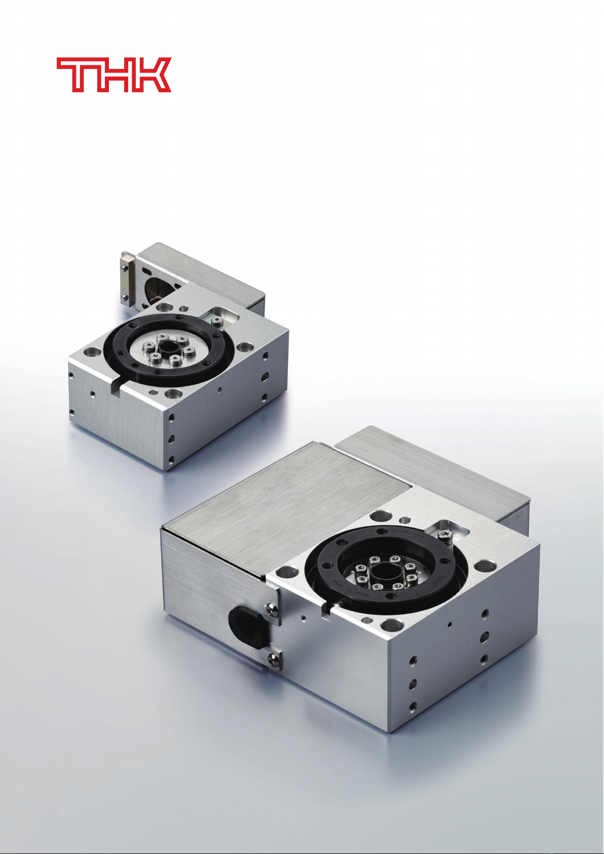
Thin Electric Turntable
ES/EC
○ Uses a ball screw to move with
higher precision than air cylinders.
○ Modularized structure reduces number
of components and both design and
assembly time.
○ Uses the Caged Ball LM Guide to
achieve long-term
maintenance-free operation (ES only).
Economy Series Electric Actuator
○ Capable of multi-point positioning,
opening and closing speed control,
and gripping force setting.
○ Smooth motion that withstands
repeated open/close operations.
○ Maintains gripping force even when
power is lost.
EG
Electric Gripper
○ Modularized structure reduces number
of components and both design and
assembly time.
○ Can be used in a horizontal,
wall-mounted, vertical,
or suspended orientation.
○ Optimal for high-precision positioning
and orthogonal-axis designs.
LM Guide Actuator
SKR/KR
Other Recommended Products
Thin Electric Turntable ET
All rights reserved.
LM Guide and Caged Ball are registered trademarks of THK CO., LTD.
The actual products may differ from the illustrations and photographs in this catalog.
Outward appearances and specifications are subject to change without notice for the purpose of improvement. Please consult with THK before using.
Although great care has been taken in the production of this catalog, THK will not take any responsibility for damages resulting from typographical errors
or omissions.
For exports of our products and technologies and sales for export, our basic policy is to comply with the Foreign Exchange and Foreign Trade Act and other
laws and regulations. Please consult us in advance if you want to export our products by the piece.
Headquarters 2-12-10 Shibaura, Minato-ku, Tokyo 108-8506 Japan
International Sales Department Phone: +81-3-5730-3860
www.thk.com
CATALOG No.397-4E ©THK CO., LTD. 202208

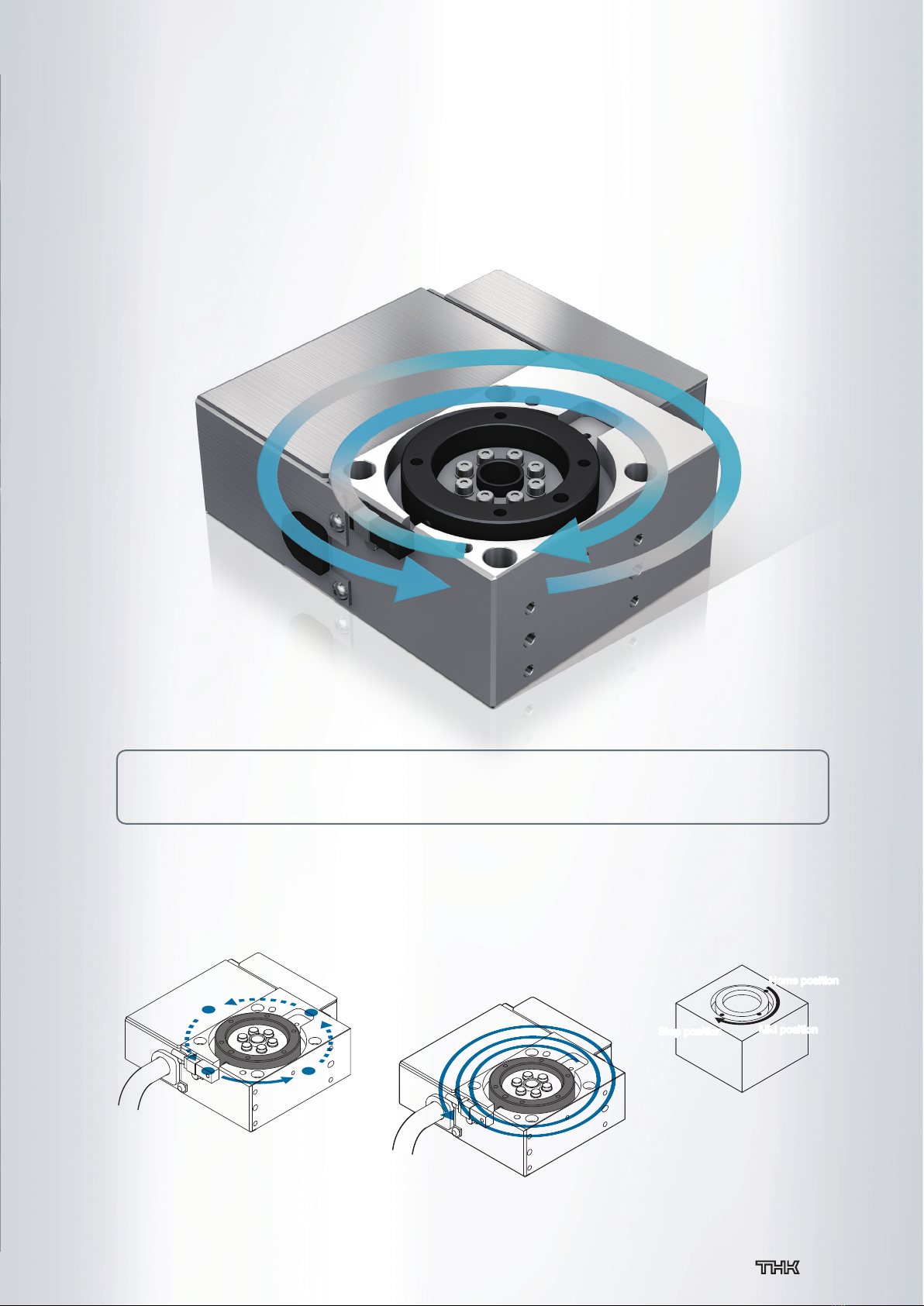
Ample rotary functions only possible
with an electric drive
Consistent movement at
any installation angle
Thin Electric Turntable ET
Multi-point positioning, multi-rotation control
(speed can also be adjusted)
The combination of an electric drive with position control makes it possible to easily set three or more
positions without stoppers.
Capable of multiple movements, including clockwise and counterclockwise rotation control, speed control,
and continuous rotation.
Stop positionStop position Mid position
Mid position
Home position
Home position
Multi-point positioning
Continuous rotation in one direction
Up to three stop positions with pneumatics
1
Ample rotary functions only possible
with an electric drive
Consistent movement at
any installation angle
Thin Electric Turntable ET
Multi-point positioning, multi-rotation control
(speed can also be adjusted)
The combination of an electric drive with position control makes it possible to easily set three or more
positions without stoppers.
Capable of multiple movements, including clockwise and counterclockwise rotation control, speed control,
and continuous rotation.
Stop positionStop position Mid position
Mid position
Home position
Home position
Multi-point positioning
Continuous rotation in one direction
Up to three stop positions with pneumatics
2
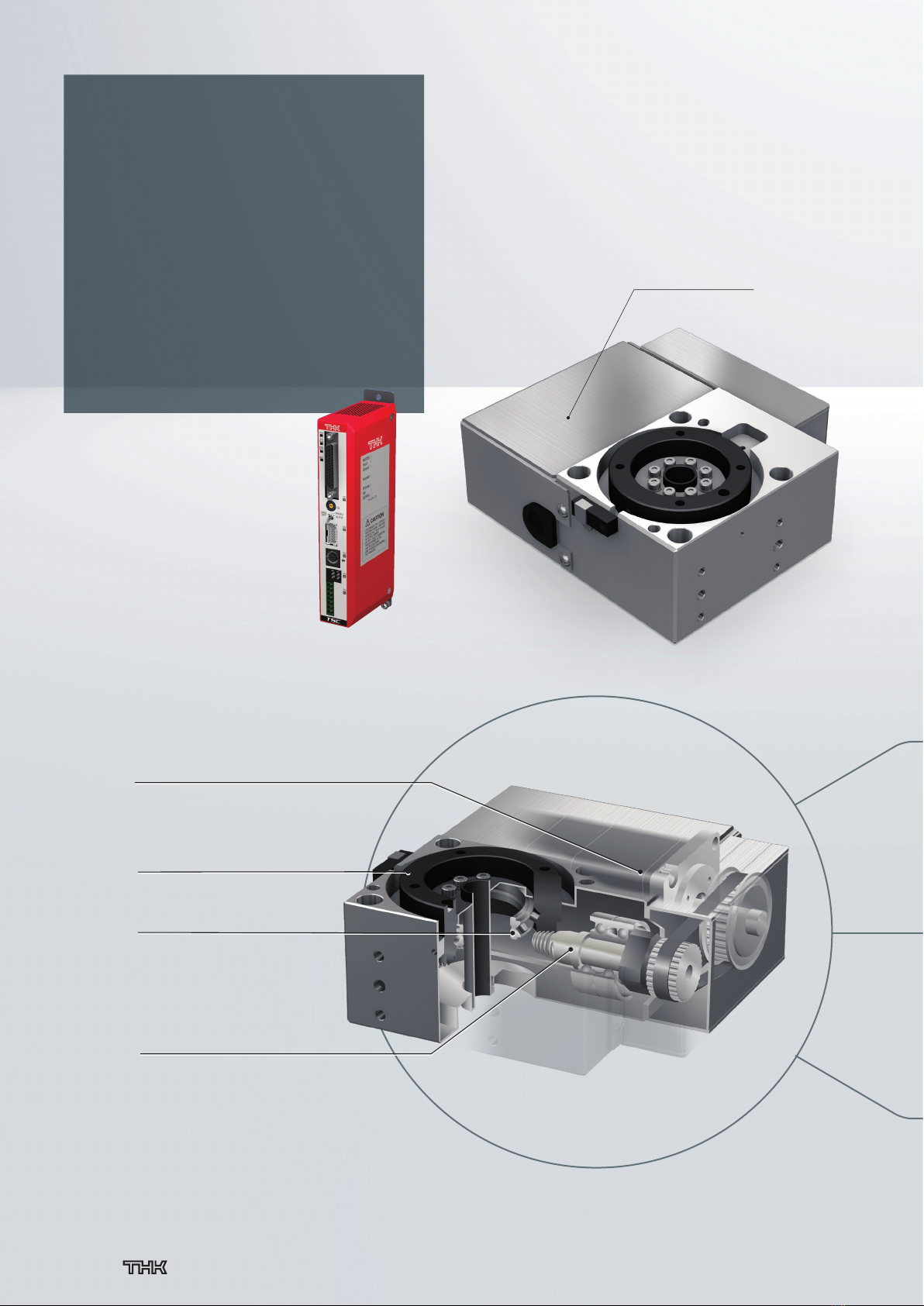
TSC specifications
Without motor
Stepper motor built in
Stepper motor specifications Servo motor specifications
Different varieties are available for purchase
This product can come with a motor that pairs with the THK controller, a motor that you specify, or no
motor installed.
Choose from 330° (mechanical homing type) or 360° (sensor homing type) to match your control application.
High-performance ET structure
A mechanism that achieves high rotational accuracy
The rotary structure combines
a THK cross-roller ring and hypoid gear.
Thin structure
Product height is reduced by providing a compact rotary table
and motor and integrating the cross-roller ring and hypoid gear.
This helps equipment take up less space.
Rotary table (330°, 360°)
Motor
Cross-roller ring
Hypoid gear
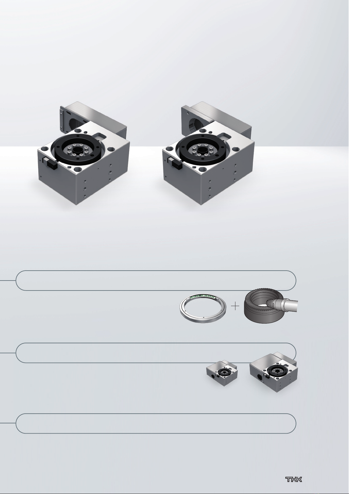
ET20 ET35
Cross-roller ring Hypoid gear
ET
Multi-point positioning
Continuous rotation in one direction
Rotation speed control
Freely set at any angle
Positioning repeatability: ±0.04 degrees
Stepper Driver
Controller TSC
3
TSC specifications
Without motor
Stepper motor built in
Stepper motor specifications Servo motor specifications
Different varieties are available for purchase
This product can come with a motor that pairs with the THK controller, a motor that you specify, or no
motor installed.
Choose from 330° (mechanical homing type) or 360° (sensor homing type) to match your control application.
High-performance ET structure
A mechanism that achieves high rotational accuracy
The rotary structure combines
a THK cross-roller ring and hypoid gear.
Thin structure
Product height is reduced by providing a compact rotary table
and motor and integrating the cross-roller ring and hypoid gear.
This helps equipment take up less space.
Rotary table (330°, 360°)
Motor
Cross-roller ring
Hypoid gear
ET20 ET35
Cross-roller ring Hypoid gear
ET
Multi-point positioning
Continuous rotation in one direction
Rotation speed control
Freely set at any angle
Positioning repeatability: ±0.04 degrees
Stepper Driver
Controller TSC
4
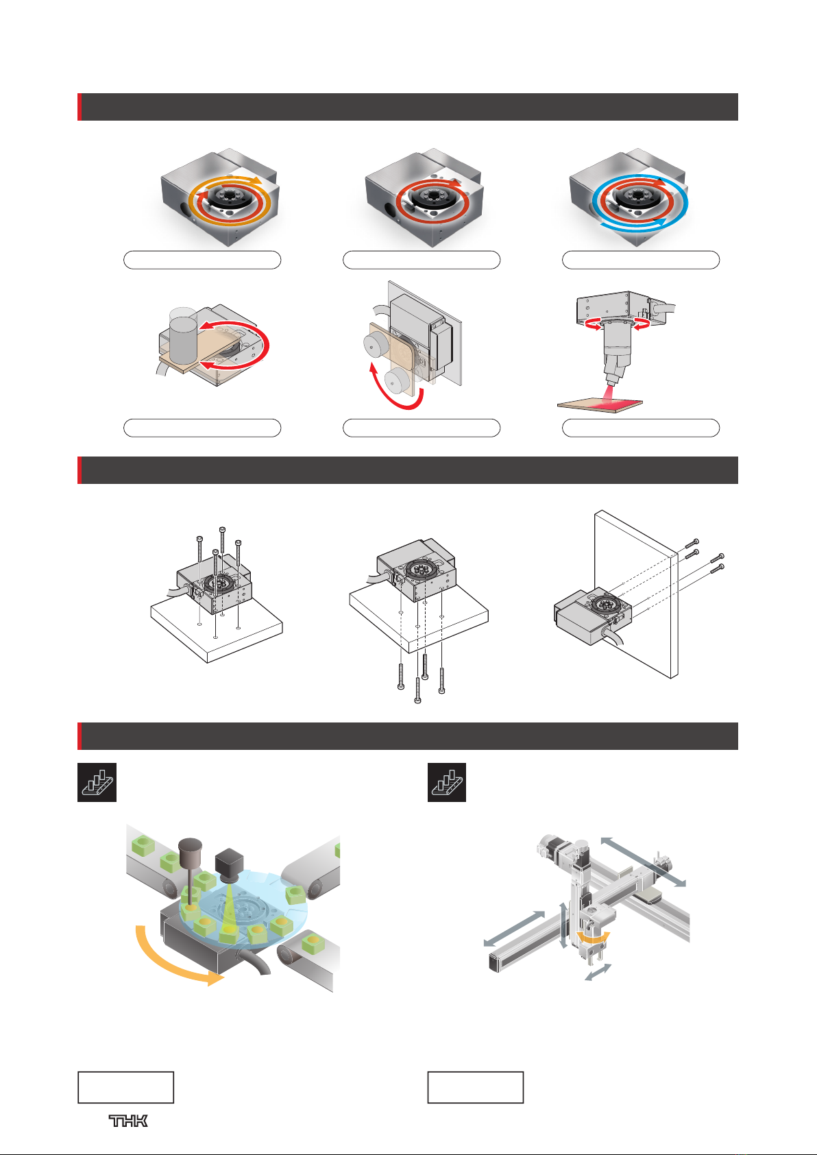
The ET is used in the hand rotary mechanism of the
orthogonal-axis robot. The reduced weight of the thin structure
allows for a decreased load on the lower axis.
The ET is used in the parts that rotate the table. The rotary
mechanism combines a cross-roller ring and a hypoid gear to
achieve highly accurate indexing.
θ
axis: ET
Model used
θ
axis: ET
Hand: EG
X, Y, and Z axis: KSF
Models used
Orthogonal-axis robot
General industry
Index table
General industry
Diversified Applications
Basic Applications (Rotation)
330°/360° stroke rotation
Continuous rotation in one direction
Clockwise/counterclockwise rotation
Applied moment
No speed fluctuations from varying loads
Suspended installation
This product can be mounted from any surface, making it easy to install anywhere.
Note) This product cannot be installed with the
pulley facing downward. See the instruction
manual for details.
Upper surface
installation
Lower surface
installation
Side surface
installation
Two sizes are available: ET20 and ET35. The reduction ratio and motor size for each are given below.
Without motor: Servo motor specifications
TSC specifications
Without motor: Stepper motor specifications
Reduction ratio 45: 1/45
ET20
Reduction ratio 20: 1/20 30: 1/30
ET35
Reduction ratio 45: 1/45
ET20
Reduction ratio 20: 1/20 30: 1/30
ET35
Reduction ratio 45: 1/45
ET20
Reduction ratio
Motor size: 40×40
Motor size: 35×35
Motor size: 40×40
Motor size: 35×35
Motor size: 25×25
Motor size: 40×40
20: 1/20 30: 1/30
ET35
ETET
KSFKSF
KSFKSF
EGEG
KSFKSF
ETET
Applications
Mounting Methods
Example Applications
5

The ET is used in the hand rotary mechanism of the
orthogonal-axis robot. The reduced weight of the thin structure
allows for a decreased load on the lower axis.
The ET is used in the parts that rotate the table. The rotary
mechanism combines a cross-roller ring and a hypoid gear to
achieve highly accurate indexing.
θ
axis: ET
Model used
θ
axis: ET
Hand: EG
X, Y, and Z axis: KSF
Models used
Orthogonal-axis robot
General industry
Index table
General industry
Diversified Applications
Basic Applications (Rotation)
330°/360° stroke rotation
Continuous rotation in one direction
Clockwise/counterclockwise rotation
Applied moment
No speed fluctuations from varying loads
Suspended installation
This product can be mounted from any surface, making it easy to install anywhere.
Note) This product cannot be installed with the
pulley facing downward. See the instruction
manual for details.
Upper surface
installation
Lower surface
installation
Side surface
installation
Two sizes are available: ET20 and ET35. The reduction ratio and motor size for each are given below.
Without motor: Servo motor specifications
TSC specifications
Without motor: Stepper motor specifications
Reduction ratio 45: 1/45
ET20
Reduction ratio 20: 1/20 30: 1/30
ET35
Reduction ratio 45: 1/45
ET20
Reduction ratio 20: 1/20 30: 1/30
ET35
Reduction ratio 45: 1/45
ET20
Reduction ratio
Motor size: 40×40
Motor size: 35×35
Motor size: 40×40
Motor size: 35×35
Motor size: 25×25
Motor size: 40×40
20: 1/20 30: 1/30
ET35
General Specifications
6
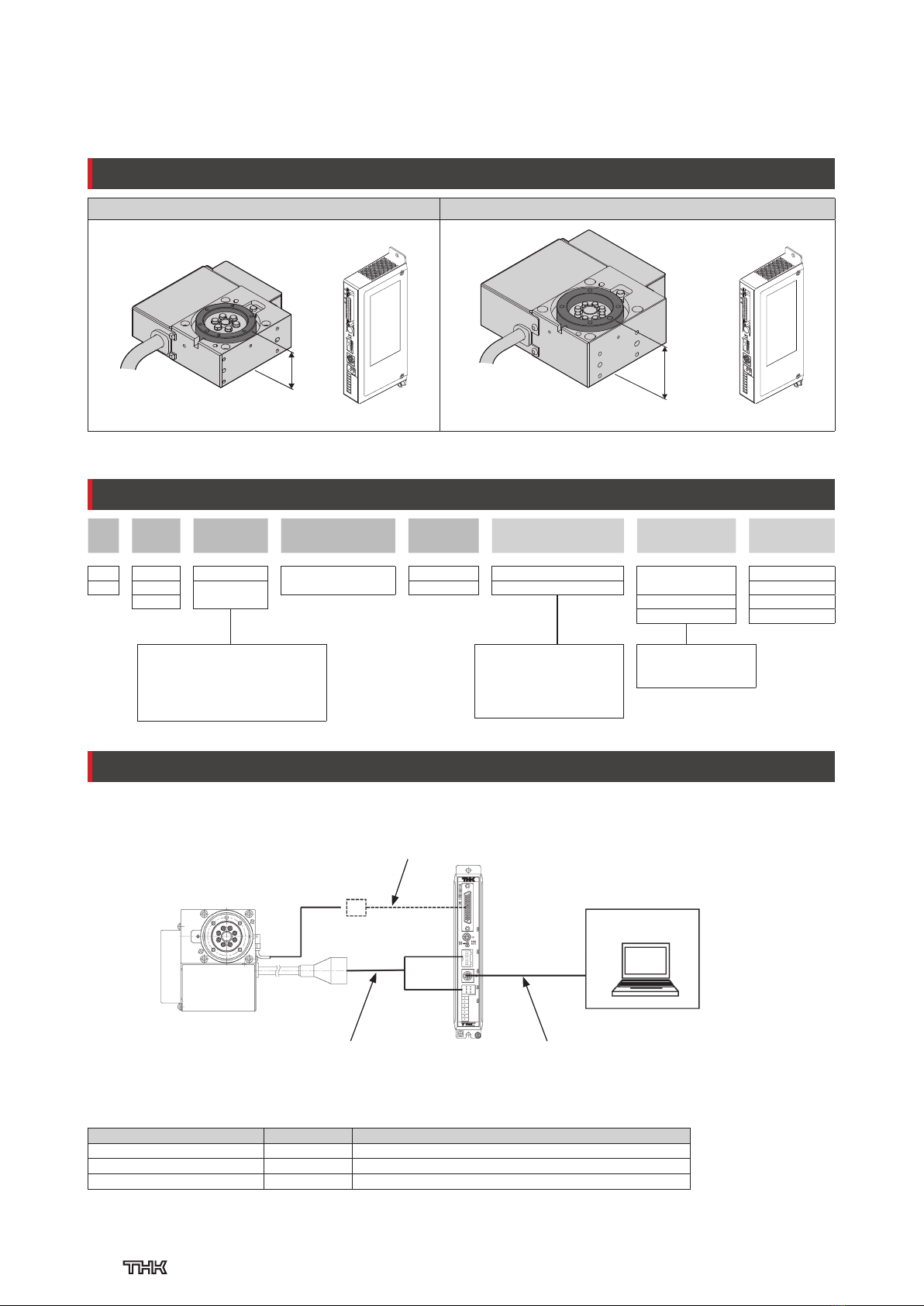
Lineup
ET20+TSC ET35+TSC
301
+
441
+
Users can select a reduction ratio.
1This dimension represents the distance from the bottom surface of the base to the top surface of the table.
ET (with Stepper Driver Controller TSC)
Combination with dedicated driver controller
Model Number Coding
The available motor options
vary based on the model.
ET20: 20P
ET35: 35P
D00 and R00 use
mechanical homing.
Model
Reduction ratio
Stroke Control device Options Motor size Home position Cable length
① ② ③ ④ ⑤ ⑥ ⑦ ⑧
ET20 — 45 — 330 — TS — / 20P — D00 — S3
ET20 20: 1/20 330: 330° TS: Stepper Driver
Controller TSC
No symbol
: None
20P: Stepper motor 20×20 No symbol:
Multi-rotation
specifications
No symbol: None
ET35 30: 1/30 360:
Multi-rotation
specifications
2
U: Sensor 35P: Stepper motor 35×35 S3: Standard 3 m
45: 1/45 D00:
Counter-clockwise movement
S5: Standard 5 m
R00:
Clockwise movement
SA: Standard 10 m
System Configuration
The customer must supply the wiring.
PC set-up software
D-step
Actuator cable (included)
CBL-TSC-AC-**-B
PC communication cable (sold separately)
CBL–COM–03
CN1
CN2
CN3
CN4
The system configuration is as follows when “360: Multirotation specifications” is selected.
Magnetic proximity switch: AH003 (ASA ELECTRONICS INDUSTRY CO., LTD.)
・Cable ends: multi-conductor cable
・Cable length: Longer than 1 m
(length of covered portion of the cable
from the switch end)
Note) When using a 10 m actuator cable, please insert a noise filter in the TSC power source.
We recommend the RSAN-2003 noise filter from the TDK-Lambda Corporation.
Cable List
Cable Quantity Notes
Actuator cable for TSC 1 Comes with compatible actuator
I/O cable 1 Sold separately (I/O connector for TSC side only comes with TSC)
PC communication cable 1 Sold separately
2There are conditions for using the
product under TSC specifications
in continuous rotation in one
direction. Please contact THK for
more information.
Controller must be procured
separately.
→p. 20
7
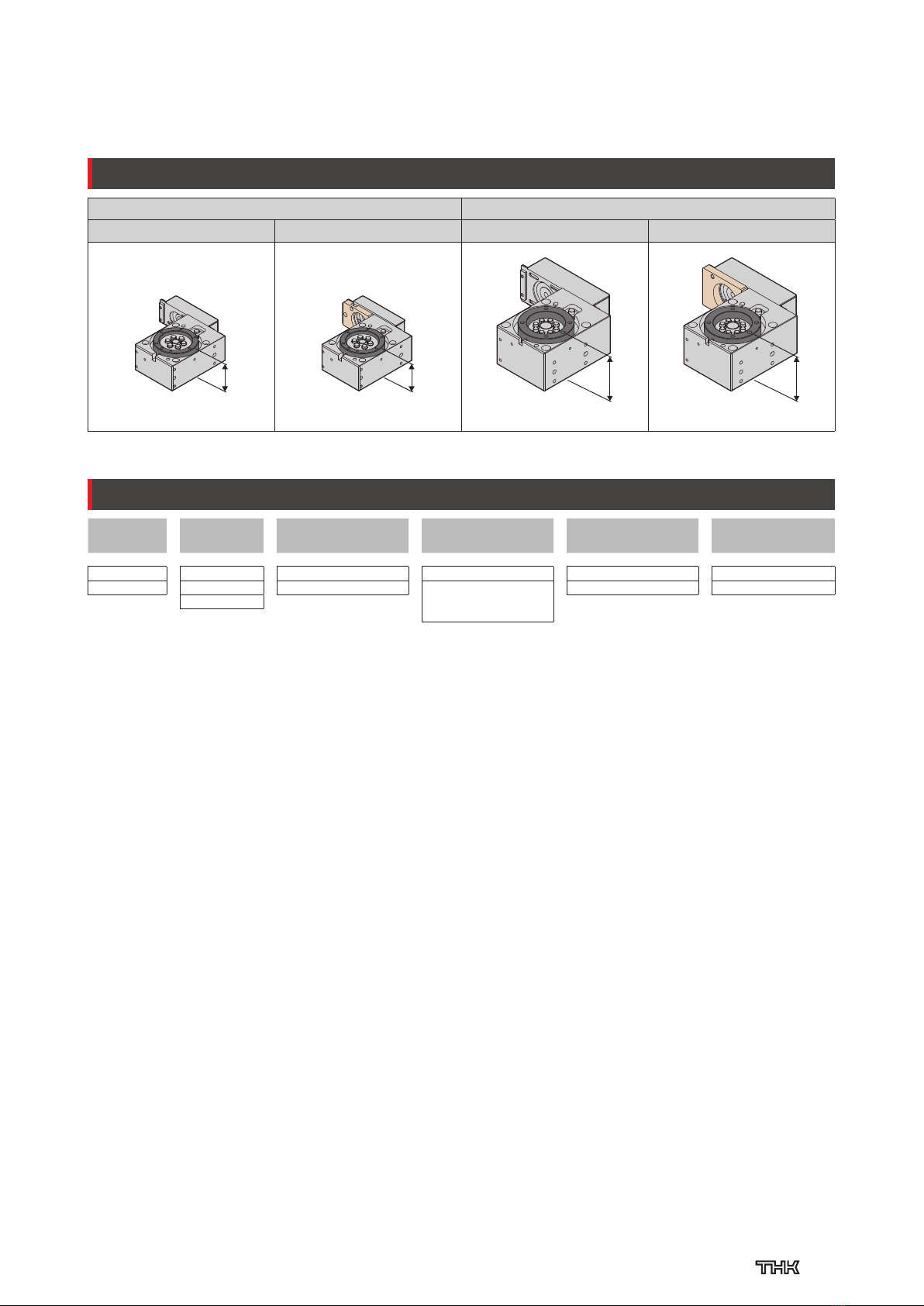
ET (Without Motor)
Main actuator unit only or equipped with motor specified by customer
Lineup
ET20 ET35
Stepper motor specifications Servo motor specifications Stepper motor specifications Servo motor specifications
30
30
44
44
Users can select a
reduction ratio.
Users can select a
reduction ratio.
Model Number Coding
Model
Reduction ratio
Stroke With/without motor Motor bracket Options
① ② ③ ④ ⑤ ⑥
ET20 — 45 — 360 — 0 — A — U
ET20 20: 1/20 330: 330° 0: Without motor A: Stepper motor No symbol: None
ET35 30: 1/30 360:
Multi-rotation specifications
1:
With motor (THK will purchase
and mount the motor you
specify)
B: Servo motor U: Sensor
45: 1/45
8

ET20
Controller Specification
Basic Specifications
Model Number Coding
Selection Information
Motor
wrap
Body height
30 mm
Stepper
motor
20×20
Turn
table
type
Servo motor
30 W
Servo motor
20 W
If "TS" is selected for ④With or without motor/controller type,
selections must be made for ⑦to ⑨.
Model
Reduction
ratio
Stroke With or without motor/
controller type
Motor
bracket Sensor Motor size Home position Cable length
① ② ③ ④ ⑤ ⑥ ⑦ ⑧ ⑨
ET20 — 45 — 360 — 0 — A — U / 20P — D00 — S3
ET20 45:
1/45
330: 330° TS: Stepper Driver
Controller TSC
No symbol: None
No symbol: None
20P:
Stepper motor
20×20
No symbol
: Multi-rotation
specifications
No symbol
: None
360:
Multi-rotation
specifications
1
A:
Stepper motor type
U: Sensor S3:
Standard 3 m
0: Without motor
D00
:
Counter-clockwise movement
S5:
Standard 5 m
1: With motor
(THK will purchase
and mount the
motor you specify)
B:
Servo motor type
R00
:
Clockwise movement
SA:
Standard 10 m
2Varies based on angular velocity. See p. 10 "Angular Velocity versus Output Torque" graph for
details.
Motor size 20×20
Stroke (one side) (°) 330 or 360
Drive system Hypoid gear
Output shaft bearing Cross-roller ring
Reduction ratio 1/45
Max. permissible load torque (N·m) 0.3
Max. permissible moment of inertia (kg·m2) 0.0057
Max. angular velocity (°/s) 270
Max. angular acceleration (°/s) 2000
Positioning repeatability (°) ±0.04
Backlash3(°) 0.2
Permissible axial load4, 5 (N) 30
Permissible radial load4, 5 (N) 13.2
Permissible moment4, 5 (N·m) 3.6
Permissible input torque (N·m) 0.039
Mass6(kg) 0.52 (0.35)
3Depending on usage conditions, minor wear to the hypoid gear may cause increased
backlash.
4Please use with a safety margin of 1.5 or greater.
5This is the permissible value when loaded in one direction.
6Values in parentheses are for no motor specifications.
Control device TSC
Motor size 20×20
Reduction ratio 1/45
Max. output torque2(N·m) 0.3
Max. permissible moment of inertia (kg·m2) 0.0057
Permissible Load and Permissible Moment
Axial
Moment
Moment
Radial
1There are conditions for
using the product under
TSC specifications in
continuous rotation in one
direction. Please contact
THK for more information.
The available sensor
options vary based on
the stroke.
330: No Symbol
360: U
360° stroke (multi-rotation)
uses a homing sensor (1 m
cable).
D00 and R00 use mechanical homing.
R00
D00
9

ET20
Angular Velocity versus Permissible Moment of Inertia
Angular Velocity versus Output Torque
Note 1) This graph represents cases where the angular acceleration is 2000°/s2.
Note 2) When the ambient temperature is low (below 10°C), the permissible moment of inertia will decrease in the high angular velocity range.
Note 3) When the ambient temperature is low (below 10°C), the output torque will decrease in the high angular velocity range.
Note 4) Please use a safety margin of 1.5 or higher for the output torque.
Motor Shaft Rotation Speed versus Internal Resistance Torque
0.000
0.001
0.002
0.003
0.004
0.005
0.006
0.007
0 50 100 150 200 250
0.0057
0.0027
0.0007
180
Permissible moment of inertia (kg·m2)
Angular velocity (°/s)
Ambient temperature: 10°C or more
Ambient temperature: Less than 10°C
0.00
0.05
0.10
0.15
0.20
0.25
0.30
0.35
0.40
0 50 100 150 200 250
0.14
0.30
0.03
180
Output torque (N·m)
Angular velocity (°/s)
Ambient temperature: 10°C or more
Ambient temperature: Less than 10°C
Motor Selection Information
Compatible Motors
Note 5) Internal resistance torque increases in low-temperature environments (10°C and below).
Therefore, it is recommended to use a higher safety margin when selecting a product.
0.000
0.005
0.010
0.015
0.020
0.025
0 500 1000 1500 2000
0.016
0.023
0.015
0.008
Internal resistance torque (N·m)
Motor shaft rotation speed (min-1)
Ambient temperature: 10°C or more
Ambient temperature: Less than 10°C
Reduction
ratio
Unit mass (with motor)
(kg)
Unit mass (without motor)
(kg)
Moving part mass
(kg)
Unit inertia
(kg·cm2)Efficiency Timing pulley Timing belt
1/45 0.52 0.35 0.07 0.004 0.47 P26-1.5GT-3-33F
(Manufactured by Gates Unitta Asia Company)
100.5-1.5GT-3
(Manufactured by Gates Unitta Asia Company)
AC servo motor
Motor rated
output (W)
Flange size Motor
bracket
YASKAWA Electric
Corporation
Σ
-Vmini SGMMV–A2 20 25×25 B
SGMMV–A3 30
Mitsubishi Electric
Corporation
MELSERVO J4 HG–AK0236 20 25×25 B
HG–AK0336 30
Stepper motor
Flange size Motor
bracket
ORIENTAL MOTOR CO., LTD.
2-phase PKP214D06* 20×20 A
Note 6) Please select and use a motor that is suited to the usage conditions. The table
shows only a portion of the model numbers for motors. For details regarding model
numbers, please see the catalog for each respective motor manufacturer.
Note 7) If the maximum torque of the installed motor will exceed the permissible input
torque (p. 9), please consider a safety measure to limit the torque.
Note 8) Please select a D-cut type motor output shaft.
Note 9) Installation may not be possible depending on the motor options, so please verify in
advance.
10
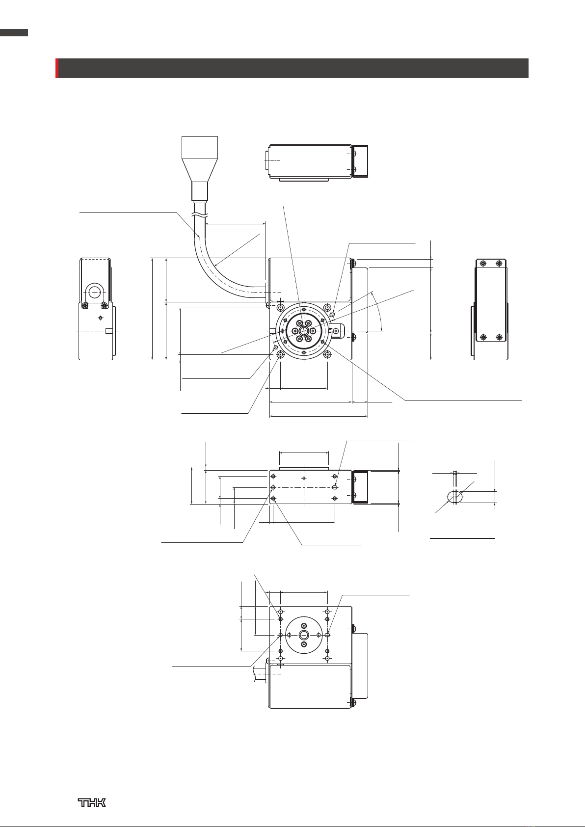
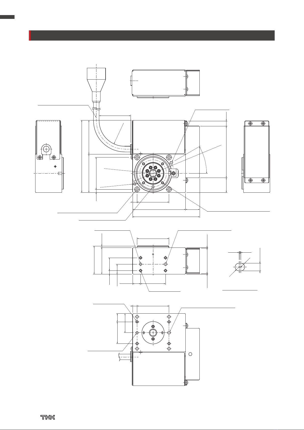
ET20
Elongated hole
details
50 mm or more
(83)
47 (36)
(4.5) 38
(22) (53) (7)
(80)
67 (13)
9 38
φ
40 -0.005
-0.025
(0.7) (26) (0.8)
30
27.5 (2.5)
4.5 18
13.5
3 50
4-M3 depth 6
Elongated hole
depth 2.5
10.526
23.5
9 38
0.5 0.5
3+0.03
0
(R)
30°
Elongated hole
depth 2.5
PCD 53
Elongated hole
depth 2.5
φ
3+0.02
0 depth 2.5
4-3.4 through,
φ
6 counterbore,
depth 3.5
φ
3+0.02
0 depth 2.5
φ
2.5H8
depth 2.5
4-M3 depth 5
φ
3+0.02
0 depth 2.5
6-M2.5 depth 4
PCD 35 (spaced every 60°)
0
+0.014
R40 or more
φ
6 through
Cable length: 332 mm
(R)
TSC Specifications
Dimensions
11

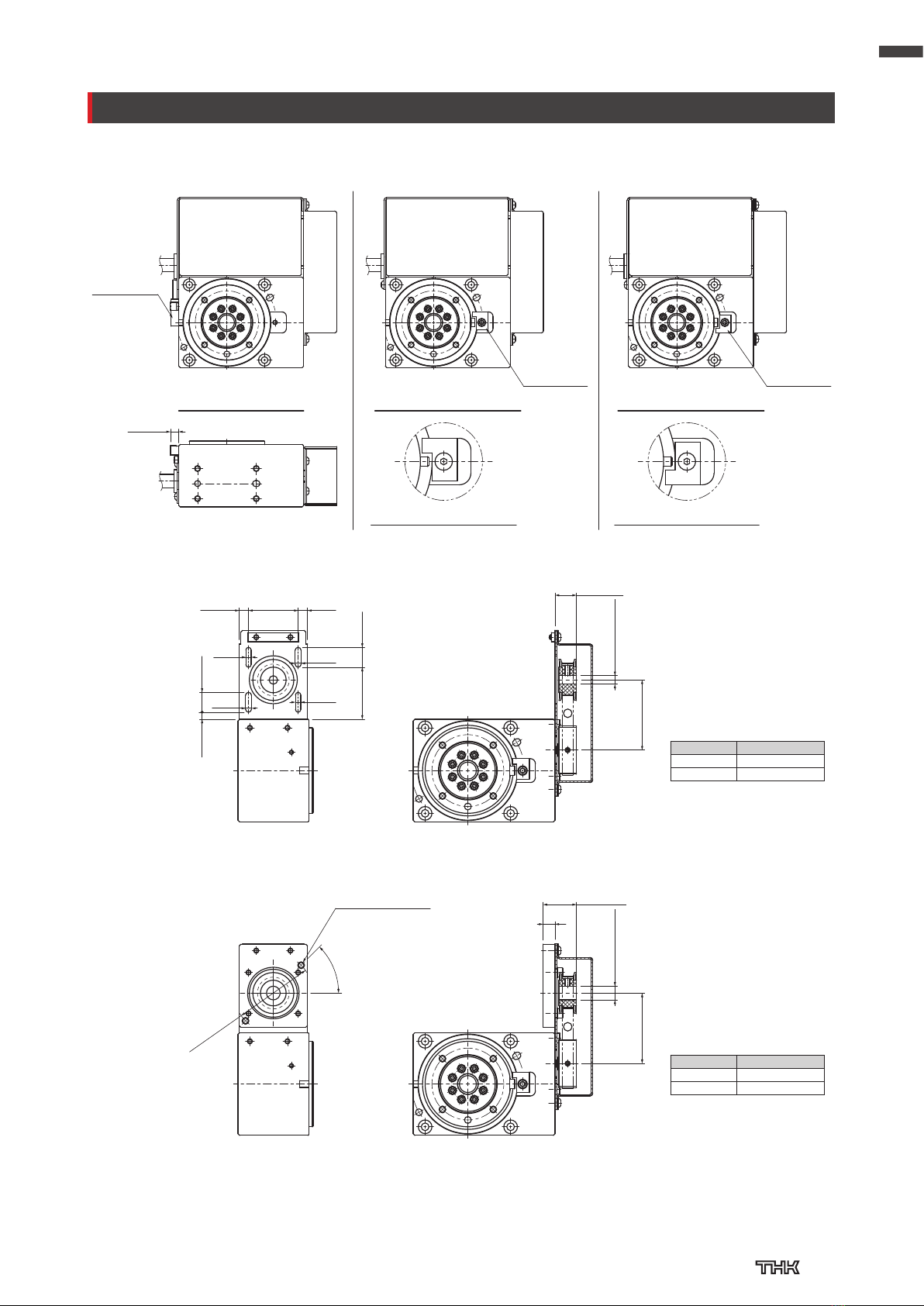
ET20
16
2.2
(5) 5
4.73.7
2.6
(10.5)
(25.7)
(Between shafts)
19.6 6.1
φ
4H7
φ
5H7 +0.012
0
2-3.4 drill through
45°
PCD 28
(25.3)
(Between shafts)
(16)
5.5
+0.012
0
330° specifications (D00)
Stopper details (D00)
Home
position
stopper
330° specifications (R00)
Stopper details (R00)
Home
position
stopper
360° specifications
Home
position
sensor
(5.5)
Homing Specifications
Without Motor (Stepper Motor Specifications)
Without Motor (Servo Motor Specifications)
Note) The homing stopper is for detecting the home
position. If a stopper is necessary to prevent
overrun, please prepare one separately.
Note) The homing stopper is for detecting the home
position. If a stopper is necessary to prevent
overrun, please prepare one separately.
Dimensions
12

ET35
Controller Specifications
Basic Specifications
Model Number Coding
Selection Information
Body height
44 mm
Servo motor
100 W
Motor
wrap
Stepper
motor
35×35
Turn
table
type
Servo motor
80 W
Servo motor
50 W
If "TS" is selected for ④With or without motor/controller type,
selections must be made for ⑦to ⑨.
Model
Reduction
ratio
Stroke With or without motor/
controller type
Motor
bracket Sensor Motor size Home position Cable length
① ② ③ ④ ⑤ ⑥ ⑦ ⑧ ⑨
ET35 — 20 — 360 — TS — — U / 35P — D00 — S3
ET35 20:
1/20
330: 330° TS: Stepper Driver
Controller TSC
No symbol: None
No symbol: None
35P:
Stepper motor
35×35
No symbol
: Multi-rotation
specifications
No symbol
: None
30:
1/30
360:
Multi-rotation
specifications
1
A:
Stepper motor type
U: Sensor S3:
Standard 3 m
0: Without motor
D00
:
Counter-clockwise movement
S5:
Standard 5 m
1: With motor
(THK will purchase
and mount the
motor you specify)
B:
Servo motor type
R00
:
Clockwise movement
SA:
Standard 10 m
Motor size 35×35
Stroke (one side) (°) 330 or 360
Drive system Hypoid gear
Output shaft bearing Cross-roller ring
Reduction ratio 1/20 1/30
Max. permissible load torque (N·m) 2.2 3.3
Max. permissible moment of inertia (kg·m2) 0.028 0.042
Max. angular velocity (°/s) 600 400
Max. angular acceleration (°/s) 3000
Positioning repeatability (°) ±0.04
Backlash3(°) 0.2
Permissible axial load4, 5 (N) 200
Permissible radial load4, 5 (N) 88
Permissible moment4, 5 (N·m) 17.7
Permissible input torque (N·m) 0.248
Mass6(kg) 1.2 (0.8)
3Depending on usage conditions, minor wear to the hypoid gear may cause increased
backlash.
4Please use with a safety margin of 1.5 or greater.
5This is the permissible value when loaded in one direction.
6Values in parentheses are for no motor specifications.
The available sensor
options vary based on
the stroke.
330: No Symbol
360: U
360° stroke (multi-rotation)
uses a homing sensor (1 m
cable).
D00 and R00 use mechanical homing.
R00
D00
Permissible Load and Permissible Moment
Axial
Moment
Moment
Radial
Control device TSC
Motor size 35×35
Reduction ratio 1/20 1/30
Max. output torque2(N·m) 2.2 3.3
Max. permissible moment of inertia (kg·m2) 0.028 0.042
2Varies based on angular velocity. See p. 14 "Angular Velocity versus Output Torque" graph for
details.
1There are conditions for
using the product under
TSC specifications in
continuous rotation in one
direction. Please contact
THK for more information.
13

ET35
Motor Selection Information
Compatible Motors
Angular Velocity versus Permissible Moment of Inertia
Angular Velocity versus Output Torque
Output torque (N·m)
Angular velocity (°/s)
0
.0
0
.5
1
.0
1
.5
2
.0
2
.5
3
.0
3
.5
4.0
0 100 200 300 400 500 600
3.3
0.9
2.2
0
.6
0.4
0.6
133
ET35–30 (Ambient temperature: 10°C or more)
ET35–30 (Ambient temperature: Less than 10°C)
ET35–20 (Ambient temperature: 10°C or more)
ET35–20 (Ambient temperature: Less than 10°C)
Motor Shaft Rotation Speed versus Internal Resistance Torque
Note 3) Internal resistance torque increases in low-temperature environments (10°C and below).
Therefore, it is recommended to use a higher safety margin when selecting a product.
0.000
0.010
0.020
0.030
0.040
0.050
0.060
0.070
0.080
0.090
0 500 1000 1500 2000
0.045
0.077
0.056
0.032
0.053
0.037
0.016
0.024
Internal resistance torque (N·m)
Motor shaft rotation speed (min-1)
ET35–30 (Ambient temperature: 10°C or more)
ET35–30 (Ambient temperature: Less than 10°C)
ET35–20 (Ambient temperature: 10°C or more)
ET35–20 (Ambient temperature: Less than 10°C)
Note 1) This graph represents cases where the angular acceleration is 3000°/s2.
Note 2) Please use a safety margin of 1.5 or higher for the output torque.
Permissible moment of inertia (kg·m2)
Angular velocity (°/s)
0
.000
0
.005
0
.010
0
.015
0
.020
0
.025
0
.030
0
.035
0
.040
0
.045
0.050
0 100 200 300 400 500 600
0.042
0.028
0.011 0
.007
0.007
0
.005
133
ET35–30 (Ambient temperature: 10°C or more)
ET35–30 (Ambient temperature: Less than 10°C)
ET35–20 (Ambient temperature: 10°C or more)
ET35–20 (Ambient temperature: Less than 10°C)
Reduction
ratio
Unit mass (with motor)
(kg)
Unit mass (without motor)
(kg)
Moving part mass
(kg)
Unit inertia
(kg·cm2)Efficiency Timing pulley Timing belt
1/20 1.2 0.8 0.17 0.012 0.72
P26-2GT-6-33F
(Manufactured by Gates Unitta Asia Company)
134-2GT-6
(Manufactured by Gates Unitta Asia Company)
1/30 1.2 0.8 0.17 0.015 0.71
P26-2GT-6-33F
(Manufactured by Gates Unitta Asia Company)
148-2GT-6
(Manufactured by Gates Unitta Asia Company)
AC servo motor
Motor rated
output (W)
Flange size Motor
bracket
YASKAWA
Electric
Corporation
Σ
-V
SGMJV–A5 50
40×40 B
SGMJV-01 100
SGMAV–A5 50
SGMAV-01 100
Σ
–7
SGM7J–A5 50
40×40 B
SGM7J-01 100
SGM7A–A5 50
SGM7A-01 100
Σ
-X
SGMXJ–A5 50
40×40 B
SGMXJ-01 100
SGMXA–A5 50
SGMXA-01 100
Mitsubishi
Electric
Corporation
MELSERVO
J4
HG–KR053 50
40×40 B
HG-KR13 100
HG–MR053 50
HG-MR13 100
J5 HK–KT053W 50 40×40 B
HK-KT13W 100
AC servo motor
Motor rated
output (W)
Flange size Motor
bracket
TAMAGAWA
SEIKI CO.,
LTD.
TBL-i
ⅡTS4602 50 40 × 40 B
TS4603 100
TBL-iⅣTSM3102 50 40×40 B
TSM3104 100
SANYO DENKI
CO., LTD. SANMOTION R
R2*A04005 50
40×40 BR2EA04008 80
R2AA04010 100
Stepper motor
Flange size Motor
bracket
ORIENTAL MOTOR CO., LTD.
2-phase PKP235* 35×35 A
Note 4) Please select and use a motor that is suited to the usage conditions. The table
shows only a portion of the model numbers for motors. For details regarding model
numbers, please see the catalog for each respective motor manufacturer.
Note 5) If the maximum torque of the installed motor will exceed the permissible input
torque (p. 13), please consider a safety measure to limit the torque.
Note 6) Please select a D-cut type motor output shaft.
Note 7) Installation may not be possible depending on the motor options, so please verify in
advance.
14
ET35
Elongated hole
details
φ
10 through
(113)
60 (53)
(5) 50
(23) (81) (8)
(105)
83 (22)
7 50
50 mm or more
PCD 66
-0.005
-0.025
44
41.5 (2.5)
5.5 20
15.5
12.5 39
(0.7) (40) (0.8)
7 50
1334
30
+0.03
0 depth 3
4-M4 depth 8
+0.03
0 depth 3
Elongated hole depth 3
Elongated hole
depth 3
Elongated hole depth 3
0.5 0.5
4+0.03
0
(R)
30°
4-M4 depth 8
φ
4+0.03
0 depth 3
4-
φ
4.5 through,
φ
8 counterbore, depth 9.5
φ
4H8
φ
4
φ
4
φ
50
+0.018
0 depth 4
4-M4 depth 7
PCD 42 (spaced every 90°)
R40 or more
Cable length: 332 mm
(R)
TSC Specifications
Dimensions
15
ET35
(5.5) 5.529
3.4
3.1
(12.5)
3.4 3.1
30.45 11.6
4.15 11.6
(Between shafts)
φ
5H7 +0.012
0
φ
8H7 +0.015
0
45°
2-M4 depth 7
PCD 46
(19.5)
(Between shafts)
7
Home
position
sensor
(5.5)
360° specifications
Stopper details (D00)
Home
position
stopper
330° specifications (D00)
Stopper details (R00)
Home
position
stopper
330° specifications (R00)
Note) The homing stopper is for detecting the home
position. If a stopper is necessary to prevent
overrun, please prepare one separately.
Note) The homing stopper is for detecting the home
position. If a stopper is necessary to prevent
overrun, please prepare one separately.
Dimensions
Homing Specifications
Without Motor (Stepper Motor Specifications)
Without Motor (Servo Motor Specifications)
Reduction ratio (Between shafts)
1/20 41
1/30 41.3
Reduction ratio (Between shafts)
1/20 41
1/30 41.3
16
Technical Materials
Selection Method
●Calculating the moment of inertia
Confirm whether or not the calculated moment of inertia satisfies the requirements for the permissible moment of inertia
for the model.
If the calculated moment of inertia is less than the permissible moment of inertia, the product may be used.
If the calculated moment of inertia is greater than or equal to the permissible moment of inertia, the product may not be used.
Please select a different model or reduce the mass or rotational radius.
For the permissible moment of inertia for each model, please consult the "Angular Velocity versus Permissible Moment of
Inertia" graph.
Confirm whether or not the calculated torque satisfies the requirements for the maximum output torque for the model.
If the calculated torque is less than the maximum output torque, the product can be used.
If the calculated torque is greater than or equal to the maximum output torque, the product cannot be used.
Please select a different model or reduce the mass or rotational radius.
For the maximum output torque for each model, please consult the "Angular Velocity versus Output Torque" graph.
When selecting a rotary shaft, calculate the moment of inertia and load torque for the usage conditions and make a selection
where the permissible moment of inertia and maximum output torque will not be exceeded.
Refer to the formula below as a representative example and calculate the moment of inertia for the workpiece and mounting
jigs you will be using.
Table
Diameter:
D (m) Height:
L (m)
Mass:
m (kg)
Workpiece
Diameter:
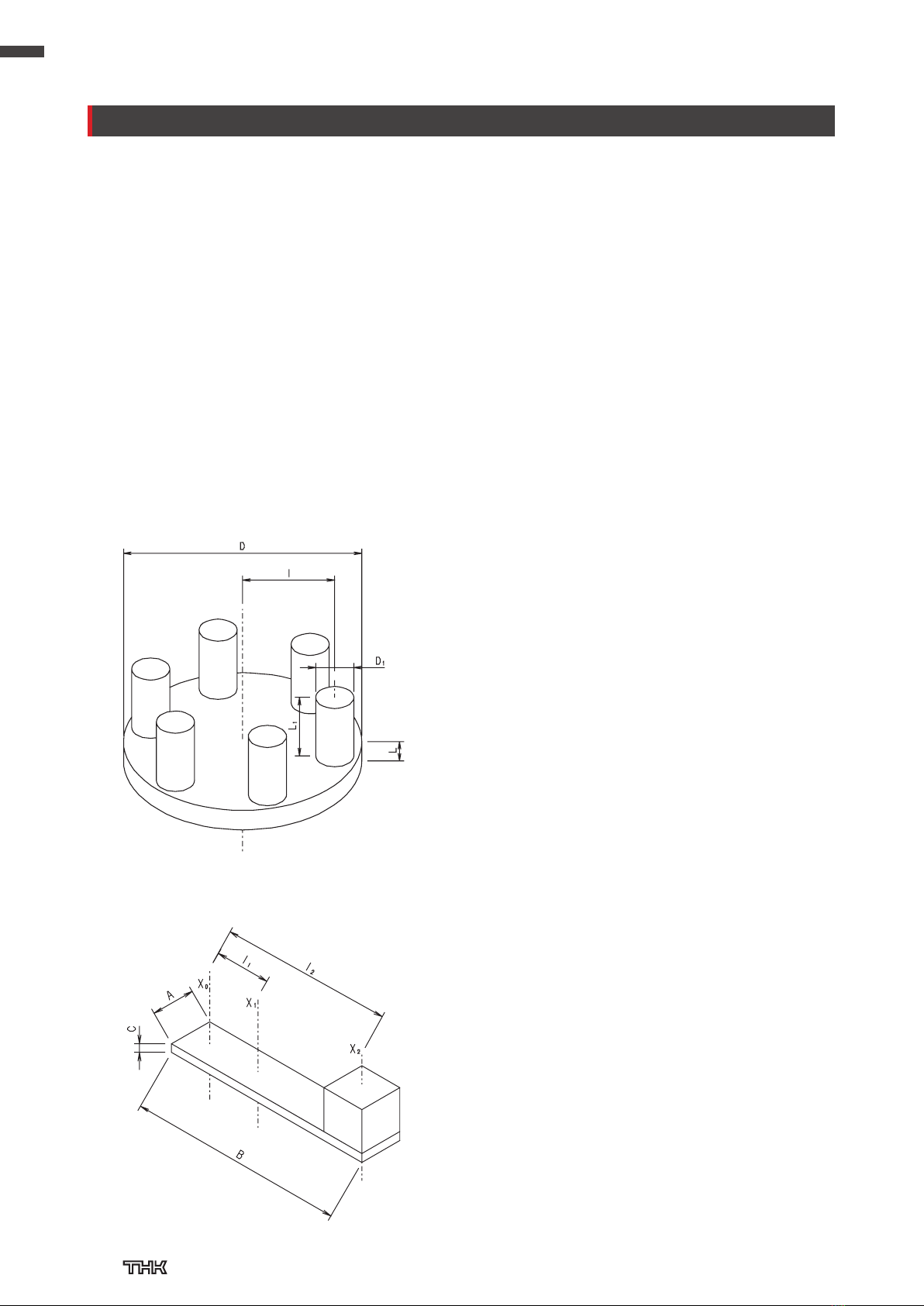
D1(m) Height:
L1(m)
Mass:
m1(kg) Quantity: n (pieces)
Density: ρ (kg/m3)
(Notes)
・
All workpieces are considered to be of the same shape and mass.
・All workpieces are considered to be at the same distance from the
center point.
(Reference) Moment of Inertia for Multiple Rectangular Solids Combined
Rectangular solid:
Depth A (m), height B (m), width C (m), mass m1(kg)
Cube:
Depth A (m), height A (m), width A (m), mass m2(kg)
Density: ρ (kg/m3)
(Reference) Moment of Inertia for Multiple Cylindrical Columns Combined
Ix
1
–
8m·D2
1
–
8n·m·(D12+8l2)
=
m
m1
π
–
4ρ·L·D2
:
π
–
4ρ·L1·D12
:
+[k
g
·m2]
m2(2·A2 + 12·l2
2)
Ix
1
–
12 m1(A2 + B2 + 12·l1
2)
1
–
12
+
=
:
:
:
:
ρ·A·B·C
ρ·A3
Distance between X0and X1(center of rotation X0) (m)
m1
m2
l1
l2
Distance between X0and X2(center of rotation X0) (m)
[kg·m2]
Selection Procedure
17
Technical Materials
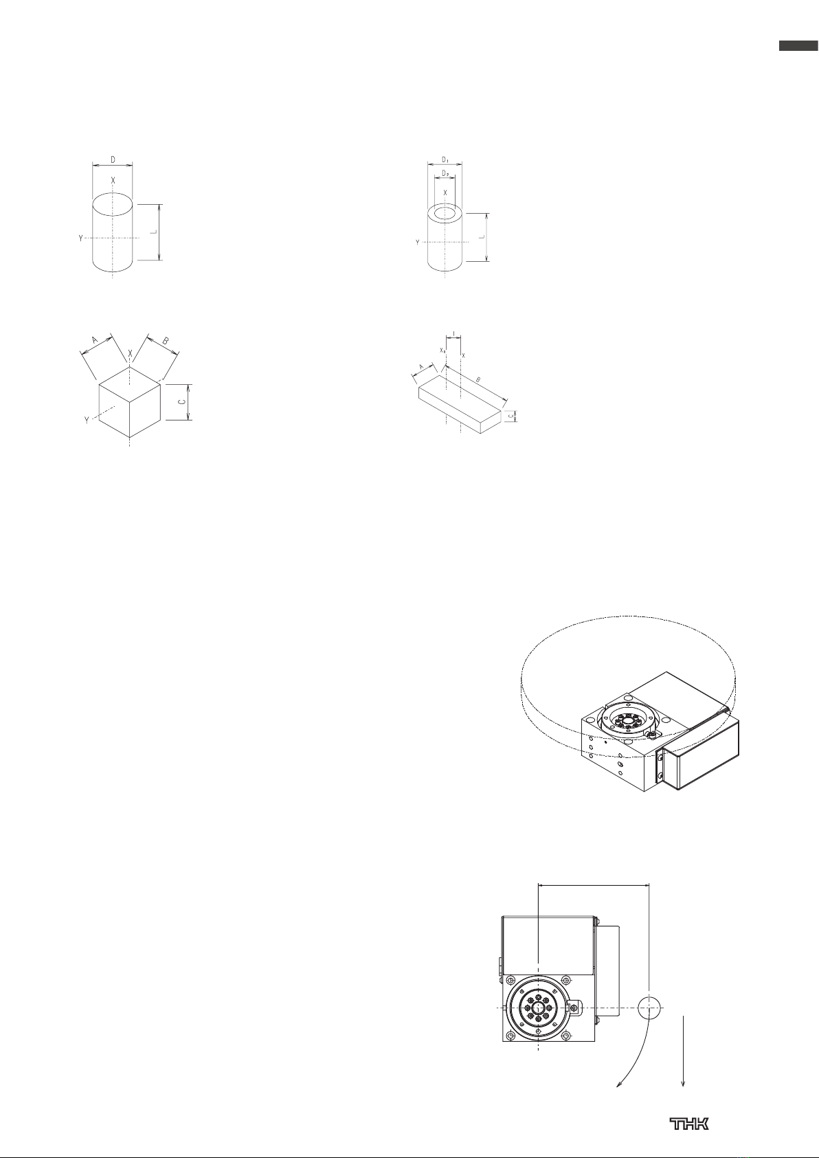
Moment of Inertia for a Cylinder
Moment of Inertia for a Rectangular Solid
Calculating Torque in Horizontal Applications (Installed from the Bottom Surface)
Moment of Inertia for a Hollow Cylinder
Moment of Inertia for an Object with Different Centers of Rotation and Gravity
Outer diameter: D (m)
Length: L (m)
Mass: m (kg)
Density: ρ (kg/m3)
Outer diameter: D1(m)
Inner diameter: D2
Length: L (m)
Mass: m (kg)
Density: ρ (kg/m3)
Depth: A (m) Width:
B (m)
Height: C (m) Mass:
m (kg)
Density: ρ (kg/m3)If Iis less than the permissible moment of inertia, the product can
be used.
If Iis greater than or equal to the permissible moment of inertia, the
product cannot be used. Please select a different model or reduce
the mass or rotational radius.
For the permissible moment of inertia for each model, please consult
the "Angular Velocity versus Permissible Moment of Inertia" graph.
I: Moment of inertia (kg·m2)
ω ′ : Angular acceleration (rad/s2)
Please ensure a safety margin of 1.5 or greater.
Example) External torque (friction torque)
External torque = μ
・
m
・
g
・
r
m: Workpiece mass (kg) g: Gravitational acceleration (m/s2)
μ: Friction coefficient ET20: 0.020 r: Rotary table radius ET20: 29 (mm)
ET35: 0.017 ET25: 34 (mm)
Confirm whether or not the calculated torque satisfies the requirements for the maximum
output torque for the model.
If T1is less than the maximum output torque, the product can be used.
If T1is greater than or equal to the maximum output torque, the product cannot be used.
Please select a different model or reduce the mass or rotational radius.
For the maximum output torque for each model, please consult the "Angular Velocity
versus Output Torque" graph.
Calculating Torque in Horizontal Applications (Installed from a Side Surface)
m: Workpiece mass (kg)
g: Gravitational acceleration (m/s2)
r: Radius (m) I: Moment of inertia (kg·m2)
ω ′ : Angular acceleration (rad/s2)
Please ensure a safety margin of 1.5 or greater.
Confirm whether or not the calculated torque satisfies the requirements for the
maximum output torque for the model.
If T2is less than the maximum output torque, the product can be used.
If T2is greater than or equal to the maximum output torque, the product cannot be
used.
Please select a different model or reduce the mass or rotational radius.
For the maximum output torque for each model, please consult the "Angular
Velocity versus Output Torque" graph.
T2 = (m·
g
·r + Iω' +external torque)× safety margin (Rotational radius)
r
m (Workpiece mass)
g(Gravitational
direction)
Ix
Iy
1
–
8
m( + )
π
–
32
= = ρ·L·D4
m·D2
=
1
–
4
D2
–
4
L2
–
3
=
[k
g
·m2]
[kg·m2]
Ix
Iy
1
–
8
m(+ )
π
–
32
=ρ·L·(D1
4−D2
4)m(D1
2+D2
2)
=
1
–
4
D1
2+D2
2
–
4
L2
–
3
=
=[k
g
·m2]
[kg·m2]
Iy
Ix
1
–
12 m(A2 + B2)
=
1
–
12 m(B2 + C2)
=
1
–
12
=ρ·A·B·C·(A2 + B2)
1
–
12
=ρ·A·B·C·(B2 + C2)
[kg·m2]
[kg·m2]
Ix
1
–
12
=
:
:
ρ·A·B·Cm
l
Distance between X and X0(center of rotation X0)
(m)
[k
g
·m2]
m(A2 + B2 + 12·l2)
T1 = (I × ω'+external torque)× safety margin
Rectangular solid:
Depth
A
(m), height
B
(m), width
C
(m), mass
m
(kg)
Cube:
Depth
A
(m), height
A
(m), width
A
(m), mass
m
(kg)
Density:
ρ
(kg/m
3
)
18

Technical Materials
0.000
0.001
0.002
0.003
0.004
0.005
0.006
0.007
0 50 100 150 200 250
0.0057
0.0027
0.0007
180
Permissible moment of inertia (kg·m2)
Angular velocity (°/s)
Permissible moment of inertia (kg·m2)
Angular velocity (°/s)
0.00
0.05
0.10
0.15
0.20
0.25
0.30
0.35
0.40
0 50 100 150 200 250
0.14
0.30
0.03
180
Output torque (N·m)
Angular velocity (°/s)
0.000
0.005
0.010
0.015
0.020
0.025
0 500 1000 1500 2000
0.016
0.023
0.015
0.008
0.000
0.010
0.020
0.030
0.040
0.050
0.060
0.070
0.080
0.090
0 500 1000 1500 2000
0.045
0.077
0.056
0.032
0.053
0.037
0.016
0.024
Internal resistance torque (N·m)
Internal resistance torque (N·m)
Motor shaft rotation speed (min-1) Motor shaft rotation speed (min-1)
Output torque (N·m)
Angular velocity (°/s)
0
.0
0
.5
1
.0
1
.5
2
.0
2
.5
3
.0
3
.5
4.0
0 100 200 300 400 500 600
3.3
0.9
2.2
0
.6
0
.4
0.6
133
Note) Internal resistance torque increases in low-temperature environments (10°C and below).
Therefore, it is recommended to use a higher safety margin when selecting a product.
0
.000
0
.005
0
.010
0
.015
0
.020
0
.025
0
.030
0
.035
0
.040
0
.045
0.050
0 100 200 300 400 500 600
0.042
0.028
0.011 0
.007
0.007
0
.005
133
ET35–30 (Ambient temperature: 10°C or more)
ET35–30 (Ambient temperature: Less than 10°C)
ET35–20 (Ambient temperature: 10°C or more)
ET35–20 (Ambient temperature: Less than 10°C)
ET35–30 (Ambient temperature: 10°C or more)
ET35–30 (Ambient temperature: Less than 10°C)
ET35–20 (Ambient temperature: 10°C or more)
ET35–20 (Ambient temperature: Less than 10°C)
ET35–30 (Ambient temperature: 10°C or more)
ET35–30 (Ambient temperature: Less than 10°C)
ET35–20 (Ambient temperature: 10°C or more)
ET35–20 (Ambient temperature: Less than 10°C)
Ambient temperature: 10°C or more
Ambient temperature: Less than 10°C
Ambient temperature: 10°C or more
Ambient temperature: Less than 10°C
Ambient temperature: 10°C or more
Ambient temperature: Less than 10°C
Angular Velocity versus Permissible Moment of Inertia
Angular Velocity versus Output Torque
Motor Shaft Rotation Speed versus Internal Resistance Torque
ET20
ET20
ET20
ET35
ET35
ET35
19
This manual suits for next models
1
Table of contents


