642704 06/05
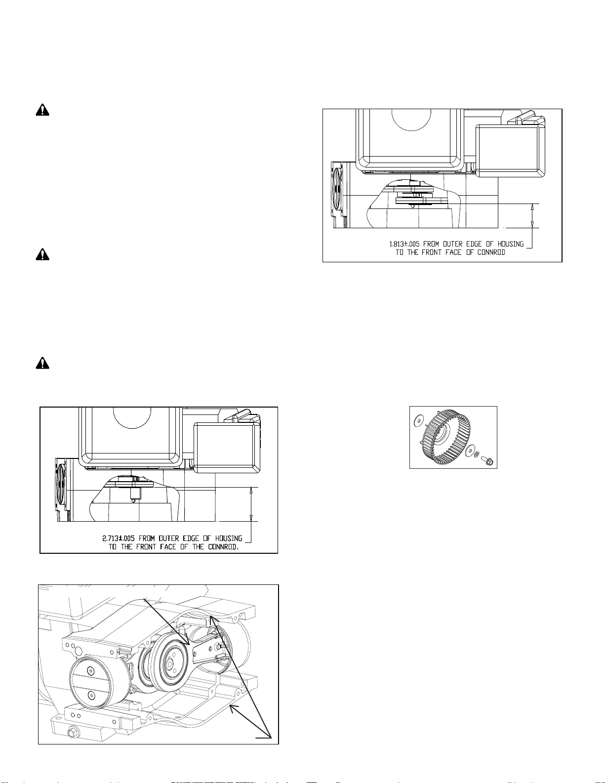
Outer edge of housing
STEP 5. Rotate shaft so the key way is in the 3:00 position, and
using access holes on the top of the housing, insert 1/4” Allen®
hex, and loosen the eccentric set screw. Rotate shaft so that
the key way is now in the 12:00 position, and remove the next
set screw from the eccentric. Slide connecting rod assembly off
and discard.
CAUTION:With a pencil, mark the shaft where the inboard
connecting rod is located. This is only for reference, and not
to be used for exact measurement, or damage will occur.
STEP 6. Rotate shaft so the key way is in the 9:00 position, and
using access holes on the top of the housing, insert 1/4” Allen®
hex, and loosen the eccentric set screw. Rotate shaft so that
the key way is now in the 12:00 position, and remove the next
set screw from the eccentric. Slide connecting rod assembly off
and discard.
Note: Remove the key and discard spring. Replace the key for
assembly.
WARNING: New connecting rod assemblies must hand slide
on shaft without using force.
STEP 7. Rotate shaft so the key way is in the 9:00 position. Slide
inboard connecting rod assembly (stamped “580”) onto shaft
with eccentric in, and the sleeve in the 9:00 position. Do not
remove the sleeve. The distance from the face of the connecting
rod to the edge of the housing must be 2.713 ±.005. Torque the
eccentric screw to 100 in-lbs.
CAUTION: Use the pencil mark only as reference. Using
the mark for the only means of measurement will result in
damage.
STEP 8. Rotate shaft so the key way is in the 3:00 position. Slide
outboard connecting rod assembly (stamped “572”) onto shaft
with eccentric in, and the sleeve in the 3:00 position. Do not
remove the sleeve. The distance from the face of the connecting
rod to the edge of the housing must be 1.813” ±.005. Torque the
eccentric screw to 100 in-lbs.
Front Face of Connecting Rod
STEP 9. Rotate shaft so the key way is in the 12:00 position.
Using a punch, tap in the key until it’s flush to outboard rod
assembly. Using the two access holes in the top of the housing,
torque the two key way set screws to 100 in-lbs.
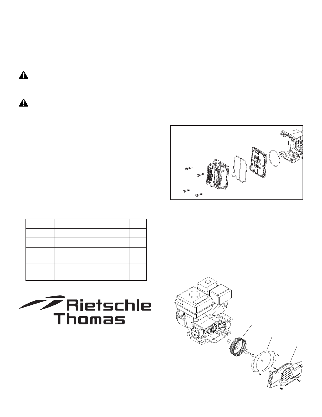
STEP 10. Replace deflector cover. Secure to housing with 4
- Torx® T-25 screws, and torque to 45 in-lbs.
STEP 11. Apply 242 Loctite® to threaded hole of the engine
shaft. Assemble fan, pictured below, and torque screw to 120
- 130 in-lbs.
STEP 12. Obtain one of the heads, and remove the two filter
cover screws using T-25 Torx® screwdriver. Under the filter, locate
the retaining screw, and remove with T-25 Torx® screwdriver.
Flip over to valve plate side, and remove the screw securing the
head. Seperate valve plate from head, remove o-ring, discard,
and replace with new o-ring from kit. Reassemble head and valve
plate. Torque the retaining screw on the head side to 45 in-lbs.
Turn over, torque the screw on the valve plate side to 110 in-lbs.
Reinstall filter. Orient filter cover to head with opening (intake
port) pointing down and torque two screws to 40 - 50 in-lbs.
Repeat this step for other head.
STEP 13. Assemble cylinder sleeve o-ring into groove of valve
plate, and secure to housing using 4 screws, and torque to 110
in-lbs. Check that cross through tube is seated in head. Repeat
this step on other side.
STEP 14. Assemble front cover to housing and torque 4 screws
to 110 in-lbs.
STEP 15. Apply sealant to 2nd - 3rd thread of pipe thread, and
fasten hose to head using 11/16” wrench.
TTable of Contents
Page 7