THOMASVILLE LIGHTING P2528 User manual

THOMASVILLE LIGHTING Lifetime Limited Warranty
THOMASVILLE LIGHTING FAN MOTORS ARE WARRANTED TO THE END USER TO
BE FREE OF ELECTRICAL AND/OR MECHANICAL DEFECTS FOR A LIFETIME FROM
DATE OF SALE. PULL CHAIN SWITCHES, REVERSE SWITCHES, CAPACITORS AND
METAL FINISHES ARE WARRANTED FOR A PERIOD OF 1 YEAR. WARPING OF
WOODEN OR PLASTIC BLADES IS NOT COVERED BY THIS WARRANTY.
THE END USER HAS THE OPTION OF RETURNING THE DEFECTIVE FAN TO THE
PLACE OF PURCHASE DURING THE FIRST 30 DAYS FOR A REPLACEMENT. AFTER
30 DAYS, THE PURCHASER MUST CONTACT THOMASVILLE LIGHTING FOR
REPAIR OR REPLACEMENT. THE END USER ALSO BEARS THE RESPONSIBILITY
FOR ALL COSTS IN THE REMOVAL, SHIPPING AND REINSTALLATION OF FANS OR
PARTS FOR REPAIR OR REPLACEMENT.
THOMASVILLE LIGHTING WILL NOT ASSUME LIABILITY OR RESPONSIBILITY
FOR DAMAGES (INCLUDING INCIDENTAL OR CONSEQUENTIAL) CAUSED BY
THE IMPROPER INSTALLATION OR OPERATION OF THE UNIT OR ITS COMPONENT
PARTS, OR BY THE FAILURE OF SUPPORTING HARDWARE NOT SUPPLIED BY
THOMASVILLE LIGHTING. THIS WARRANTY IS GIVEN IN LIEU OF ALL OTHER
GUARANTEES, WHETHER EXPRESSED OR IMPLIED, AND IS VOIDED IN CASES OF
ABUSE, MISUSE OR IMPROPER HANDLING, NEGLIGENCE, SHIPPING DAMAGE,
UNAUTHORIZED REPAIRS (MADE OR ATTEMPTED) OR UNUSUAL APPLICATION.
SOME STATES DO NOT ALLOW LIMITATIONS ON HOW LONG AN IMPLIED
WARRANTY LASTS OR THE EXCLUSION OR LIMITATIONS OF INCIDENTAL OR
CONSEQUENTIAL DAMAGES, SO THE ABOVE LIMITATIONS AND EXCLUSIONS
MAY NOT APPLY TO YOU. THIS WARRANTY GIVES YOU SPECIFIC RIGHTS AND
YOU MAY HAVE OTHER RIGHTS WHICH VARY FROM STATE TO STATE.
DatePurchased
Store Purchased
ULModelNo. P2528
SerialNo.
Vendor No. 5523
UPC 785247148288
THOMASVILLE LIGHTING Lifetime Limited Warranty
Safety Rules 1
Unpacking Your Fan 2
Installing Your Fan 3
Operating Your Fan 9
Operating Your Remote Control 10
Care of Your Fan 11
Troubleshooting 12
Specifications 13
Table of Contents
1.Safety Rules
READ AND SAVE THESE INSTRUCTIONS
1. To reduce the risk of electric shock, insure electricity has
been turned off at the circuit breaker or fuse box before
beginning.
2. All wiring must be in accordance with the National
Electrical Code ANSI/NFPA 70-1999 and local electrical
codes. Electrical installation should be performed by a
qualified licensed electrician.
3. WARNING: To reduce the risk of fire or electric shock,
this fan should only be used with fan speed control part
no.:UC7067RC manufactured by Rhine Electronic Co., Ltd.
4. CAUTION: To reduce the risk of personal injury, use
only the screws provided with the outlet box.
5. The outlet box and support structure must be securely
mounted and capable of reliably supporting a minimum of 35
pounds. Use only UL Listed outlet boxes marked "FOR FAN
SUPPORT".
WARNING
TO REDUCE THE RISK OF FIRE, ELECTRIC SHOCK OR
PERSONAL INJURY, MOUNT FAN TO OUTLET BOX MARKED
ACCEPTABLE FOR FAN SUPPORT WITH THE SCREWS
PROVIDED WITH THE OUTLET BOX.
6. The fan must be mounted with a minimum of 7 feet
clearance from the trailing edge of the blades to the floor.
7. Avoid placing objects in the path of the blades.
8. To avoid personal injury or damage to the fan and other
items, be cautious when working around or cleaning the fan.
9. Do not use water or detergents when cleaning the fan or
fan blades. A dry dust cloth or lightly dampened cloth will be
suitable for most cleaning.
10. After making electrical connections, spliced conductors
should be turned upward and pushed carefully up into outlet
box. The wires should be spread apart with the grounded
conductor and the equipment-grounding conductor on one side
of the outlet box.
11. Electrical diagrams are for reference only. Light kits that
are not packed with the fan must be UL Listed and marked
suitable for use with the model fan you are installing. Switches
must be UL General Use Switches. Refer to the instructions
packaged with the light kits and switches for proper assembly.
WARNING
TO REDUCE THE RISK OF PERSONAL INJURY, DO NOT BEND
THE BLADE BRACKETS (ALSO REFERRED TO AS "FLANGES")
DURING ASSEMBLY OR AFTER INSTALLATION. DO NOT
INSERT OBJECTS IN THE PATH OF THE BLADES.
WARNING
TO REDUCE THE RISK OF SHOCK. THIS FAN MUST BE
INSTALLED WITH AN ISOLATION WALL CONTROL/SWITCH.
IMPORTANT
PLEASE REMOVE RUBBER MOTOR STOPS ON THE BOTTOM
OF THE FAN BEFORE INSTALLING BLADES OR TESTING
MOTOR.

Unpacking Your Fan 2.
1. Mounting Plate (inside Canopy)
2a. Downrod and Ball Assembly (12”)
(with hanger pin and locking pin
pre-attached)
2b. An Extra Downrod (6”)
3. Canopy
4. Arm Support Ring
5. Decorative Arm (3)
6. Fan Motor Assembly
7. Support Plate
8. Bottom Cover
9. Finial
10. Blade Bracket Set (5)
11. Decorative Motor Collar Cover
12. Extra 45-Degree Canopy Bottom
Cover
13. Hand Unit / Receiver
(a 12V battery included)
14. Blades (5)
15a. Bulbs (6)
(pre-installed in the fan motor
assembly)
15b. An Extra Bulb
a) BladeAttachment Hardware
(15 washer head screws)
b) Extra Blade Bracket Hardware
(1 screw and lockwasher)
c) Electric Hardware & Balancing
Kit
(3 plastic wire connectors, blade
balancing kit)
d) Mounting Hardware (2 extra
mounting screws #10-32 for outlet
box)
Unpack your fan and check the contents. You should have the following items.

Tools Required
Phillips screw driver, straight slot
screw driver, adjustable wrench, step
ladder, and wire cutters.
Mounting Options
If there isn't an existing mounting box,
then read the following instructions.
Disconnect the power by removing
fuses or turning off circuit breakers.
Secure the outlet box directly to the
building structure. Use appropriate
fasteners and building materials. The
outlet box and its support must be able
to fully support the moving weight of
the fan (at least 35 lbs.). Do not use
plastic outlet boxes.
WARNING
TO REDUCE THE RISK OF FIRE,
ELECTRIC SHOCK, OR OTHER
PERSONAL INJURY, MOUNT FAN ONLY
TO AN OUTLET BOX MARKED
ACCEPTABLE FOR FAN SUPPORT AND
USE THE MOUNTING SCREWS PROVIDED
WITH THE OUTLET BOX. OUTLET BOXES
COMMONLY USED FOR THE SUPPORT
OF LIGHTING FIXTURES MAY NOT BE
ACCEPTABLE FOR FAN SUPPORT AND
MAY NEED TO BE REPLACED. CONSULT
A
QUALIFIED ELECTRICIAN IF IN
DOUBT.
Figures l, 2, and 3 are examples of
different ways to mount the outlet box.
Figure 1
Figure 2
Figure 3
Note: You may need a longer
down-rod to maintain proper blade
clearance when installing on a steep,
sloped ceiling. The maximum angle
allowable is 45 degrees. Note: For
mounting angles between 20-45
degrees, please replace the canopy
bottom cover installed on the bottom
of the canopy opening with the extra
45-degree canopy bottom cover
included.
Figure 4
To hang your fan where there is an
existing fixture but no ceiling joist,
you may need an installation hanger
bar as shown in Figure 4 (available at
your Thomasville Lighting Retailer).
3.Installing Your Fan

Hanging the Fan
REMEMBER to turn off the power.
Follow the steps below to hang your fan
properly.
NOTE: This fan is recommended for
the standard ceiling mounting using the
downrod and ball assembly. When
using standard downrod installation, the
distance from the ceiling to the bottom of
the fan blades will be approximately 19
inches.
STANDARD CEILING MOUNTING
The maximum angle allowable is 45
degrees. Note: For mounting angles
between 20-45 degrees, please replace
the canopy bottom cover installed on
the bottom of the canopy opening with
the extra 45-degree canopy bottom
cover included.
1. Remove the canopy ring from the
canopy by turning the ring to the right
until it unlocks. (Figure 5)
2. Remove the mounting plate from the
canopy by loosening the four screws on
the top of the canopy. Remove the two
non-slotted screws and loosen the slotted
screws. This will enable you to remove
the mounting plate (Figure 6).
3. Remove and retain the three screws
on the upper decorative arms. Reinstall
and secure the three screws from the top
of arm support ring into the decorative
arms (Figure A).
4. Repeat steps 3 for the remaining
decorative arms.
Figure 5
Figure 6
Figure A
5. Remove the hanger pin and locking
pin from downrod assembly.
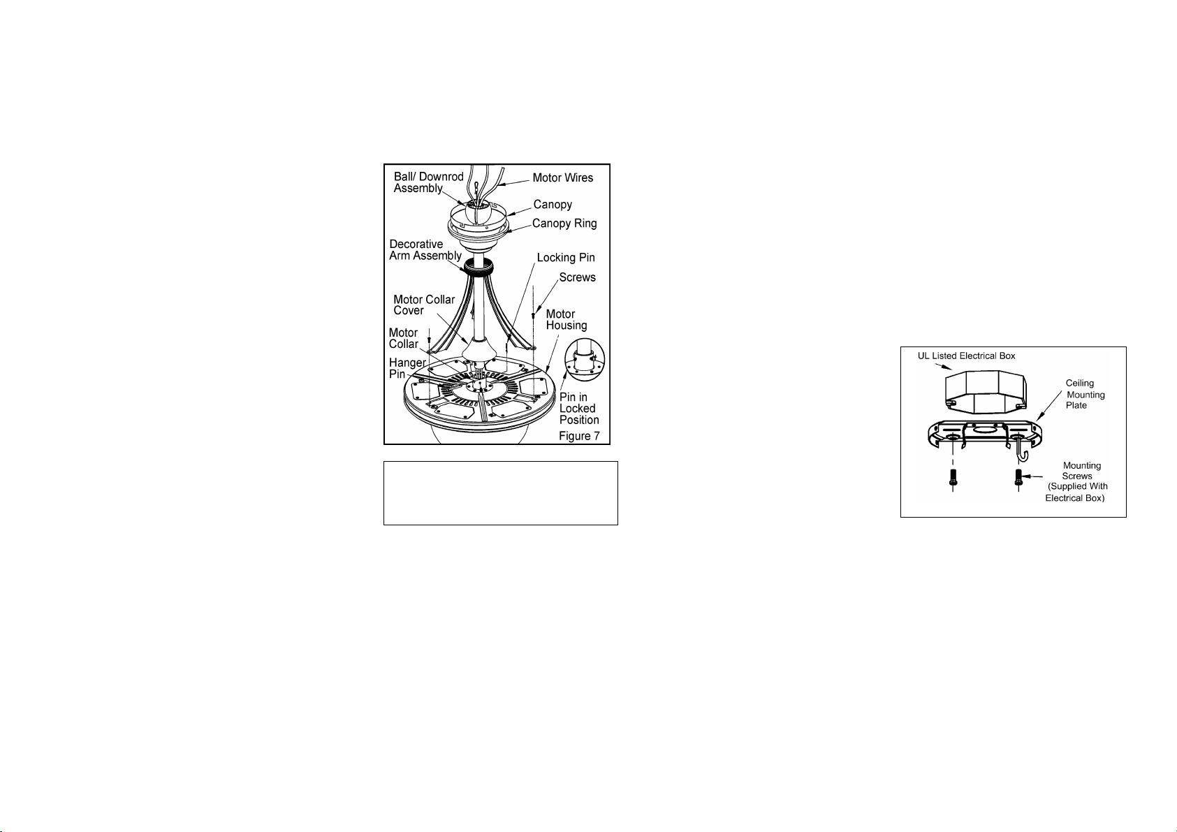
6. Route the wires exiting the top of
the fan motor through the decorative
motor collar cover, decorative arms
assembly, then the canopy ring. Make
sure the slot openings are on top. Route
the wires through the canopy and then
through the ball/downrod assembly
(Figure 7).
7. Loosen, but do not remove, the set
screws on the collar on the top of the
motor housing.
8. Align the holes at the bottom of the
downrod with holes in the collar on top
of the motor housing (Figure 7).
Carefully insert the hanger pin through
the holes in the collar and downrod. Be
careful not to jam the pin against the
wiring inside the downrod. Insert the
locking pin through the hole near the end
of the hanger pin until it snaps into its
locked position as noted in the circle inset
of Figure 7.
9. Re-tighten the set screws on the
collar on the top of the motor housing.
10. Remove and retain the three screws
attaching the upper motor housing.
Reinstall the three screws from the
bottom of decorative arms to the upper
motor housing(Figure 7). 4.
WARNING
FAILURE TO PROPERLY INSTALL LOCKING
PIN AS NOTED IN STEP 8 COULD RESULT
IN FAN LOOSENING AND POSSIBLY
FALLING.
CHANGINGTHE DOWNROD
(OPTIONAL)
An extra 6 inch downrod is supplied with
the fan for close-to the ceiling installation,
please see following steps on changing
the downrod prior to installation. NOTE:
OMIT DECORATIVE ARM
ASSEMBLY WHEN USING THE 6
INCH DOWNROD.
1. Remove the hanger ball by loosening
the set screw at the top of the 12"
downrod assembly which holds the
hanger ball to the downrod (This is not
the screw with green wire attached). Slide
the hanger ball down the downrod and
remove the support pin.
2. Insert the support pin in the holes at
the top of 6" downrod and slide the
hanger ball up to the 6" downrod. Make
sure the support pin is properly seated in
the grooves in the top of the hanger ball.
3. Tighten the set screw firmly.
Installing Fan to the
Electrical Box
1. Pass the 120-volt supply wires through
the center hole in the ceiling mounting
plate as shown in Figure 8.
2. Install the ceiling mounting plate on
the electrical box by mounting screws
provided with the outlet box. Note that
the flat side of the mounting plate is
toward the electrical box (Figure 8).
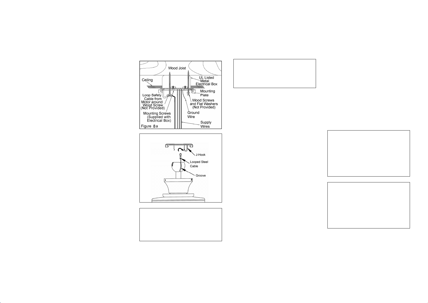
3 Securely tighten the two mounting
screws.
4. For additional security, install two
wood screws with flat washers (not
included) through outer slots in mounting
plate and into wooden joist. Note: Leave
one wood screw untightened to attach
safety cable from motor (Figure 8a).
CONNECTING THE SAFETY
CABLE
a. Place the looped end of the safety
cable around the untightened wood screw
as shown in Figure 8a.
b. Tighten the wood screw securing the
safety cable.
CAUTION: In order to extend the length
of the safety cable, please use braided
steel cable of the same thickness or
greater and secure according to local and
national electric codes. Please consult a
qualified electrician if you are in doubt.
Figure 8
5. Carefully lift the fan assembly up to
the ceiling mounting plate and place the
looped steel cable exiting the
donwrod/ball assembly over the J-hook
on the mounting plate allowing the fan to
be suspended while making the wiring
(Figure 9). 5.
Standard Mounting
WARNING
THE ILLUSTRATION SHOWN IN FIGURE 9
IS ONLY TO PROVIDE A MEANS TO
BALANCE THE FAN WHILE ATTACHING
WIRING. FAILURE TO COMPLETE
INSTALLATION ACCORDING TO THIS
MANUAL WILL RESULT IN DAMAGE TO
PROPERTY AND PERSONAL INJURY.
WARNING
WHEN USING THE STANDARD
BALL/DOWNROD MOUNTING, THE TAB IN
THE RING AT THE BOTTOM OF THE
CANOPY MUST REST IN THE GROOVE OF
THE HANGER BALL.
Making the Electrical
Connections
REMEMBER to disconnect the power. If
you feel that you do not have enough
electrical wiring knowledge or experience,
have your fan installed by a licensed
electrician.
Follow the steps below to connect the fan
to your household wiring. Use the wire
connecting nuts supplied with your fan and
supplied with remote control. Secure the
connectors with electrical tape. Make sure
there are no loose strands or connections
(Figure 10).
l. Connect both green wires from the
downrod and mounting plate to the bare
copper (Ground) from the electrical box.
2. Connect the black wire (AC IN L)
from the receiver unit to the black wire
from the electrical box.
3. Connect the white wire (AC IN N)
from the receiver unit to the white wire
from the electrical box.
4. Connect the white wire (To Motor N)
from the receiver unit to the white wire
from the fan assembly.
5. Connect the black wire (To Motor L)
from the receiver unit to the black wire
from the fan assembly.
6. Connect the blue wire (For Light)
from the receiver unit to the blue wire
from the fan.
After wires are connected, carefully tuck
them into the electrical box. Insert the
receiver unit into the mounting plate;
make sure the black antenna wire sits on
top of the receiver unit.
NOTE
THE FREQUENCIES ON YOUR RECEIVER
AND TRANSMITTER HAVE BEEN PRESET AT
THE FACTORY, BEFORE INSTALLING THE
RECEIVER, MAKE SURE THE DIP SWITCHES
ON THE RECEIVER AND TRANSMITTER ARE
SET TO THE SAME FREQUENCY. THE DIP
SWITCHES ON THE TRANSMITTER ARE
LOCATED INSIDE THE BATTERY
COMPARTMENT.
WARNING
EACH WIRE NUT (WIRE CONNECTOR)
SUPPLIED WITH THIS FAN IS DESIGNED TO
ACCEPT UP TO ONE 12 GAUGE HOUSE WIRE
AND TWO WIRES FROM THE FAN. IF YOU
HAVE LARGER THAN 12 GAUGE HOUSE
WIRING OR MORE THAN ONE HOUSE WIRE
TO CONNECT TO THE FAN WIRING,
CONSULT AN ELECTRICIAN FOR THE
PROPER SIZE WIRE NUTS TO USE. 6.
Figure 9
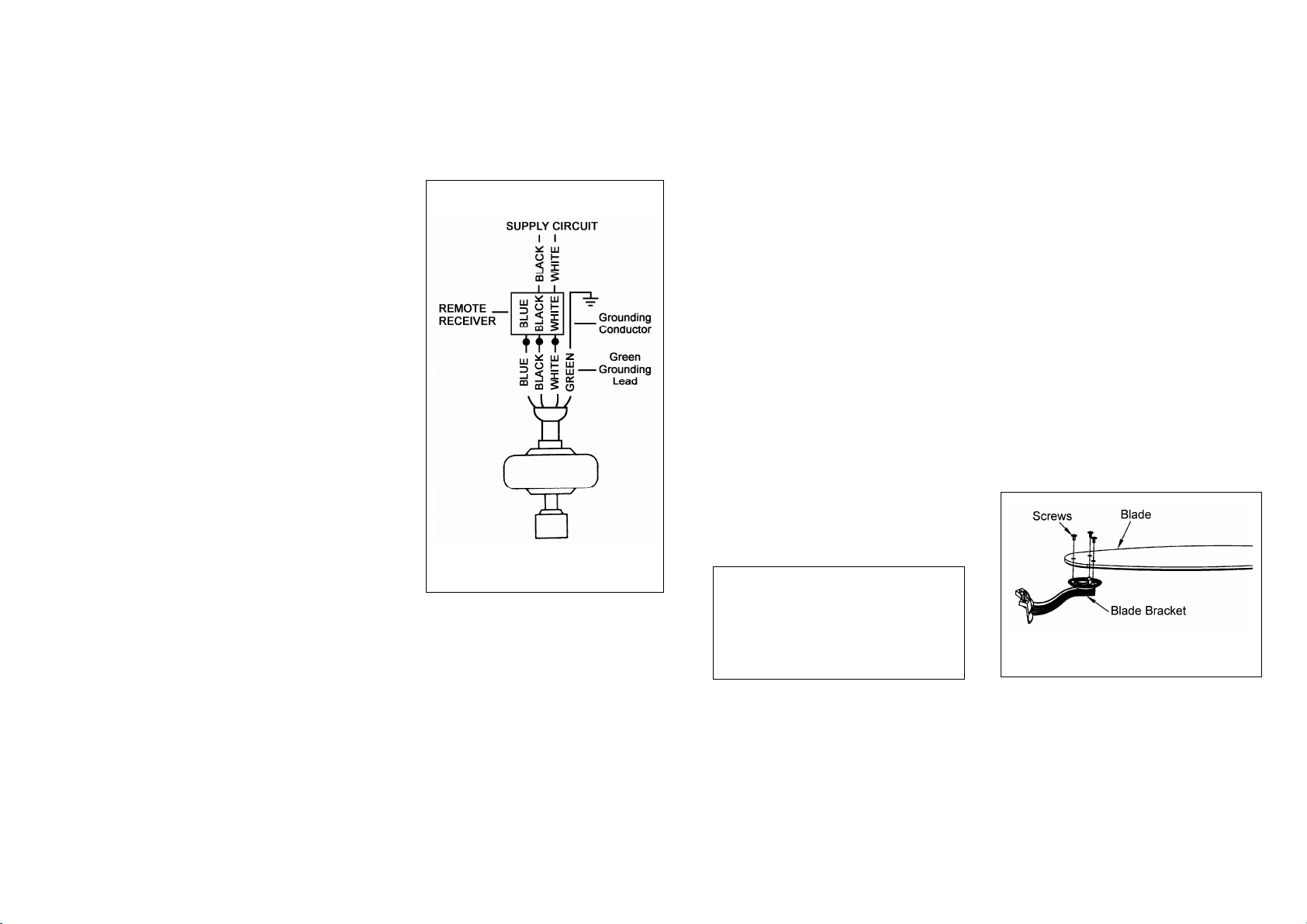
Figure 10
.
7.
Finishing the Fan
Installation
1. Carefully lift the canopy up to the
mounting plate . Make sure the tab in the
ring at the bottom of the canopy is
properly seated in the groove in the hanger
ball. Align the locking slots of the ceiling
canopy with the two screws in the
mounting plate. Push up to engage the
slots and turn clockwise to lock in place.
Immediately tighten the two mounting
screws firmly.
2. Install the remaining two mounting
screws into the holes in the canopy and
tighten firmly.
3. Install the decorative canopy ring by
aligning the ring’s slots with the screws in
the canopy. Rotate the ring
counter-clockwise to lock in place.
4. You may now proceed to attaching the
fan blades. WARNING
LOCKING SLOTS OF CEILING
CANOPY ARE PROVIDED ONLY AS
AN AID TO MOUNTING. DO NOT
LEAVE FAN ASSEMBLY UNATTENDED
UNTIL ALL FOUR CANOPY SCREWS
ARE ENGAGED AND FIRMLY
TIGHTENED.
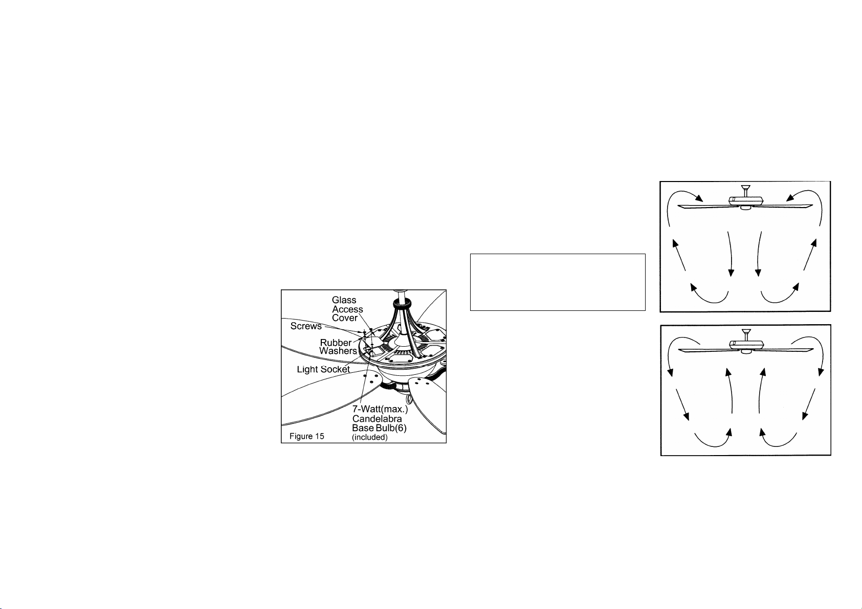
Attaching the Fan
Blades
1. Attach blade to blade bracket using
the screws as shown in Figure 11. Please
note that the rubber washers are pre-
attached to the blade bracket. Start a
screw into the bracket. Repeat for the
two remaining screws.
2. Tighten each screw securely.
3. Fasten the blade assembly to the motor
by inserting the alignment post into the
slot on the bottom of the motor and
tightening the motor screws. Please note
that the motor screws are pre-attached
into the blade brackets (Figure 12).
4. Repeat steps 1, 2 & 3 for the remaining
blades.
Figure 11

Blade Balancing
All blades are grouped by weight.
Because natural woods vary in density,
the fan may wobble even though the
blades are weight matched. The following
procedure should correct most fan wobble.
Check after each step.
1. Check that all blade and blade
bracket screws are secure. Most fan
wobble problems are caused when blade
levels are unequal. Check this level by
selecting a point on the ceiling above the
tip of one of the blades. Measure from a
point on the center of each blade to the
8.
point on the ceiling. Measure this
distance as shown in Figure 13. Rotate
the fan until the next blade is positioned
for measurement. Repeat for each blade.
Measurements deviation should be within
1/8". Run the fan for 10 minutes.
2. Use the enclosed Blade Balancing
Kit if the blade wobble is still noticeable.
NOTE
NOTE: WAIT FOR FAN TO STOP BEFORE
REVERSING THE DIRECTION OF BLADE
ROTATION.
WARNING
TO REDUCE THE RISK OF PERSONAL
INJURY, DO NOT BEND THE BLADE
HOLDERS WHILE INSTALLING,
BALANCING THE BLADES, OR CLEANING
THE FAN, DO NOT INSERT FOREIGN
OBJECTS BETWEEN ROTATING FAN
BLADES.
Attaching the Support
Plate / Bottom Cover
1. Remove one screw from the
mounting adaptor below the fan motor
assembly. Loosen, but do not remove the
other two screws, see Figure 14.
2. Align the keyhole slots in the
support plate with the two screws in the
mounting adaptor.
3. Turn the support plate clockwise
until the two screws are situated in the
narrow end of the keyhole slots as shown
in the circle insert of Figure 14.
4. Re-install one screw that was
removed in step 1. Tighten all three
screws firmly.
5. Raise the bottom cover up against
the light kit asssembly and secure
properly with finial (Figure 14).
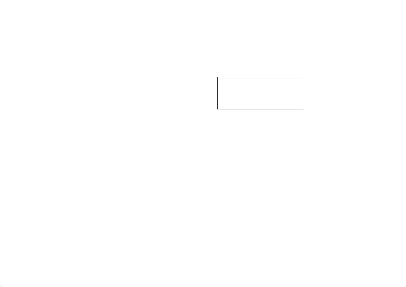
Lighted Housing Bulb
Replacement
WHILE PERFORMING BULB
REPLACEMENT, IT IS
RECOMMENDED TO PERFORM BY A
QUALIFIED LICENSED
ELECTRICAN.
CAUTION-Reduce the risk of electrical
shock, disconnect the electrical support
circuit to the fan before installing light
kit.
1. Remove two screws and washers on
the glass access cover that secure in the
motor housing (Figure 15).
2. Remove the glass access cover to
expose the bulb.
3. Replace the bulb with 7W, 120VAC
candelabra base bulb only.
4. Re-attach the glass access cover to
the motor housing using two screws and
washers removed in step 1.
NOTE: ALLOW THE BULBS TO
COOL COMPLETELY BEFORE
TOUCHING OR REPLACING THE
BULBS TO AVOID ACCIDENTAL
BURNING OF THE SKIN.
FAN REVERSE CONTROL
NOTE
DO NOT WAIT FOR THE FAN TO STOP TO
PRESS THE REVERSE BUTTON. THE FAN
WILL NOT REVERSE IF THE FAN IS NOT
MOVING.
The hand unit controls directions
(forward or reverse).
Speed settings for warm or cool weather
depend on factors such as the room size,
ceiling height, number of fans, and so on.
Warm weather- (Forward) A downward
air flow creates a cooling effect as shown
in Figure 16. This allows you to set your
air conditioner on a higher setting without
affecting your comfort.
Cool weather- (Reverse) An upward
airflow moves warm air off the ceiling
area as shown in Figure 17. This allows
you to set your heating unit on a lower
setting without affecting your comfort.
9.Operating Your Fan
Figure 17
Figure 16

O
p
eratin
g
Your Remote Control 10.
Setting the Code
This unit has 16 different code combinations.
To set the code, perform the following steps.
A. Setting the code on the transmitter:
a. Remove the battery cover from the battery
compartment in the back side of the transmitter.
b. Slide code switches to your choice of up or down
position (factory setting is all up).
B. Setting the code on the receiver:
a. Slide code switches to the same position as set on
your transmitter.
b. Re-place the battery cover on the battery compartment
of the transmitter.
CAUTION: Ceiling angle shall not exceed 45 degrees.
Remote Control Model: UC7067RC
Installing Receiver
WARNING: To reduce the risk of fire or electric shock,
remember to disconnect power. Do not use solid state fans,
electrical wire must meet all local and national electrical code
requirement. Electrical source and fans must be 115/120 volt,
60Hz. Maximum fan motor amps: 1.0. Maximum light watts:
300-incandescent only.
A. Wire connection:
Fan Green Wire Bare Supply Wire
Black Receiver Wire (AC IN L) Black Supply Wire
White Receiver Wire(AC IN N) White Supply Wire
White receiver Wire(TO MOTOR N) White Fan Wire
Black Receiver Wire(TO MOTOR L) Black Fan Wire
Blue Receiver Wire(FOR LIGHT) Blue Light Wire
NOTE: If other fan or supply wires are different color, have
this unit installed by a licensed electrician.
B. Lay the black antenna wire on top of the receiver and slide
the receiver into the mounting plate.
Operating Transmitter
Install a 12 volt battery ( included).
This remote is equipped with 16 code combinations. To
prevent possible interference from or to other remote units
such as garage door openers, car alarm or security system,
simply change the combination code but be sure that the code
on both transmitter and receiver are matched.
This device complies with part 15 of the FCC rules. Operation
is subject to the following two conditions:(1) This device may
not cause harmful interference and (2) This device must accept
any interference received, including interference that may
cause undesired operation.
Operating the fan:
●●● Key---High Speed
●● Key--Medium Speed
●Key---LowSpeed
Key---Light On/Off and Dimmer
Key (inside the battery compartment in the back side of
the transmitter) -Fan Reversing Function
■ Key---Fan Off
11.Care of Your Fan
Here are some suggestions to help you
maintain your fan.
1. Because of the fan's natural
movement, some connections may
become loose. Check the support
connections, brackets, and blade
attachments twice a year. Make sure
they are secure. (It is not necessary to
remove fan from ceiling.)
2. Clean your fan periodically to
help maintain its new appearance over
the years. Do not use water when
cleaning. Use only a soft brush or
lint-free cloth to avoid scratching the
finish. The plating is sealed with a
lacquer to minimize discoloration or
tarnishing. This could damage the
motor, or the wood or possibly cause
an electrical shock.
3. You can apply a light coat of
furniture polish to the wood for
additional protection and enhanced
beauty. Cover small scratches with a
light application of shoe polish.
4. There is no need to oil your fan.
The motor has permanently lubricated
sealed ball bearings.
WARNING
MAKE SURE THE POWER IS OFF AT THE
ELECTRICAL PANEL BOX BEFORE YOU
ATTEMPT ANY REPAIRS. REFER TO THE
SECTION, "MAKING ELECTRICAL
CONNECTIONS."

Troubleshooting 12.
Problem Solution
Fan will not start.
Fan sounds noisy.
1. Check main and branch circuit fuses or breakers.
2. Check line wire connections to the fan and switch wire connections in the switch housing.
CAUTION: Make sure main power is off.
3. Check battery in the transmitter. Does the red LED light come on? Are you standing close
enough to the fan (normal range is 10-20 feet)? Are the dip switch settings the same on the
transmitter (hand unit) and receiver? REMEMBER TO TURN OFF POWER SUPPLY
BEFORE CHECKING THE DIP SWITCH SETTINGS IN RECEIVER.
1. Make sure all motor housing screws are snug.
2. Make sure the screws that attach the fan blade bracket to the motor hub are tight.
3. Make sure wire nut connections are not rattling against each other or the interior wall of the
switch housing.
CAUTION: Make sure main power is off.
4. Allow a 24-hour "breaking-in" period. Most noises associated with a new fan disappear during
this time.
5. If using the Ceiling Fan light kit, make sure the screws securing the glassware are tight. Check
that the light bulb is also secure.
6. Make sure the canopy is a short distance from the ceiling.
It should not touch the ceiling.
7. Make sure your ceiling box is secure and rubber isolator pads were used between the hanger
bracket and ceiling box.
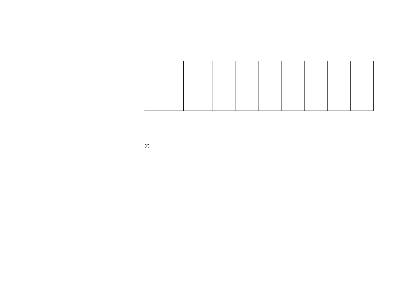
FAN SIZE SPEED VOLTS AMPS WATTS RPM N.W. G.W. C.F.
Low 120 0.34 12.7 50
Med. 120 0.48 32.0 80
58”
High 120 0.64 76.5 135
29.9
Lbs
37.4
Lbs 3.5
These are approximate measures. They do not include Amps and Wattage used by the light kit.
2007 Thomasville Lighting Inc.
701 Millennium Blvd.,
Greenville, SC 29607
All Rights Reserved
13.Specifications
This manual suits for next models
1
Table of contents
Other THOMASVILLE LIGHTING Fan manuals


