Thomasville Carmel P2505 User manual
P2505
C e i l i n g F a n I n s t a l l a t i o n M a n u a l
L I G H T I N G
TM
Carmel
collection

THOMASVILLE LIGHTING Lifetime Limited Warranty
THOMASVILLE LIGHTING FAN MOTORS ARE WARRANTED TO THE END USER TO
BE FREE OF ELECTRICAL AND/OR MECHANICAL DEFECTS FOR A LIFETIME FROM
DATE OF SALE. PULL CHAIN SWITCHES, REVERSE SWITCHES, CAPACITORS AND
METAL FINISHES ARE WARRANTED FOR A PERIOD OF 1 YEAR. WARPING OF
WOODEN OR PLASTIC BLADES IS NOT COVERED BY THIS WARRANTY.
THE END USER HAS THE OPTION OF RETURNING THE DEFECTIVE FAN TO THE
PLACE OF PURCHASE DURING THE FIRST 30 DAYS FOR A REPLACEMENT. AFTER
30 DAYS, THE PURCHASER MUST CONTACT THOMASVILLE LIGHTING FOR
REPAIR OR REPLACEMENT. THE END USER ALSO BEARS THE RESPONSIBILITY
FOR ALL COSTS IN THE REMOVAL, SHIPPING AND REINSTALLATION OF FANS OR
PARTS FOR REPAIR OR REPLACEMENT.
THOMASVILLE LIGHTING WILL NOT ASSUME LIABILITY OR RESPONSIBILITY
FOR DAMAGES (INCLUDING INCIDENTAL OR CONSEQUENTIAL) CAUSED BY
THE IMPROPER INSTALLATION OR OPERATION OF THE UNIT OR ITS COMPONENT
PARTS, OR BY THE FAILURE OF SUPPORTING HARDWARE NOT SUPPLIED BY
THOMASVILLE LIGHTING. THIS WARRANTY IS GIVEN IN LIEU OF ALL OTHER
GUARANTEES, WHETHER EXPRESSED OR IMPLIED, AND IS VOIDED IN CASES OF
ABUSE, MISUSE OR IMPROPER HANDLING, NEGLIGENCE, SHIPPING DAMAGE,
UNAUTHORIZED REPAIRS (MADE OR ATTEMPTED) OR UNUSUAL APPLICATION.
SOME STATES DO NOT ALLOW LIMITATIONS ON HOW LONG AN IMPLIED
WARRANTY LASTS OR THE EXCLUSION OR LIMITATIONS OF INCIDENTAL OR
CONSEQUENTIAL DAMAGES, SO THE ABOVE LIMITATIONS AND EXCLUSIONS
MAY NOT APPLY TO YOU. THIS WARRANTY GIVES YOU SPECIFIC RIGHTS AND
YOU MAY HAVE OTHER RIGHTS WHICH VARY FROM STATE TO STATE.
DatePurchased
Store Purchased
ULModelNo. 54-TS
SerialNo.
Vendor No. 5523
UPC 785247128389
THOMASVILLE LIGHTING Lifetime Limited Warranty

Safety Rules 1
Unpacking Your Fan 2
Installing Your Fan 3
Operating Your Fan 11
Operating Your Remote Control 12
Care of Your Fan 13
Troubleshooting 14
Specifications 15
Table of Contents

1.Safety Rules
READ AND SAVE THESE INSTRUCTIONS
1. To reduce the risk of electric shock, insure electricity has
been turned off at the circuit breaker or fuse box before
beginning.
2. All wiring must be in accordance with the National
Electrical Code ANSI/NFPA 70-1999 and local electrical
codes. Electrical installation should be performed by a
qualified licensed electrician.
3. WARNING: To reduce the risk of fire or electric shock,
this fan should only be used with fan speed control part
no.:UC7067RYL manufactured by Rhine Electronic Co., Ltd.
4. CAUTION: To reduce the risk of personal injury, use
only the screws provided with the outlet box.
5. The outlet box and support structure must be securely
mounted and capable of reliably supporting a minimum of 50
pounds. Use only UL Listed outlet boxes marked "Acceptable
for fan support of 22.7 kgs (50 lbs) or less".
WARNING
TO REDUCE THE RISK OF FIRE, ELECTRIC SHOCK OR PERSONAL
INJURY, MOUNT TO OUTLET BOX MARKED ACCEPTABLE FOR FAN
SUPPORT OF 22.7 KGS (50 LBS) OR LESS AND USE SCREWS
PROVIDED WITH THE OUTLET BOX.
6. The fan must be mounted with a minimum of 7 feet
clearance from the trailing edge of the blades to the floor.
7. Avoid placing objects in the path of the blades.
8. To avoid personal injury or damage to the fan and other
items, be cautious when working around or cleaning the fan.
9. Do not use water or detergents when cleaning the fan or
fan blades. A dry dust cloth or lightly dampened cloth will be
suitable for most cleaning.
10. After making electrical connections, spliced conductors
should be turned upward and pushed carefully up into outlet
box. The wires should be spread apart with the grounded
conductor and the equipment-grounding conductor on one side
of the outlet box.
11. Electrical diagrams are for reference only. Light kits that
are not packed with the fan must be UL Listed and marked
suitable for use with the model fan you are installing. Switches
must be UL General Use Switches. Refer to the instructions
packaged with the light kits and switches for proper assembly.
WARNING
TO REDUCE THE RISK OF PERSONAL INJURY, DO NOT BEND
THE BLADE BRACKETS (ALSO REFERRED TO AS "FLANGES")
DURING ASSEMBLY OR AFTER INSTALLATION. DO NOT
INSERT OBJECTS IN THE PATH OF THE BLADES.
WARNING
TO REDUCE THE RISK OF SHOCK. THIS FAN MUST BE
INSTALLED WITH AN ISOLATION WALL CONTROL/SWITCH.
WARNING
THIS PRODUCT CONTAINS CHEMICALS KNOWN TO THE STATE
OF CALIFORNIA TO CAUSE CANCER, BIRTH DEFECTS AND/OR
OTHER REPRODUCTIVE HARM. THOROUGHLY WASH HANDS
AFTER INSTALLING, HANDLING, CLEANING, OR OTHERWISE
TOUCHING THIS PRODUCT.

Unpacking Your Fan 2.
1. Mounting Plate (inside Canopy)
2. Downrod and Ball Assembly
(with hanger pin and locking pin
pre-attached)
3. Canopy
4. Decorative Motor Collar Cover
5. Fan Motor Assembly
6. Light Kit Assembly
7. Glass Shade
8. Blade Brackets (5)
(with blade bracket screws
pre-installed)
9. Blades (5)
10. Bottom Cover
11. Finial and Threaded Tube
12. Hand Unit/ Receiver
(a 12V battery included)
13. Extra 45-degree Canopy Bottom Cover
a) Blade Attachment Hardware
(15 washer head screws)
b) Mounting Hardware
(1 plastic gasket, 1 metal gasket, 3
screws & lock-washers)
c) Electric Hardware & Balancing
Kit
(3 plastic wire connectors, blade
balancing kit)
d) Mounting Hardware (2 extra
mounting screws #10-32 for outlet
box)
IMPORTANT
PLEASE REMOVE RUBBER STOPS FROM THE FAN
MOTOR BEFORE INSTALLING BLADES OR TESTING
MOTOR.
14. Bulbs (2)
14
Tools Required
Phillips screw driver, straight slot
screw driver, adjustable wrench, step
ladder, and wire cutters.
Mounting Options
If there isn't an existing mounting box,
then read the following instructions.
Disconnect the power by removing
fuses or turning off circuit breakers.
Secure the outlet box directly to the
building structure. Use appropriate
fasteners and building materials. The
outlet box and its support must be able
to fully support the moving weight of
the fan (at least 50 lbs.). Do not use
plastic outlet boxes.
WARNING
TO REDUCE THE RISK OF FIRE,
ELECTRIC SHOCK, OR OTHER
PERSONAL INJURY, MOUNT FAN ONLY TO
AN OUTLET BOX MARKED OF 22.7 KGS
(50 LBS) OR LESS AND USE THE
MOUNTING SCREWS PROVIDED WITH
THE OUTLET BOX. OUTLET BOXES
COMMONLY USED FOR THE SUPPORT OF
LIGHTING FIXTURES MAY NOT BE
ACCEPTABLE FOR FAN SUPPORT AND
MAY NEED TO BE REPLACED. CONSULT A
QUALIFIED ELECTRICIAN IF IN
DOUBT.
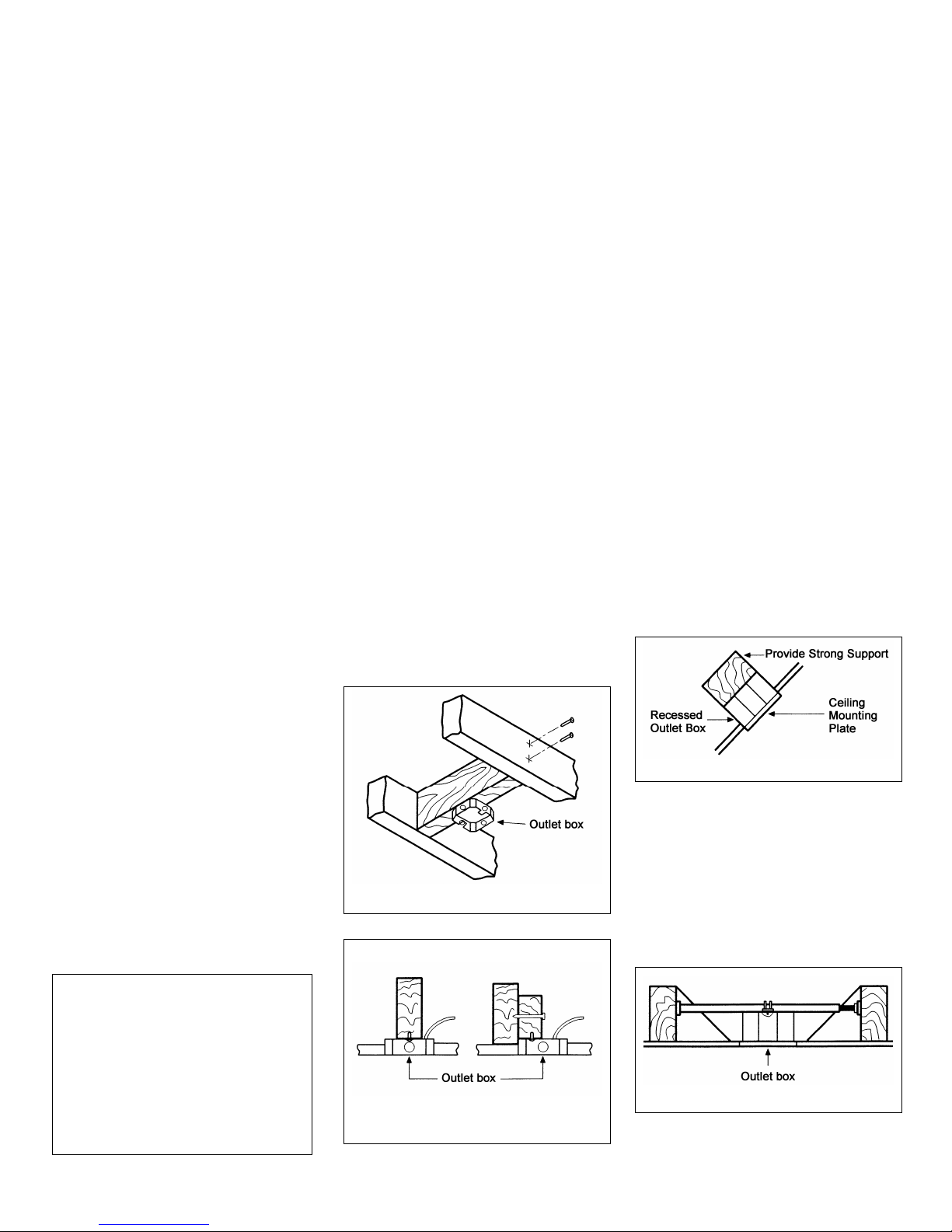
Figures l, 2, and 3 are examples of
different ways to mount the outlet box.
Figure 1
Figure 2
Figure 3
Note: You may need a longer
down-rod to maintain proper blade
clearance when installing on a steep,
sloped ceiling. The maximum angle
allowable is 45 degrees. Note: For
mounting angles between 20-45
degrees, please replace the canopy
bottom cover installed on the bottom
of the canopy opening with the extra
45-degree canopy bottom cover
included.
Figure 4
To hang your fan where there is an
existing fixture but no ceiling joist,
you may need an installation hanger
bar as shown in Figure 4 (available at
your Thomasville Lighting Retailer).
3.Installing Your Fan

Hanging the Fan
REMEMBER to turn off the power.
Follow the steps below to hang your
fan properly.
NOTE: This ceiling fan is supplied
with two types of hanging assemblies;
the standard ceiling installation using
the ball/ downrod assembly mounting,
and the "close-to-ceiling" mounting.
The "close-to-ceiling" mounting is
recommended in rooms with less than
8-foot ceilings or in areas where
additional space is desired from the
floor to the fan blades. When using
standard downrod installation, the
distance from the ceiling to the bottom
of the fan blades will be approximately
13 inches. The "close-to-ceiling"
installation reduces the distance from
the ceiling to the bottom of the fan
blades to approximately 8 inches.
STANDARD CEILING MOUNTING
Note: For mounting angles between
20-45 degrees, please replace the
canopy bottom cover installed on the
bottom of the canopy opening with
the extra 45-degree canopy bottom
cover included.
1. Remove the canopy ring from the
canopy by turning the ring to the right
until it unlocks (Figure5).
Figure 5
2. Remove the mounting plate from
the canopy by loosening the four
screws on the top of the canopy.
Remove the two non-slotted screws
and loosen the slotted screws. This will
enable you to remove the mounting
plate (Figure 6).
Figure 6
3. Remove the hanger pin and
locking pin from downrod assembly.
4. Route the wires exiting the top of
the fan motor through the decorative
motor collar cover then the canopy
ring. Make sure the slot openings are
on top. Route the wires through the
canopy and then through the
ball/downrod assembly (Figure 7).
5. Loosen, but do not remove, the set
screws on the collar on the top of the
motor housing.
4.
6. Align the holes at the bottom of
the downrod with holes in the collar on
top of the motor housing (Figure 7).
Carefully insert the hanger pin through
the holes in the collar and downrod. Be
careful not to jam the pin against the
wiring inside the downrod. Insert the
locking pin through the hole near the
end of the hanger pin until it snaps into
its locked position as noted in the
circle inset of Figure 7.
7. Re-tighten the set screws on the
collar on the top of the motor housing.
WARNING
FAILURE TO PROPERLY INSTALL
LOCKING PIN AS NOTED IN STEP 6
COULD RESULT IN FAN LOOSENING AND
POSSIBLY FALLING.
CLOSE-TO-CEILING
MOUNTING
1. Remove the canopy ring from the
canopy by turning the ring to the right
until it unlocks (Figure 5).
2. Remove the mounting plate from
the canopy by loosening the four
screws on the top of the canopy.
Remove the two non-slotted screws
and loosen the slotted screws. This
will enable you to remove the
mounting plate (Figure 6).
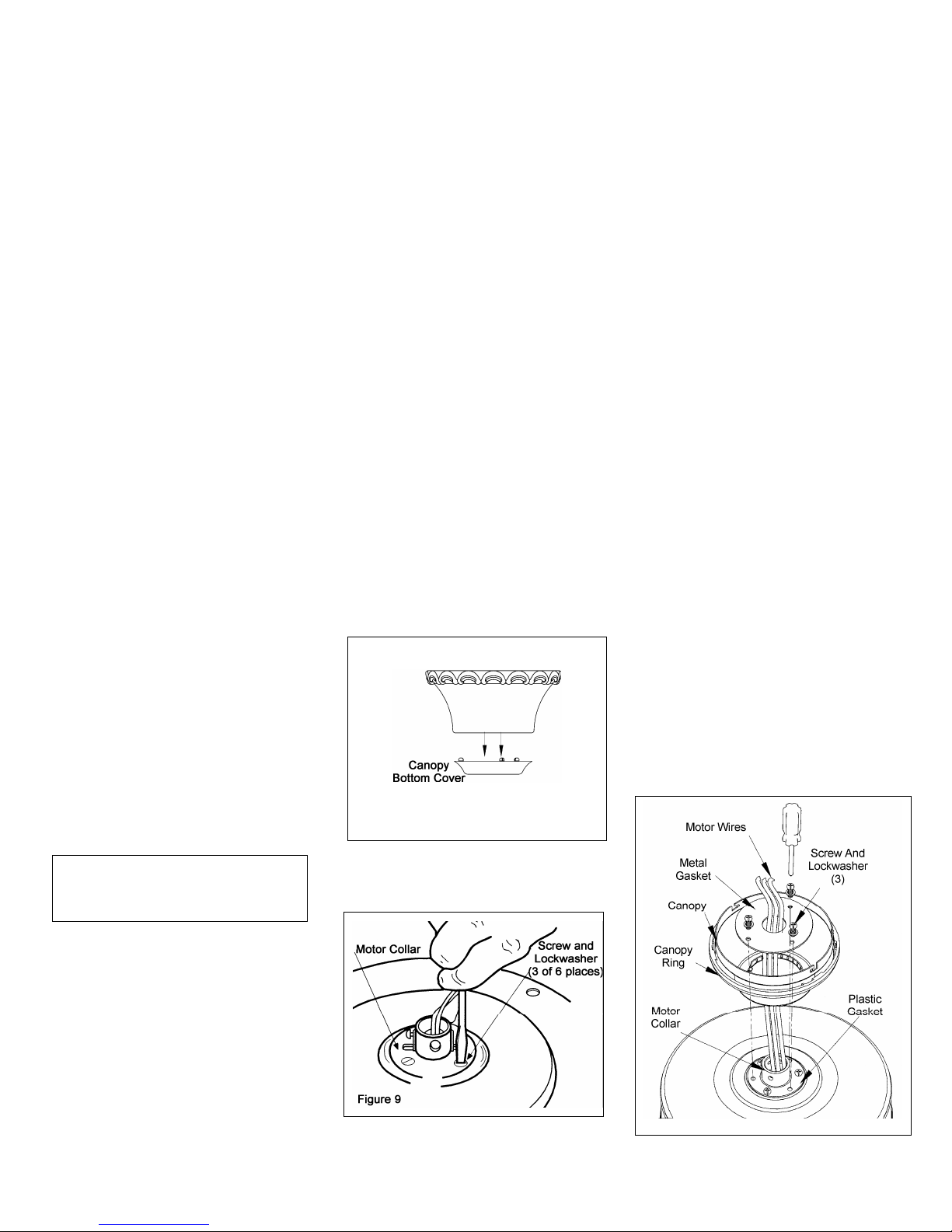
3. Remove the decorative canopy
bottom cover from the canopy by
depressing the three studs (Figure 8).
Figure 8
4. Remove three of the six screws and
lockwashers (every other one) securing
the motor collar to the top of the fan
motor housing (Figure 9).
5. Route the wires exiting the top of the
fan motor through the plastic gasket,
canopy ring, canopy and the metal
gasket, place the plastic gasket over the
remaining three screws, place the
canopy ring, canopy and the metal
gasket over the motor collar at the top
of the fan motor (Figure 10).
6. Align the three mounting screw holes
on the metal gasket with the holes on
the motor collar at the top of the fan
motor and fasten, using the three screws
and lockwashers provided with metal
gasket.
7. Tighten the three mounting screws
securely.
Figure 10
5.
Installing Fan to the
Electrical Box
THE OUTLET BOX AND
SUPPORT STRUCTURE MUST
BE SECURELY MOUNTED AND
CAPABLE OF RELIABLY
SUPPORTING A MINIMUM OF
50 POUNDS. USE ONLY UL
LISTED OUTLET BOXES
MARKED “ACCEPTABLE FOR
FAN SUPPORT OF 22.7 KGS (50
LBS) OR LESS”.
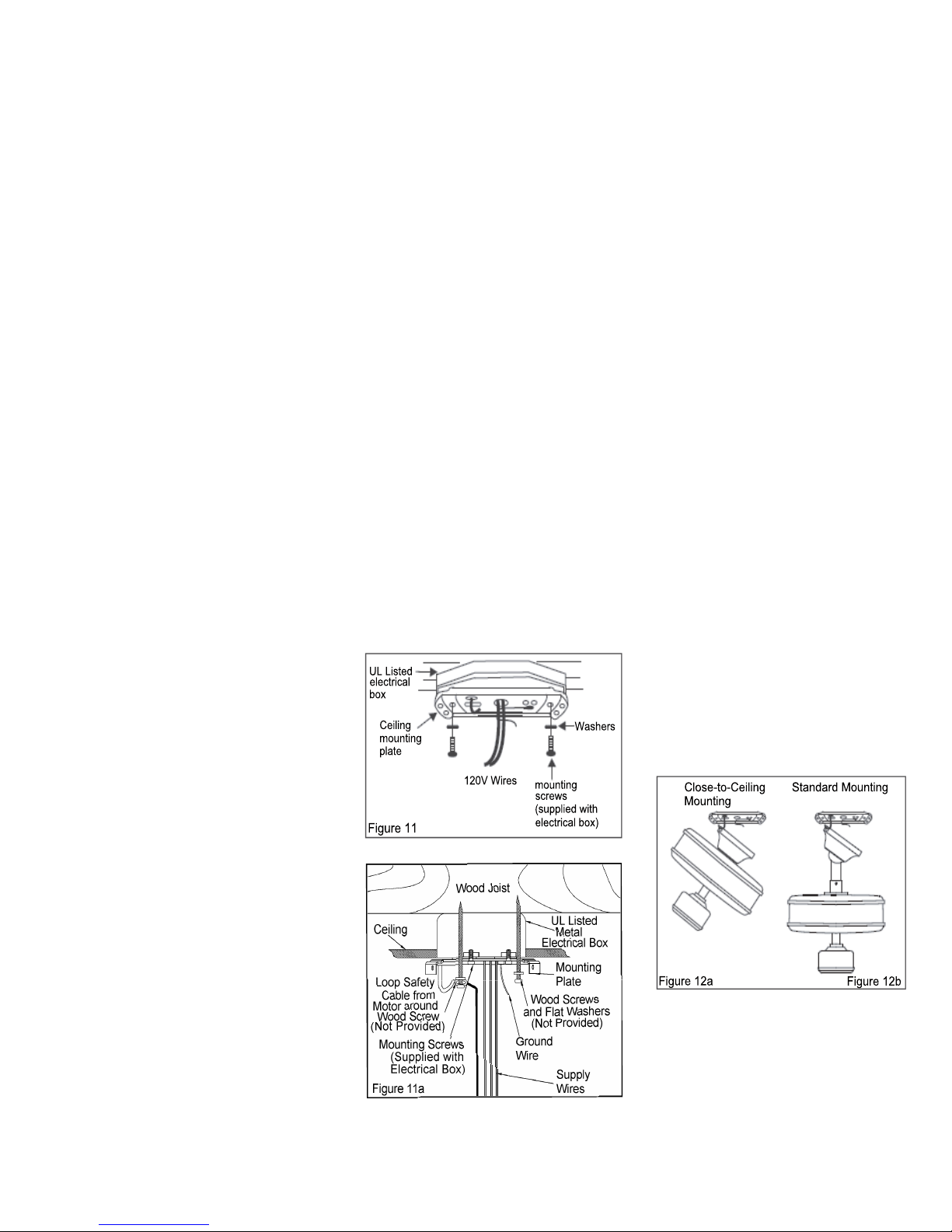
1. Pass the 120-volt supply wires
through the center hole in the ceiling
mounting plate as shown in Fig.11.
2. Install the ceiling mounting plate
on the electrical box by using the mou-
nting screws provided with the electri-
cal box.When using the close-to-ceiling
mounting, it is important that the moun-
ting plate be level. If necessary, use lev-
eling washers(not supplied)between the
mounting plate and electrical box. Note
that the flat side of the mounting plate is
toward the electrical box.(Fig.11)
3. Tighten the two screws on the elec-
trical box securely.
6.
CONNECTING THE SAFETY
CABLE
a. Place the looped end of the safety
cable around the untightened wood
screw as shown in Figure 11a.
b. Tighten the wood screw securing
the safety cable.
CAUTION: In order to extend the
length of the safety cable, please use
braided steel cable of the same
thickness or greater and secure
according to local and national electric
codes. Please Consult a qualified
electrician if you are in doubt.
4. Carefully lift the fan assembly up to
the ceiling mounting plate and hang the
fan on the hook provided by utilizing
one of the holes at the outer rim of the
ceiling canopy.(Fig.12a,12b)

Making the Electrical
Connections
REMEMBER to disconnect the power.
If you feel that you do not have enough
electrical wiring knowledge or
experience, have your fan installed by a
licensed electrician.
Follow the steps below to connect the
fan to your household wiring. Use the
wire connecting nuts supplied with your
fan and supplied with remote control.
Secure the connectors with electrical
tape. Make sure there are no loose
strands or connections (Figure 13).
l. Connect both green wires from the
down-rod and mounting plate to the
bare copper (Ground) from the electrical
box.
2. Connect the black wire (AC IN L)
from the receiver unit to the black wire
from the electrical box.
3. Connect the white wire (AC IN N)
from the receiver unit to the white wire
from the electrical box.
4. Connect the white wire (To Motor
N) from the receiver unit to the white
wire from the fan assembly.
5. Connect the black wire (To Motor
L) from the receiver to the black wire
from the fan assembly.
6. Connect the blue wire (For Light.)
from the receiver to the blue wire from
the fan.
After wires are connected, carefully
tuck them into the electrical box. Insert
the receiver unit into the mounting
plate; make sure the black antenna wire
sits on top of the receiver unit.
NOTE
THE FREQUENCIES ON YOUR RECEIVER
AND TRANSMITTER HAVE BEEN PRESET AT
THE FACTORY, BEFORE INSTALLING THE
RECEIVER, MAKE SURE THE DIP SWITCHES
ON THE RECEIVER AND TRANSMITTER ARE
SET TO THE SAME FREQUENCY. THE DIP
SWITCHES ON THE TRANSMITTER ARE
LOCATED INSIDE THE BATTERY
COMPARTMENT.
WARNING
EACH WIRE NUT (WIRE CONNECTOR)
SUPPLIED WITH THIS FAN IS DESIGNED TO
ACCEPT UP TO ONE 12 GAUGE HOUSE WIRE
AND TWO WIRES FROM THE FAN. IF YOU
HAVE LARGER THAN 12 GAUGE HOUSE
WIRING OR MORE THAN ONE HOUSE WIRE
TO CONNECT TO THE FAN WIRING,
CONSULT AN ELECTRICIAN FOR THE
PROPER SIZE WIRE NUTS TO USE.
7.

Figure 13
8.
Finishing the Fan
Installation
STANDARD CELING MOUNTING
1. Carefully lift the canopy up to the
mounting plate . Make sure the tab in
the ring at the bottom of the canopy is
properly seated in the groove in the
hanger ball. Align the locking slots of
the ceiling canopy with the two screws
in the mounting plate. Push up to
engage the slots and turn clockwise to
lock in place. Immediately tighten the
two mounting screws firmly.
2. Install the remaining two mounting
screws into the holes in the canopy and
tighten firmly.
3. Install the decorative canopy ring
by aligning the ring’s slots with the
screws in the canopy. Rotate the ring
counter-clockwise to lock in place.
4. You may now proceed to attaching
the fan blades.
CLOSE-TO-CEILINGMOUNTING
1. Carefully unhook the fan from the
mounting plate and align the locking
slots of the ceiling canopy with the two
screws in the mounting plate. Push up to
engage the slots and turn clockwise to
lock in place. Immediately tighten the
two mounting screws firmly.
2. Install the remaining two mounting
screws into the holes in the canopy and
tighten firmly.
3. Install the decorative canopy ring
by aligning the ring’s slots with the
screws in the canopy. Rotate the ring
counter-clockwise to lock in place.
4. You may now proceed to attaching
the fan blades.
WARNING
LOCKING SLOTS OF CEILING
CANOPY ARE PROVIDED ONLY AS
AN AID TO MOUNTING. DO NOT
LEAVE FAN ASSEMBLY UNATTENDED
UNTIL ALL FOUR CANOPY SCREWS
ARE ENGAGED AND FIRMLY
TIGHTENED.

Attaching the Fan
Blades
1. Attach the blade to blade bracket
using the three screws as shown in figure
14. Start a screw into the bracket. Repeat
for the two remaining screws.
2. Tighten each screw securely.
3. Fasten the blade assembly to the
motor by inserting the alignment post
into the slot on the bottom of the motor
and tightening the blade bracket screws.
Please note that the blade bracket screws
are pre-installed into the blade bracket.
(Figure 15).
4. Repeat steps 1, 2 & 3 for the
remaining blades.
Blade Balancing
All blades are grouped by weight.
Because natural woods vary in density,
the fan may wobble even though the
blades are weight matched. The
following procedure should correct most
fan wobble. Check after each step.
1. Check that all blade and blade
bracket screws are secure. Most fan
wobble problems are caused when blade
levels are unequal. Check this level by
selecting a point on the ceiling above the
tip of one of the blades. Measure from a
point on the center of each blade to the
point on the ceiling. Measure this
distance as shown in Figure 16. Rotate
the fan until the next blade is positioned
for measurement. Repeat for each blade.
Measurements deviation should be
within 1/8". Run the fan for 10 minutes.
2. Use the enclosed Blade Balancing
Kit if the blade wobble is still noticeable.
9.

Installing the Light Kit
/ Glass Shade
REMEMBER to disconnect the power.
THE GLASS IS FRAGILE, USE CARE
WHEN INSTALLING THE LIGHT KIT
AND THE GLASS SHADE.
1. Remove two of four mounting
screws and lockwashers on the switch
cup below the fan motor assembly,
loosen but do not remove the other two
mounting screws and lockwashers
(Figure 17).
2. Connect the blue and white wires
exiting the switch cup below the fan
motor assembly with the black and white
wires from the light kit assembly by
connecting the polarized plugs (blue to
black; white to white). Carefully push all
wires back into the switch cup.
3. Align the two key slots in the light
kit assembly with the two mounting
screws and lockwashers on the switch
cup that were loosened in step 1, place
the light kit assembly over the two
screws, turn the light kit assembly
clockwise until it locks, tighten the two
screws.
4. Re-install the two mounting screws
and lockwashers that were removed in
step 1 and tighten firmly.
5. Remove the finial, and then remove
the two hex nuts and one rubber washer
from the threaded tube, install the
threaded tube onto the stem of the light
kit assembly and secure with one of the
two hex nuts (Figure 17).
6. With power off, insert 2 candelabra
base bulbs into the sockets, Max. 60w
(provided).
7. Raise the glass shade up against
the light kit assembly and secure
properly with rubber washer and the hex
nut, DO NOT OVERTIGHTEN THE
HEX NUT, OVERTIGHTEN THE HEX
NUT MAY CAUSE GLASS TO
BREAK. Finally secure with the bottom
cover and the finial (Figure 17).
NOTE: ALLOW THE BULBS TO
COOL COMPLETELY BEFORE
TOUCHING OR REPLACING THE
BULBS TO AVOID ACCIDENTAL
BURNING OF THE SKIN.
10.
(provided)
WARNING:Over lamping the fan will
result in the fan lights shutting down until
the proper wattage of bulbs are installed.
Reset the lights by turning off, replace bulbs
with the correct wattage bulbs,Turn power
on.
NOTE
DO NOT WAIT FOR THE FAN TO STOP TO
PRESS THE REVERSE BUTTON. THE FAN
WILL NOT REVERSE IF THE FAN IS NOT
MOVING.
The hand unit controls directions
(forward or reverse).
Speed settings for warm or cool weather
depend on factors such as the room size,
ceiling height, number of fans, and so
on.
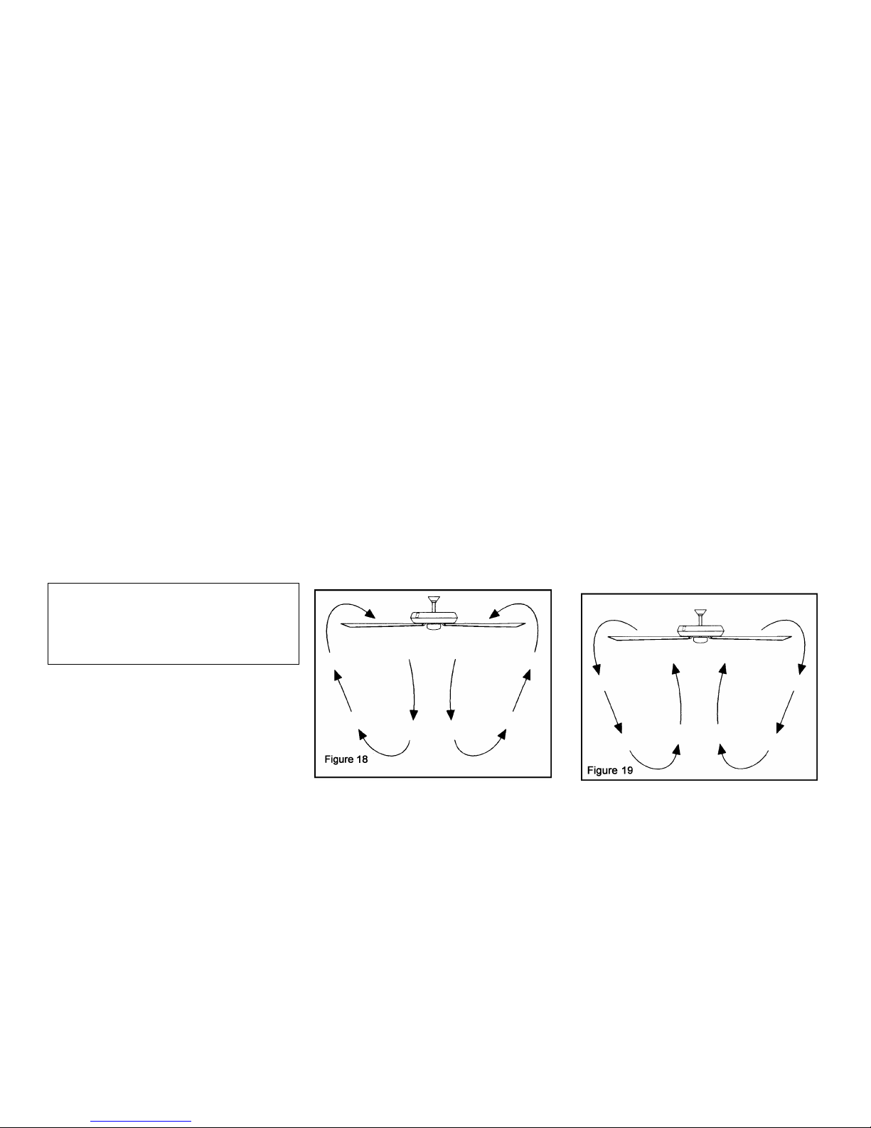
Warm weather- (Forward) A downward
air flow creates a cooling effect as shown
in Figure 18. This allows you to set your
air conditioner on a higher setting
without affecting your comfort.
Cool weather- (Reverse) An upward
airflow moves warm air off the ceiling
area as shown in Figure 19. This allows
you to set your heating unit on a lower
setting without affecting your comfort.
11.Operating You Fan
11.Operating You Fan

O
p
eratin
g
Your Remote Control 12.
Setting the Code
This unit has 16 different codecombinations.
To set the code, perform the following steps.
A. Setting the code on the transmitter:
a. Remove the battery cover from the battery
compartment in the back side of the transmitter.
b. Slide code switches to your choice of up or down
position (factory setting is all up).
B. Setting the code on the receiver:
a. Slide code switches to the same position as set on
your transmitter.
b. Re-place the battery cover on the battery compartment
of the transmitter.
CAUTION: Ceiling angle shall not exceed 45 degrees.
Remote Control Model: UC7067RYL
Installing Receiver
WARNING: To reduce the risk of fire or electric shock,
remember to disconnect power. Do not use solid state fans,
electrical wire must meet all local and national electrical code
requirement. Electrical source and fans must be 115/120 volt,
60Hz. Maximum fan motor amps: 1.0. Maximum light watts:
300-incandescent only.
A. Wire connection:
Fan Green Wire Bare Supply Wire
Black Receiver Wire (AC IN L) Black Supply Wire
White Receiver Wire(AC IN N) White Supply Wire
White receiver Wire(TO MOTOR N) White Fan Wire
Black Receiver Wire(TO MOTOR L) Black Fan Wire
Blue Receiver Wire(FOR LIGHT) Blue Light Wire
NOTE: If other fan or supply wires are different color, have
this unit installed by a licensed electrician.
B. Lay the black antenna wire on top of the receiver and slide
the receiver into the mounting plate.
Operating Transmitter
Install a 12 volt battery (included).
This remote is equipped with 16 code combinations. To
prevent possible interference from or to other remote units
such as garage door openers, car alarm or security system,
simply change the combination code but be sure that the code
on both transmitter and receiver are matched.
This device complies with part 15 of the FCC rules. Operation
is subject to the following two conditions:(1) This device may
not cause harmful interference and (2) This device must accept
any interference received, including interference that may
cause undesired operation.
Operating the fan:
●●● Key---High Speed
●● Key--Medium Speed
●Key---Low Speed
Key---Light On/Off and Dimmer
Key (inside the battery compartment in the back side of
the transmitter) -Fan Reversing Function
■ Key---Fan Off

13.Care of Your Fan
Here are some suggestions to help you
maintain your fan.
1. Because of the fan's natural
movement, some connections may
become loose. Check the support
connections, brackets, and blade
attachments twice a year. Make sure
they are secure. (It is not necessary to
remove fan from ceiling.)
2. Clean your fan periodically to
help maintain its new appearance over
the years. Do not use water when
cleaning. Use only a soft brush or
lint-free cloth to avoid scratching the
finish. The plating is sealed with a
lacquer to minimize discoloration or
tarnishing. This could damage the
motor, or the wood or possibly cause
an electrical shock.
5. You can apply a light coat of
furniture polish to the wood for
additional protection and enhanced
beauty. Cover small scratches with a
light application of shoe polish.
4. There is no need to oil your fan.
The motor has permanently lubricated
sealed ball bearings.
WARNING
MAKE SURE THE POWER IS OFF AT THE
ELECTRICAL PANEL BOX BEFORE YOU
ATTEMPT ANY REPAIRS. REFER TO THE
SECTION, "MAKING ELECTRICAL
CONNECTIONS."

Troubleshooting 14.
Problem Solution
Fan will not start.
Fan sounds noisy.
1. Check main and branch circuit fuses or breakers.
2. Check line wire connections to the fan and switch wire connections in the switch housing.
CAUTION: Make sure main power is off.
3. Check battery in the transmitter. Does the red LED light come on? Are you standing close
enough to the fan (normal range is 10-20 feet)? Are the dip switch settings the same on the
transmitter (hand unit) and receiver? REMEMBER TO TURN OFF POWER SUPPLY
BEFORE CHECKING THE DIP SWITCH SETTINGS IN RECEIVER.
1. Make sure all motor housing screws are snug.
2. Make sure the screws that attach the fan blade bracket to the motor hub are tight.
3. Make sure wire nut connections are not rattling against each other or the interior wall of the
switch housing.
CAUTION: Make sure main power is off.
4. Allow a 24-hour "breaking-in" period. Most noises associated with a new fan disappear during
this time.
5. If using the Ceiling Fan light kit, make sure the screws securing the glassware are tight. Check
that the light bulb is also secure.
6. Make sure the canopy is a short distance from the ceiling.
It should not touch the ceiling.
7. Make sure your ceiling box is secure and rubber isolator pads were used between the hanger
bracket and ceiling box.

FAN SIZE SPEED VOLTS AMPS WATTS RPM N.W. G.W. C.F.
Low 120 0.33 14 60
Med. 120 0.47 33 100
54”
High 120 0.65 78 170
38.1
Lbs
43.3
Lbs 4.45
These are approximate measures. They do not include Amps and Wattage used by the light kit.
2011 Thomasville Lighting Inc.
701 Millennium Blvd.,
Greenville, SC 29607
All Rights Reserved
15.Specifications

Garantía Limitado del Curso de la Vida
Garantía Limitado del Curso de la Vida
LOS VENTILADORES THOMASVILLE LIGHTING SE AUTORIZAN AL USUARIO DEL
EXTREMO PARA ESTAR LIBRES DE LOS DEFECTOS ELÉCTRICOS Y/O MECÁNICOS
PARA UN CURSO DE LA VIDA. LOS INTERRUPTORES CON CADENA, LOS
INTERRUPTORES DE INVERSIÓN, LOS CONDENSADORES Y LAS TERMINACIONES
METÁLICA ESTÁN GARANTIZADAS POR UN PERÍODO DE 1 AÑO. LAS PALETAS
PANDEADAS DE MADERA O PLÁSTICO NO ESTÁN CUBIERTAS POR ESTA
GARANTÍA.
EL CONSUMIDOR TIENE LA OPCIÓN DE DEVOLVER EL VENTILADOR DEFECTUOSO
PARA SU CAMBIO AL NEGOCIO DE ADQUISICIÓN DURANTE LOS 30 DÍAS
SIGUIENTES. DESPUÉS DE 30 DÍAS, EL COMPRADOR DEBE CONTACTAR
THOMASVILLE LIGHTING PARA LA REPARACIÓN O REEMPLAZO. EL CONSUMIDOR
SE HARÁ CARGO DE TODOS LOS COSTOS DE TRANSPORTE, EXPEDICIÓN Y
REINSTALACIÓN DE LOS VENTILADORES O DE LAS PARTES PARA REPARAR O
REEEMPLAZAR.
THOMASVILLE LIGHTING NO ASUMIRÁ OBLIGACIONES O RESPONSABILIAD POR
DAÑOS (INCLUYENDO INCIDENTALES O CONSIGUIENTES) CAUSADOS POR EL USO
O LA INSTALACIÓN IMPROPIA DE LA UNIDAD O DE SUS PARTES COMPONENTES, O
POR LA FALLA DEL EQUIPO DE SOPORTE NO SUMINISTRADO POR THOMASVILLE
LIGHTING. ESTA GARANTÍA ESTÁ DADA EN LUGAR DE TODAS LAS OTRAS
GARANTÍAS, SEAN ÉSTAS EXPRESAS O IMPLÍCITAS, Y ES INVÁLIDA EN CASOS
DE ABUSO, USO O MANEJO INCORRECTOS, TRATAMIENTO NEGLIGENTE, DAÑOS
OCASIONADOS POR EL TRANSPORTE, REPARACIONES NO AUTORIZADAS
(REALIZADAS O TENTATIVAS) O APLICACIÓN INUSUAL.
ALGUNOS ESTADOS NO RECONOCEN LIMITACIONES EN EL TÉRMINO DE LA
GARANTÍA IMPLICADA O LA EXCLUSIÓN O LIMITACIÓN DE LOS DAÑOS
INCIDENTALES O CONSIGUIENTES, ENTONCES LAS LIMITACIONES Y
EXCLUSIONES PRECEDENTES PUEDEN NO SER APLICABLES A UD. ESTA
GARANTÍA LE OTORGA DERECHOS ESPECÍFICOS Y UD. PUEDE TENER OTROS
DERECHOS QUE VARÍEN DE ESTADO EN ESTADO.
FechadeCompra
Lugardecompra
No. de Modelo CUL 54-TS
No.deSerie
No. de Vendedor 5523
UPC 785247128389

Reglas de Seguridad 1
Cómo Desembalar Su Ventilador 2
Cómo Instalar Su Ventilador 3
Cómo Operar Su Ventilador 11
Operarción del Control Remoto 12
Mantenimiento De Su Ventilador 13
Solución De Problemas 14
Especificaciones 15
Indice
Table of contents
Languages:
Popular Fan manuals by other brands


Bastilipo
Bastilipo Mistral instruction manual

Swegon
Swegon ADAPT Parasol b Technical manual

Panasonic
Panasonic Whisper Green FV-05VK1 installation instructions

Bryant
Bryant ERVBBLHA Series installation instructions

Monte Carlo Fan Company
Monte Carlo Fan Company AC-552 Owner's guide and installation manual

Gallet
Gallet Blizzard VEN31 instruction manual