Thommen AC32 User manual


REVUETHOMMENAG
CH-4437 Waldenburg
AC32 DIGITAL AIR DATA COMPUTER
INSTALLATION MANUAL
Page 2 of 105
04-Jan-2011
Document No. AC-INST-500
Revision 2.1
REVISION HISTORY
REVISION
DESCRIPTION
ISSUE DATE
INITIAL
CHECKED
1.0
INITIAL RELEASE
30th Aug, 2004
AG
RW
1.1
Appendix VI - Equipment Dimensions
: Compact Case added.
Appendix VII - Identification Plates
added.
Note 1 added in Section I –1-A
In Section III-1-C
Lightning Induced Transient
Susceptibility- RTCA/DO-160D
Section 22.0 Cat. [A3E3] changed to
RTCA/DO-160D Section 22.0 Cat.
[A3J33]
18th Jan, 2005
AG
RW
1.2
Appendix - Software Version SW 2.10
features added
23rd Nov, 2005
AG
RW
1.3
NOTE 2 added in Sec IV-1-E2
9th Dec, 2005
AG
RW
1.4
Appendix - Software Version SW 2.11
features added
Section III-1-C Environmental
Qualification updated
23rd May, 2006
AG
RW
1.5
Appendix X - Software Version SW
2.31 feature added
Appendix XI –Outputs added
Mating Electrical Connector MS
Number introduced on page 40
Total Air Temperature (TAT)
Calibration Table: Resistance Pt 100
added in Appendix V
17th Jan, 2008
AF
RW
1.6
Appendix VII –Env. Cat. in
Identification Plate added
Appendix XII –SW Version 2.40
feature added
Appendix XIII –SW Version 2.50/2.51
features added
Document Formats changed
12th Mar, 2008
RW
MB
1.7
Appendix XIII –SW Version 2.51
label 242 resolution corrected
23-May-2008
RW
MB
1.8
Appendix XIV –SW Version 2.60
features added
20-April-2009
AF
RW
1.9
formal changes throughout the
document
TAT probe interface updated
Discrete I/O functions updated
Appendix I Failure Codes, Failure
14-Oct-2009
AF
RW

REVUETHOMMENAG
CH-4437 Waldenburg
AC32 DIGITAL AIR DATA COMPUTER
INSTALLATION MANUAL
Page 3 of 105
04-Jan-2011
Document No. AC-INST-500
Revision 2.1
REVISION
DESCRIPTION
ISSUE DATE
INITIAL
CHECKED
class and BIT Matrix added
Appendix III Airspeed calibration table
extended
Appendix IV Mach no. calibration
table extended
Appendix V TAT/OAT calibration table
updated
Appendix XI „IAS damping‟and
„Calculation of impact pressure qci‟
added
Appendix XV –SW Version 2.70
features added
2.0
Change of logical state of Bit 13 label
270 for selected SW versions
27-May-2010
MB
RW
2.1
G.2: ARINC 429 transmit channel bus
load specified.
Appendix XVI –HW version 2.21 /
MOD 01A change for improved
ARINC 429 bus load.
04-Jan-2011
RW
AF
CAUTION:
Before attempting any installation activities on the equipment covered in this manual, verify that
you have complete and up-to-date publications by referring to the applicable manual revisions and
service bulletin indices.

REVUETHOMMENAG
CH-4437 Waldenburg
AC32 DIGITAL AIR DATA COMPUTER
INSTALLATION MANUAL
Page 4 of 105
04-Jan-2011
Document No. AC-INST-500
Revision 2.1
SERVICE BULLETIN INDICES
SB No.
SERVICE BULLETIN
SUBJECT
EDITION / REVISION
NUMBER
Date
AD32/AC32/01
Hardware and Software
Modification
Initial Release
30th August, 2004
AC32/04
Hardware Modification
Initial Release
02-Dec-2010

REVUETHOMMENAG
CH-4437 Waldenburg
AC32 DIGITAL AIR DATA COMPUTER
INSTALLATION MANUAL
Page 5 of 105
04-Jan-2011
Document No. AC-INST-500
Revision 2.1
Table of Contents Page
REVISION HISTORY..........................................................................................................................................2
SERVICE BULLETIN INDICES..........................................................................................................................4
SECTION I..........................................................................................................................................................9
Introduction................................................................................................................................. 9
A. Purpose of the manual ........................................................................................................ 9
B. Equipment Specification...................................................................................................... 9
C. Technical Specification...................................................................................................... 13
D. Equipment Dimensions ..................................................................................................... 14
E. Interface Block diagram..................................................................................................... 16
SECTION II.......................................................................................................................................................17
General Information................................................................................................................... 17
Description................................................................................................................................ 17
A. Equipment Description ...................................................................................................... 17
Operations ................................................................................................................................ 18
A. Theory of Operations......................................................................................................... 18
B. Operating Modes............................................................................................................... 22
Testing...................................................................................................................................... 23
A. Built-in-Test....................................................................................................................... 23
B. Failure Modes.................................................................................................................... 24
SECTION III......................................................................................................................................................26
Approvals.................................................................................................................................. 26
A. General ............................................................................................................................. 26
B. Instructions for Continued Airworthiness............................................................................ 26
C. Environmental Qualification............................................................................................... 27
SECTION IV .....................................................................................................................................................31
Installation................................................................................................................................. 31
A. General ............................................................................................................................. 31
B. Unpacking and Inspecting ................................................................................................. 31
C. Pre and Post Installation Check ........................................................................................ 31
D. Electrical Interface............................................................................................................. 31
E. Electrical connector........................................................................................................... 35
G. Digital Data Interfaces....................................................................................................... 43
G.3.1 Label 203 (Pressure Altitude)....................................................................................... 46
G.3.12 Label 217 (Indicated static pressure).......................................................................... 57
G.3.20 Label 320 (Magnetic Heading) ................................................................................... 65
I. ICAO Encoded Altitude Output ........................................................................................... 71
J. RS-232 Serial Interface...................................................................................................... 71

REVUETHOMMENAG
CH-4437 Waldenburg
AC32 DIGITAL AIR DATA COMPUTER
INSTALLATION MANUAL
Page 6 of 105
04-Jan-2011
Document No. AC-INST-500
Revision 2.1
SECTION V ......................................................................................................................................................72
1. Trouble shooting ................................................................................................................... 72
2. Maintenance.......................................................................................................................... 73
A. Recalibration Interval............................................................................................................ 73
APPENDICES...................................................................................................................................................74
Appendix I................................................................................................................................. 74
Failure Codes........................................................................................................................ 74
Appendix II................................................................................................................................ 78
Altimeter Calibration Table..................................................................................................... 78
Appendix III............................................................................................................................... 79
Airspeed Calibration Table..................................................................................................... 79
Appendix IV............................................................................................................................... 80
MACH Number Calibration Table........................................................................................... 80
Appendix V................................................................................................................................ 82
Total Air Temperature (TAT) / Outside Air Temperature (OAT) Calibration Table.................. 82
Appendix VI............................................................................................................................... 83
Equipment Dimensions : Compact Case................................................................................ 83
Appendix VII.............................................................................................................................. 85
Identification Plates................................................................................................................ 85
Appendix VIII............................................................................................................................. 86
Software Version SW 2.10:.................................................................................................... 86
Appendix IX............................................................................................................................... 90
Software Version SW 2.11:.................................................................................................... 90
Appendix X................................................................................................................................ 91
Software Version SW 2.41:.................................................................................................... 91
Appendix XI............................................................................................................................... 92
Software Version 2.30:........................................................................................................... 92
Appendix XII.............................................................................................................................. 94
Software Version SW 2.40:.................................................................................................... 94
Appendix XIII............................................................................................................................. 95
Software Version SW 2.50:.................................................................................................... 95
Software Version SW 2.51:.................................................................................................... 96
Appendix XIV ............................................................................................................................ 97
Software Version SW 2.60:.................................................................................................... 97
Appendix XV ............................................................................................................................. 99
Software Version SW 2.70:.................................................................................................... 99

REVUETHOMMENAG
CH-4437 Waldenburg
AC32 DIGITAL AIR DATA COMPUTER
INSTALLATION MANUAL
Page 7 of 105
04-Jan-2011
Document No. AC-INST-500
Revision 2.1
Multiple configurable VMO ...................................................................................................... 104
Appendix XVI .......................................................................................................................... 105
Hardware Version 2.21 / MOD 01A:..................................................................................... 105
List of Figures Page
Figure 1: Equipment Front and Rear View........................................................................................ 14
Figure 2: Equipment Side and Top View........................................................................................... 15
Figure 3: AC32 Block Diagram.......................................................................................................... 16
Figure 4: Primary Power Fail............................................................................................................. 25
Figure 5: AC32 Harness Shielding.................................................................................................... 33
Figure 6: AC32 Primary Power Fail................................................................................................... 34
Figure 7: Wiring Diagram.................................................................................................................. 39
Figure 8: Digital Air Data Computer Communication......................................................................... 40
List of Tables Page
Table 1: Type Identification............................................................................................................... 11
Table 2: Installation Kit...................................................................................................................... 12
Table 3: Technical Specification ....................................................................................................... 13
Table 4: ARINC429 Labels ............................................................................................................... 20
Table 5: Operating ranges, limiting values and tolerances................................................................ 21
Table 6: Fault code handling............................................................................................................. 24
Table 7: Environmental Qualification................................................................................................. 29
Table 8: Pin Assignments................................................................................................................. 37
Table 9: Resistance Pt 500............................................................................................................... 41
Table 10: TAT Signals ...................................................................................................................... 41
Table 11: ARINC 429 Labels ............................................................................................................ 43
Table 12: ARINC 429 I/O Transfer labels.......................................................................................... 45
Table 13: ARINC 429 I/O Transfer for Baro Correction..................................................................... 45
Table 14: ARINC 429 Labels Format................................................................................................ 45
Table 14: Discrete Inputs.................................................................................................................. 70
Table 15: Discrete Outputs ............................................................................................................... 71
Table 16: Trouble Shooting Procedures............................................................................................ 72

REVUETHOMMENAG
CH-4437 Waldenburg
AC32 DIGITAL AIR DATA COMPUTER
INSTALLATION MANUAL
Page 8 of 105
04-Jan-2011
Document No. AC-INST-500
Revision 2.1
List of Abbreviations and Acronyms
Abbreviation
Description
A/C
Aircraft
Abs
Absolute
ADC
Air Data Computer
ARINC
Aeronautical Radio Inc.
ASCII
American Standard Code for Information Interchange
BIT
Built In Test
DC
Direct Current
Diff
Differential
EMI
Electro Magnetic Interference
FAA
Federal Aviation Administration (USA)
FAR
Federal Aviation Regulation
FI
Flight Instruments
FIG
Figure
HW
Hardware
ICAO
International Civil Aviation Organization
IF
Interface
N.A.
Not applicable
NC
Not Connected
REV
Revision
RTCA
Radio Technical Commission for Aeronautics
RTW
REVUE THOMMEN AG, Waldenburg
RVSM
Reduced Vertical Separation Minima
SSEC
Static Source Error Correction
SW
Software
TBD
To Be Defined
TSO
Technical Standard Order
HIRF
High Intensity Radiated Field

REVUETHOMMENAG
CH-4437 Waldenburg
AC32 DIGITAL AIR DATA COMPUTER
INSTALLATION MANUAL
Page 9 of 105
04-Jan-2011
Document No. AC-INST-500
Revision 2.1
SECTION I
Introduction
A. Purpose of the manual
This manual provides the specifications, installation instructions and system maintenance in details
for the REVUE THOMMEN AC32 Digital Air Data Computer equipment. This manual also defines
interface design requirements including mechanical and electrical characteristics for REVUE
THOMMEN AC32. The Interface Control Document (ICD) information is also covered in detail in this
manual.
The description and procedures are covered in different topics as shown in the Table of Contents,
and the troubleshooting procedures are given under sections to identify the fault and failure
conditions of the equipment with the interface systems.
The contents of this manual have been verified by actual performance of the equipment prior to
distribution of printed copies.
The procedures in this manual are to be performed by qualified personnel familiar with REVUE
THOMMEN AC32 Digital Air Data Computer Equipment.
Note 1 : This manual replaces the AC32 Interface Control Document (Doc no. AD-ICD-530).
B. Equipment Specification
B.1 Applicable Documents
The following column shows the list of relevant applicable documents which forms the basis of
approvals of the AC32 Digital Air Data Computer.
STANDARDS
TSO-C106 Air Data Computer
SAE AS8002 Air Data Computer Minimum Performance Standards
ARINC 706-4 Mark 5 Subsonic Air Data System
ARINC 607-3 Design Guidance for Avionic Equipment
ARINC 429 Mark 33 Digital Information Transfer System (DITS)
TSO-C88a Automatic Pressure Altitude Reporting Code Generating Equipment
SAE AS8003 Minimum Performance Standard for Automatic Pressure Altitude Reporting
Code Generating Equipment
MILITARY
MS33649 Bosses, Fluid Connection - Internal Straight Thread
MIL-C-14806 Coating, reflection reducing, for instrument cover glasses and lighting wedges

REVUETHOMMENAG
CH-4437 Waldenburg
AC32 DIGITAL AIR DATA COMPUTER
INSTALLATION MANUAL
Page 10 of 105
04-Jan-2011
Document No. AC-INST-500
Revision 2.1
SPECIFICATIONS
AC-SPE-500 AC32 Specification Digital Air Data Computer
ADAC-SWR-420 ADAC Software Requirements
Limitations Limited to manufacturer specifications of the digital input bus and to the
applicable configuration and Mod status.
COMMERCIAL
RTCA/DO-160D Environmental Conditions and Test Procedures for Airborne Equipment
with Change, 1 Change 2 and Change 3
ED-12B Software Considerations in Airborne Systems and Equipment Certification
RTCA/DO-178B
ED-14D Environmental Conditions and Test Procedures for Airborne Equipment
RTCA/DO-160D
ED-80 ED-80 / RTCA/DO-254 Design Assurance Guidance for Airborne Electronic
RTCA/DO-254 Hardware
OTHER PUBLICATIONS
- None

REVUETHOMMENAG
CH-4437 Waldenburg
AC32 DIGITAL AIR DATA COMPUTER
INSTALLATION MANUAL
Page 11 of 105
04-Jan-2011
Document No. AC-INST-500
Revision 2.1
B.2 Identification
B.2.1 Type Identification
Type : AC32.10.21.11.AE (For Sample)
AC32
Digital Air Data Computer
. 1
- 1000…53000 ft / 0/20…200 Knots
.-0
Standard Function
.2
Power Supply 28 VDC (< 7 W)
.-1
ARINC 429 serial data bus
(High speed mode)
.1
With TAT probe input
500 Ohm acc. to ARINC 706-4
.-1
With ICAO encoding output
.AE
See spec. code as below mentioned
Table 1: Type Identification
AE spec. Code:-Acc. to TSO-C106, TSO-C88a
-Pneumatic Ports
“S” 1 / 2” - 20UNJF-3B (MS 33649-5)
“P” 7 / 16” - 20UNJF-3B (MS 33649-5)
-Electrical connector 55- Pin
MS 3112E-22-55P (MIL-C-26482 Series 1)
-Warning flag valid signal 28 VDC
-RS-232 Maintenance Interface
-Case alodine yellow
Mod Number: MOD00A (For sample)
Configuration Number: ID 0201 (For sample)

REVUETHOMMENAG
CH-4437 Waldenburg
AC32 DIGITAL AIR DATA COMPUTER
INSTALLATION MANUAL
Page 12 of 105
04-Jan-2011
Document No. AC-INST-500
Revision 2.1
B.2.2 Identification Plate
The Identification/Name plate is attached in the equipment case of AC32 Digital Air Data Computer
externally. The sample of Identification/Name plate of AC32 Digital Air Data Computer equipment is
shown below:
Identification Plate: AC32.10.21.11.AE, MOD00A, Config. ID 0201
REVUE THOMMEN AG
CH-4437 WALDENBURG
DIGITAL AIR DATA COMPUTERWITH ENCODER
CERTIFIED TSO-C106 / TSO-C88a
RTCA/ DO 178B Level A / DO-160D
PART/TYPE NO AC32.10.21.11.AE
CONFIGURATION ID 0201
SER NO 0000000
MOD
00
01
02
03
04
05
06
07
08
09
A
B
C
D
E
F
G
H
I
J
RANGES -1,000 ... 53,000 FEET
0 / 40 ... 450 KNOTS
0.200 … 0.999 MACH
MFR DATE month / year
SWISS MADE PHONE + 41 61 965 22 22 FAX + 41 61 961 81 71
B.3 Installation Kit
Part Number
Quantity
Description
AC32.XX.XX.XX.XX
1
AC32 Digital Air Data Computer
AC-INST-500
1
AC32 Installation Manual
AC-DDP-XXX
1
Declaration of Design and Performance
Document
Table 2: Installation Kit
NOTE: As ordered by the Installer.

REVUETHOMMENAG
CH-4437 Waldenburg
AC32 DIGITAL AIR DATA COMPUTER
INSTALLATION MANUAL
Page 13 of 105
04-Jan-2011
Document No. AC-INST-500
Revision 2.1
C. Technical Specification
Characteristics
Specifications
Primary Power
28 VDC
During startup
max. 7 W
Normal operation
max. 5 W
max. current draw
0.7 A
Emergency Power
28 VDC
Weight *
1 kg (2.2 lbs)
Physical Dimension
Height
109 mm (4.29 in)
Width
110 mm (4.3 in)
Length
194.5 mm (7.657 in)
Maintenance Requirements
On Condition
*Weight, excluding connectors, pneumatic adaptors and fixing screws
Table 3: Technical Specification
REVUETHOMMENAG
CH-4437 Waldenburg
AC32 DIGITAL AIR DATA COMPUTER
INSTALLATION MANUAL
Page 14 of 105
04-Jan-2011
Document No. AC-INST-500
Revision 2.1
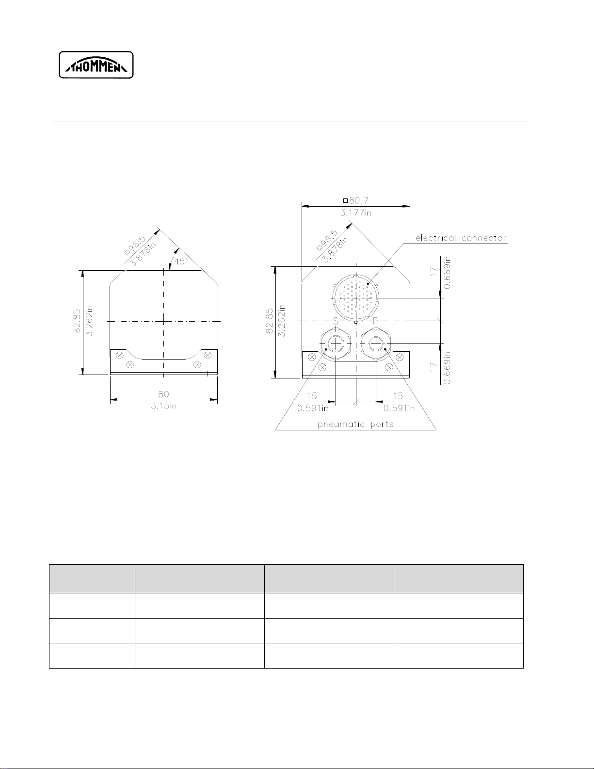
D. Equipment Dimensions
Equipment Dimensions :
Figure 1: Equipment Front and Rear View
NOTE: The dimensions are in millimeters or inches
NOTE: Not to scale
Pneumatic Pressure Ports
Mechanical
Pressure range
Over pressure
capability
Static Port ”S”
(standard)
1/2“-20UNJF-3B
(MS33649-5)
25 … 1100 mbar abs
1500 mbar abs
Static Port ”S”
(optional)
9/16“-18UNJF-3B
(MS33649-6)
25 … 1100 mbar abs
1500 mbar abs
Pitot Port “P”
7/16“-20UNJF-3B
(MS33649-4)
100 … 1500 mbar abs
3000 mbar abs

REVUETHOMMENAG
CH-4437 Waldenburg
AC32 DIGITAL AIR DATA COMPUTER
INSTALLATION MANUAL
Page 15 of 105
04-Jan-2011
Document No. AC-INST-500
Revision 2.1
Figure 2: Equipment Side and Top View

REVUETHOMMENAG
CH-4437 Waldenburg
AC32 DIGITAL AIR DATA COMPUTER
INSTALLATION MANUAL
Page 16 of 105
04-Jan-2011
Document No. AC-INST-500
Revision 2.1
E. Interface Block diagram
Static Port S
ICAO Encoded
OUT
Primary Power
Emergency Power
Warning Flag
Valid OUT
RS232
Power Supply
CPU
Connector
ENCODER
Static
Pressure
Sensor
Pitot Port P Pitot
Pressure
Sensor
TAT Probe
AC32 Digital Air Data Computer
Receive Channels
Transmit Channels
ARINC 429
ENCODER
RS232
Maintenance IF
A/D-C
Discrete Inputs
Discrete Outputs
ENCODER
Figure 3: AC32 Block Diagram

REVUETHOMMENAG
CH-4437 Waldenburg
AC32 DIGITAL AIR DATA COMPUTER
INSTALLATION MANUAL
Page 17 of 105
04-Jan-2011
Document No. AC-INST-500
Revision 2.1
SECTION II
General Information
This Section provides the description required to understand the functionality of AC32 Digital Air Data
Computer equipment. Refer to the following paragraph for the brief description of the instrument.
Description
A. Equipment Description
The AC32 Digital Air Data Computer belongs to the Solid State Flight equipment Family of REVUE
THOMMEN AG. The implementation of the AC32 Digital Air Data Computer measures barometric
altitude, airspeed and temperature in the atmosphere. It has integrated solid-state pressure sensors
for static and pitot pressure. The AC32 is RVSM compliant and provides up to 2 x 16 SSEC curves.
This specification covers a Digital Air Data Computer with
- Primary Altitude computation
- Airspeed and MACH computation
- ARINC429 Interface
- Encoded altitude output (optional)
- TAT probe input (optional)
The computed air data parameters are transmitted by the ARINC 429 serial data bus interface. Two
transmit channels and two receive channels are available, with which also the baro correction is
carried out. An ICAO encoded altitude output is also available as an option.
The AC32 is designed modular and hence very easy to maintain by RS-232 maintenance interface
serial data. Its power supply is available for 28 VDC. The low power consumption of less than 7 Watts
and its low weight of only 1000 grams (2.2 lbs) have been optimized for applications in state-of-the-art
avionics.
The THOMMEN AC32 Digital Air Data Computer can be configured for different applications as per
the interface requirements. Therefore its application range reaches from Business Aviation up to
Regional Aircraft, Transporters and Helicopters.
The THOMMEN AC32 Digital Air Data Computer meets or exceeds the requirements of the FAA
technical standard order TSO-C106 and TSO-C88a accuracy requirements.
The AC32 Digital Air Data Computer communicates with flight Displays that show the data of the
AC32 Digital Air Data Computer and allows the Baro correction. The communication uses the ARINC
429 serial data bus.
This AC32 Digital ADC does not support the analog interfaces.

REVUETHOMMENAG
CH-4437 Waldenburg
AC32 DIGITAL AIR DATA COMPUTER
INSTALLATION MANUAL
Page 18 of 105
04-Jan-2011
Document No. AC-INST-500
Revision 2.1
Operations
Caution:
The AC32 Digital Air Data Computer equipment has been designed to exhibit a very high
degree of functional integrity. However it is possible that erroneous operation could occur
without fault. It is the responsibility of the operator to detect such an occurrence by means of
cross check with redundant or correlated information available in the cockpit.
A. Theory of Operations
This part of the manual is to familiarize the reader with the AC32 Digital Air Data Computer
equipment and to give a brief theory of operation.
A.1 Power Supply
The AC32 Digital Air Data Computer is designed to be supplied by a 28 VDC power supply in
accordance with RTCA/DO-160D Section 16.0 Category Z.The equipment does not require more
than 7 W for normal operation.
An optional secondary 28 VDC emergency power supply input, drawn from emergency bus should be
provided to continue operation, in case of primary power supply failure.
NOTE: In case of power fail or switching off the equipment‟s power supply the AC32 sets the
warning flag valid output signal to LO (WFVOUTS).
A.2 Micro Controller
The Micro Controller is a flash type micro controller built around CPU (Central Processing Unit) board
of the instrument. The CPU has an internal 32-bit architecture which is provided with sixteen 16-bit
general registers and a concise, optimised instruction is designed for high-speed operation. The CPU
can also address a 16-Mbyte linear address space.
The operating voltage and the port power voltage of the Micro controller is +3.3 VDC. A crystal
oscillator of 4 MHz is connected to the micro controller and an internal clock generator produces the
system clock of 16 MHz.
The data and address bus from the Micro controller is also used for the two functions used outside
the CPU. This is for the communication with both the ARINC 429 and to the latches for the ICAO
encoded output of the instrument.

REVUETHOMMENAG
CH-4437 Waldenburg
AC32 DIGITAL AIR DATA COMPUTER
INSTALLATION MANUAL
Page 19 of 105
04-Jan-2011
Document No. AC-INST-500
Revision 2.1
A.3 ARINC 429 Interface
The ARINC 429 module in AC32 Digital Air Data Computer supports the ARINC-I/O interface and the
bus interface to the CPU.
The ARINC 429 offers the following main features:
-Two transmitter and two receiver ports
-ARINC Low-Rate & High-Rate support with appropriate slew-rate control
-Multiple local loop-back facilities for improved BIT
-Lightning Induced Transients Suppression compliant with RTCA/DO-160D
-Hardening against aircraft wiring errors on ARINC inputs
Digital Data Standards are acc. to ARINC 429 Mark 33 DITS and ARINC 706-4 Mark 5 SADS /
equipment ID 006
The following table shows the ARINC labels for various signals used for AC32 Digital Air Data
Computer:
Label
Signal Name
Operational
Range 1)
Unit
Resolution
Update Rate
per s
203
Pressure altitude
(1013.25 mbar)
-1000 ..+53,000
feet
1
16
204
Baro corrected altitude
#1
-1000 ..+53,000
feet
1
16
220
Baro corrected altitude
#2
-1000 ..+53,000
feet
1
16
205
Mach number
0.200 .. 0.999
MACH
0.0000625 knot
8
206
Computed airspeed
0 / 40 .. 450
knots
0.0625
8
207
Maximum Allowable
Airspeed
150 .. 450
knots
0.25
8
210
True airspeed
0 / 100 .. 599
knots
0.0625
8
211
Total air temperature
-60 .. +99
°C
0.25
2
212
Altitude Rate
0 .. 20,000
ft/min.
16
16
213
Static air temperature
-99 .. +60
°C
0.25
2
215
Impact Pressure
0 .. 372.5
mbar
0.03125
8
217
Static Pressure
0 .. 64
inHg
0.001
8
234
Baro Correction mb #1
700 .. 1050
mbar
0.1
8
235
Baro Correction inHg #1
20.67 .. 31.00
inHg
0.001
8
236
Baro Correction mb #2
700 .. 1050
mbar
0.1
8
237
Baro Correction inHg #2
20.67 .. 31.00
inHg
0.001
8
242
Total Pressure
25 .. 2048
mbar
0.03125
8
270
Discrete Word #1
--
--
--
2

REVUETHOMMENAG
CH-4437 Waldenburg
AC32 DIGITAL AIR DATA COMPUTER
INSTALLATION MANUAL
Page 20 of 105
04-Jan-2011
Document No. AC-INST-500
Revision 2.1
Label
Signal Name
Operational
Range 1)
Unit
Resolution
Update Rate
per s
271
Discrete Word #2
--
--
--
2
350
Maintenance Word #1
--
--
--
2
351
Maintenance Word #2
--
--
--
2
353
Indicated airspeed
0 / 40 .. 450
knots
0.0625
8
377
Equipment Identifier
006
--
--
16
Table 4: ARINC429 Labels
A.4 RS-232 Serial Interface
The AC32 Digital Air Data Computer has a RS-232 interface for maintenance and calibration
purposes only. This interface is not accessible for normal operation in the aircraft.
The RS-232 Interface is provided for calibration and maintenance causes has the following
transmission parameters:
Baud Rate...…... 9600 kBit/s
Start Bits...…..... 1
Data Bits....……. 8
Stop Bits.....…... 1
Parity...........…... None
A.5 Configuration Identification
The configuration identification defines a specific equipment configuration parameterized by the
individual parameter lists for each AC32 equipment, which in turn explains the different parameter
requested by the installer. So for every new AC32 equipment different Configuration ID number is
designated.
CONFIGURATION ID 5001 (SAMPLE)
NOTE: Refer to Technical Checklist for Configuration ID (Identification) designation.
Table of contents


