THOMSON ITC222 Installation guide

ITC222
CONVERGENCE & GEOMETRY
1
0
1
0
10
1
0
1
1
0
1
0
1
0
1
0
1
0
1
0
1
0
1
0
1
0
10
10
01
0
1
RED OUTPUT
194V
TP50
TO
E8
RED BIAS
<21-B>
E5003
E5007
TO
E7
GRN BIAS
0
1
1
0
0
0
01 1
10
VERTICAL
1
1
1
0
TP24
TECHNICAL TRAINING 0
1
1
0
0
0
1
1
0
10
1
1
0
0
0
1
1
0
1


FOREWORD
This publication is intended to aid the technician in servicing the ITC222 television chassis and is
directed at convergence and geometry procedures Although some theory is involved, the manual
concentrates on correct adjustment and alignment of geometry and convergence after an SSB
module replacement or after other repairs that may require full or partial geometry or convergence
alignment. It is designed to assist the technician to become more familiar with convergence and
autoconvergence operation, increase confidence and improve overall efficiency in servicing the
product.
Note: This publication is intended for use only as a training aid. It is not meant to replace service
data. Thomson Service Data for these instruments contain specific information about parts, safety
and alignment procedures and must be consulted before performing any service. The information
inthismanualisasaccurateaspossibleatthetimeofpublication. Circuitdesignsanddrawingsare
subject to change without notice.
SAFETY INFORMATION CAUTION
Safety information is contained in the appropriate Thomson Service Data. All product safety
requirements must be complied with prior to returning the instrument to the consumer. Servicers
who defeat safety features or fail to perform safety checks may be liable for any resulting damages
and may expose themselves and others to possible injury.
All integrated circuits, all surface mounted devices, and many other
semiconductors are electrostatically sensitive and therefore require special
handling techniques.
Prepared by
Thomson, Inc for TTE Technology, Inc.
Technical Training Department, INH905
PO Box 1976
Indianapolis, Indiana 46206 U.S.A.
RED OUTPUT
194V
TP50
TO
E8
RED BIAS
<21-B>
E5003
E5007
TO
E7
GRN BIAS
VERTICAL
First Edition 0516 - First Printing
Copyright 2005 Thomson, Inc.
Trademark(s)®Registered Marca(s) Registrada(s)
RCA and the RCA Logos are trademarks of THOMSON
S.A. used under license to TTE Corporation
Printed in U.S.A.

ITC222 Convergence & Geometry
PUBLICATION OVERVIEW
This publication is intended to detail procedures for returning the convergence of an ITC222
instrument to manufacturing specifications and assuring the performance of Autoconvergence.
Procedures to do so begin the manual. Informational and tutorial sections are included only as
Appendix items.
The manual details convergence procedures and steps required to perform them. It is arranged by
procedures and listed in the order they should be performed. Typically these procedures depend
on the individual repair issue. Begin with the Overview, first determining what repairs are required,
then proceed through the manual as it is written. Geometry is critical to convergence. Care should
be taken to understand how geometry affects convergence. If at all possible geometry should not
be disturbed especially if Sensor Calibration runs successfully.
While the procedures given in the main Overview may look simple do not mistake the complexity!
Alignments are sensitive and interactive. Make certain it is understood which procedures are
required and leave other alignments alone. Changing alignments that do not need to be done will
always complicate the procedures required.
Appendix A, Chipper Check, fully explains how to use Chipper Check to transfer existing
convergence EEPROM files to a replacement SSB module. Appendix B, Field Service Menu,
documents how to use the Field Service Menu for those technicians not yet familiar with its
operation. Also included in the Appendix are tables for screen size dimensions and decimal to
fraction conversions.
GENERAL INFORMATION
This training material assumes a knowledge of the current Thomson television chassis ITC222.
The material has been prepared using general reference to geometry and convergence operation
with specific reference to the ITC222. Standard procedures and operation may change over time
so in all cases Electronic Service Data for the instrument should be consulted for the most accurate
component values and voltages.
EEPROM’s or Electrically Erasable Programmable Read Only Memory, are sometimes referred
to as NVM’s or NonVolatile Memory devices. They are the same device simply called by different
names.
Chipper Check© is Thomson, Inc PC based diagnostic and alignment system.

Contents
FOREWORD ...................................................................................................................................... 3
PUBLICATION OVERVIEW .......................................................................................................................... 4
INTRODUCTION ........................................................................................................................................ 6
CRT REPLACEMENT................................................................................................................................7
SSB MODULE REPLACEMENT .................................................................................................................. 7
CONSUMER COMPLAINTS.......................................................................................................................... 8
AUTOCONVERGENCE FAILURE .................................................................................................................. 9
CONVERGENCE PATTERN ........................................................................................................................ 11
Geometry ..................................................................................... 12
CENTERING RING ADJUSTMENT .............................................................................................................. 14
GEOMETRY ALIGNMENT ......................................................................................................................... 16
GEOMETRY TEMPLATES.......................................................................................................................... 21
Convergence................................................................................ 22
MANUAL CONVERGENCE PROCEDURES.................................................................................................... 22
REMOTE CONTROL BUTTON ASSIGNMENTS .............................................................................................. 22
CONVERGENCE TEMPLATE DESIGN ......................................................................................................... 23
STRING CALCULATIONS .......................................................................................................................... 24
LEVEL 2 CONVERGENCE ALIGNMENT ...................................................................................................... 25
LEVEL 3 CONVERGENCE ALIGNMENT ...................................................................................................... 26
Hints & Tricks............................................................................. 29
Appendix A, Chipper Check...................................................... 32
SSB MODULE REPLACEMENT ................................................................................................................ 33
IFORIGINAL SSB EEPROM CAN BE READ .......................................................................................... 33
IFORIGINAL SSB EEPROM CAN NOT BE READ.................................................................................. 37
Appendix B, Field Service Menu............................................... 38
FIELD SERVICE MODE REMOTE CONTROL BUTTON FUNCTIONS............................................................... 39
CONVERGENCE ERROR CODES................................................................................................................ 41
EVENT HISTORY .................................................................................................................................... 42
Appendix C, Screen Dimensions & Mylar Pattern.................. 48
Appendix D, Decimal to Fraction Conversion Table............... 49
SUMMARY ............................................................................................................................................. 50

ITC222 Geometry & Convergence Procedures 6
INTRODUCTION
Geometry and convergence for the ITC222 are more interactive than previous chassis designs. If
geometry is not correct or too far from nominal settings, even though geometry and convergence
both look acceptable, autoconvergence may not operate. While it may be tempting for the technician
to return the set to the consumer with both agreeing autoconvergence will not work, it is not a
recommended or endorsed completion to a repair.
The purpose of this manual is to show the interaction of geometry and convergence and how it
affects screen geometry, sensor location (sensor calibration) and autoconvergence. Autoconvergence
and manual convergence must be considered separate processes to be understood. Convergence is
digital and follows a similar process done in previous years. Atechnician must manually converge
the instrument using digital convergence. Autoconvergence is the process of determining where
manufacturing (or the technician) manually aligned convergence for acceptable performance, then
automatically return it to that alignment appearance when necessary.
It also must be understood that Geometry is controlled globally via the main deflection yokes
using individual adjustments in the Geometry menu. Geometry controls all three colors at the
same time in the same way. Convergence is independent of geometry being controlled and adjusted
by individual convergence yokes on each of the three CRT’s. But if Geometry is misadjusted
convergence may not have enough power to overcome it and proper convergence would be in
jeopardy.
There are two steps to the Autoconvergence routine; Sensor Calibration and Autoconvergence.
When the “Sensor Location” routine is run, convergence is set to a “neutral” state and the sensor
location blocks are influenced more by geometry. So if geometry is too far off, sensor location
(calibration) will fail. If sensor calibration fails, autoconvergence will also fail.
It is also possible for geometry to be misadjusted just far enough to allow sensor location to complete
yet proper convergence of all three CRT’s may not be possible because the convergence amplifiers
are railed trying to overcome the geometry yokes in order to correct the alignment points. The
correct geometry alignment is one that puts geometry in more of a nominal state allowing
convergence the greatest range.
This manual is arranged so the Geometry and Convergence procedures appear in order. However
that is not necessarily how they should be done, nor does every detail of each procedure have to be
done. Which procedures and details are required for each repair depend more on the situation.
The answer to the following questions have considerable influence over which procedures must be
used and how critical each is.
1.) Is convergence being done as the result of one or more CRT replacements?
2.) Is convergence needed after replacement of an SSB module?
3.) Is convergence required as the result of a consumer complaint?
a.) Misconvergence, or
b.) Autoconvergence routine not functioning
The remainder of the manual is based on answers to these questions.

ITC222 Geometry & Convergence Procedures
7
CRT REPLACEMENT
If one or more CRT’s have been replaced, always spend time realigning the yoke and centering
rings of the replacement(s) to existing CRT’s. Do not touch geometry and do not adjust the
convergence alignments of the CRT(s) not replaced. Centering and size are the two most important
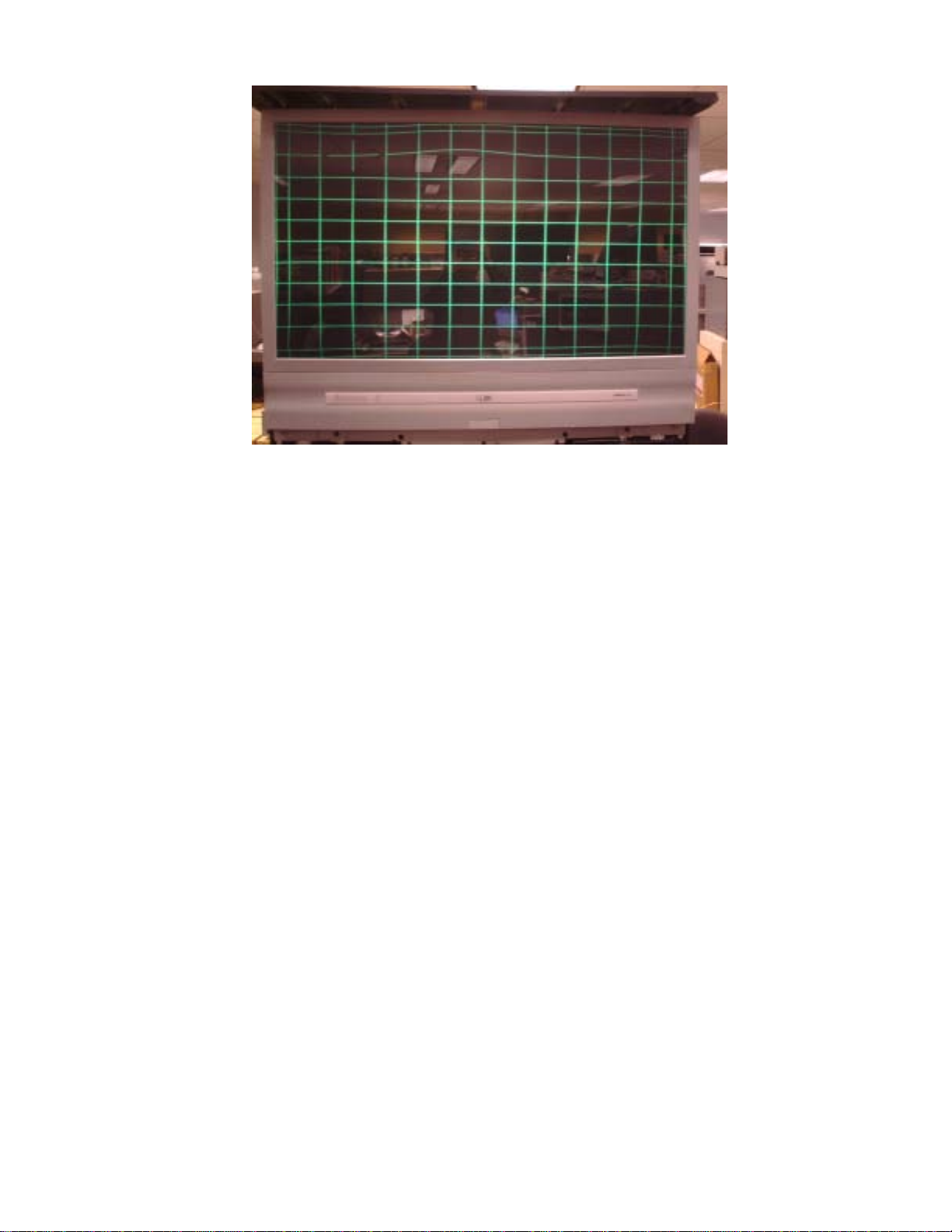
mechanical alignments. Two video patterns are required; a full crosshatch pattern with known
horizontal and vertical centerlines and the internal convergence pattern. The results of these
procedures is to make certain the center crosshair lines of the replacement CRT are on top of the
existing CRT patterns and the raster is the same size and orientation.
The procedures for CRT replacement are:
1. Once the CRT has been replaced, place the video pattern with full width and height center
crosshairs on the screen. Orient the center crosshair pattern vertically and horizontally by
rotating the yoke matching it with the CRT(s) not replaced.
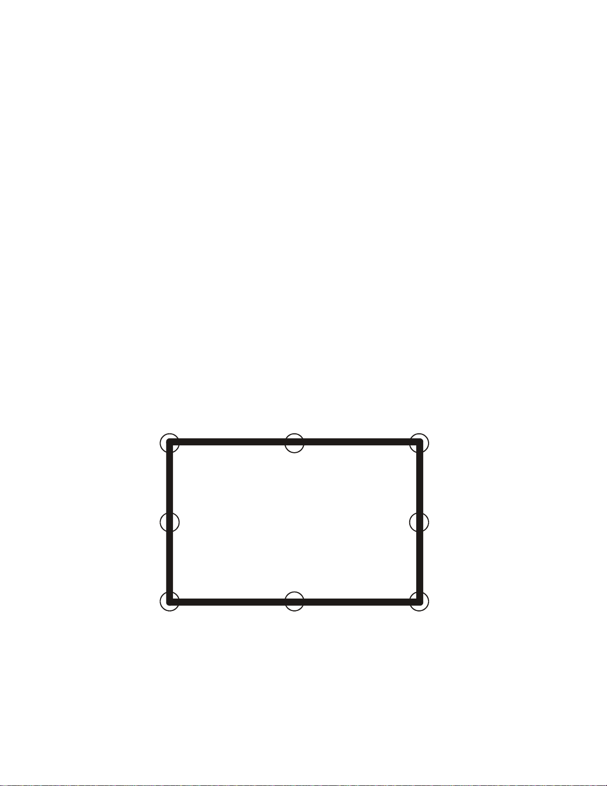
2. Using the convergence pattern, determine the proper raster size by comparing the replacement
to the existing CRT patterns. Move the yoke up and down on the CRT neck until the size of
the replacement pattern matches the size of the existing patterns. Fix the yoke when size
and orientation are acceptable.
3. Still using the convergence pattern, if required use the “Centering Ring Setup” procedure
in the Geometry section, adjusting the centering rings to provide the proper alignment of
the crosshairs of the replacement to the existing CRTs. See the section on Geometry for
more detailed centering ring alignments.
4. This completes the CRT mechanical alignments. Electrical adjustments should not be
required.
5. In the Field Service Menu enter the Convergence menu. If convergence appears acceptable
run “Sensor Calibration”. If “Sensor Calibration” is successful, run autoconvergence and
again observe convergence. If it is acceptable repairs are complete. If it is not continue
with convergence procedures to realign the instrument.
SSB MODULE REPLACEMENT
If convergence is required due to an SSB module replacement always attempt to download the
convergence alignments from the original SSB module. Refer to Appendix A, Chipper Check, for
the procedures. When the original settings are uploaded to the new SSB the convergence alignments
will not be perfect. However they will provide a better starting point than any default values
could. Before beginning realignment of convergence always check the “Tube Type” settings via
the service menu making certain it matches the CRT type of the instrument. Once the proper Tube
Type has been selected default values for first convergence and then geometry should be loaded.
There are several “fixed” values for geometry that should be set prior to geometry alignments. If
one or more CRTs have been replaced with the SSB, refer to the CRT Replacement procedures
making certain they are completed prior to doing any further convergence or geometry alignments.
Only then should the remainder of the geometry alignments be done. Once geometry is completed
may convergence be done. There are also instructions in the event the original alignments are not
available.

ITC222 Geometry & Convergence Procedures 8
So the proper steps when replacing an SSB module are:
1. Use Chipper Check (Appendix A) to either move the original SSB alignments or place the
default SSB file into the replacement module.
2. Use the Field Service Menu to load the default geometry and convergence files and set the
“Tube Type”.
3. Unless a CRT has also been replaced, make no mechanical adjustments to the CRT and DO
NOT MOVE THE CENTERING RINGS!
4. Refer to the section on Geometry procedures to properly align Geometry but if only one or
two CRT’s have been replaced it is not recommended to change any geometry alignments.
5. Converge the set using the Field Service Convergence Menu following the Convergence
Procedures.
CONSUMER COMPLAINT
Most consumer complaints will center on convergence errors rather than geometry. Consumer
complaints of poor convergence and/or autoconvergence failure should be treated as separate issues.
Geometry errors can adversely affect sensor calibration, which in turn will cause autoconvergence
failure. If autoconvergence fails during the Sensor Calibration routine, suspect geometry errors,
particularly if failure occurs on the first (red) sensors. If all red sensors are located properly it
indicates geometry is most likely OK but gross convergence errors are causing autoconvergence
failures.
Always determine from the consumer if convergence was ever acceptable. If it was, but has drifted
too far off for autoconvergence to bring in successfully, carefully observe the screen before doing
anything. Convergence errors, some less than 1/4”, can drift in over time and may be too far out
for autoconvergence to successfully return to an acceptable condition. In most cases errors of this
nature may be manually returned to acceptance using FSM convergence menu. The only screen
required for these types of errors is Level 3 (15 x 13). Refer to Convergence Procedures for
detailed instructions on manual convergence.
If sensor calibration completes successfully and convergence is close but autoconvergence fails,
suspect one or more of the outer points, those adjustment locations located outside the frame
perimeter, are too far off to allow convergence to bring it in. This is the most difficult scenario as
the points cannot be seen. The failure location and careful observance of the screen may provide
a clue as to where the pattern is off. For example, in the next screen,

ITC222 Geometry & Convergence Procedures
9
the upper mid lines are distorted upwards. In this case only green was affected so only the green
adjustment pattern is required. The remainder of the pattern appears to be acceptable. By observing
the pattern it can be determined it is not the third line down that is the problem. If that point is
adjusted it will be found that it cannot be moved downward. That indicates the convergence
amplifier has railed and no longer has the ability to push the adjustment point down. Turning
attention to the lines above it, note the entire top line is distorted, with some of the lines being too
close to the screen frame boundary and others too far away. Notice where the adjustment crosshair
is located. That is where the distortion begins. By going two points above that location the
adjustment crosshair is now off-screen. That point should be pushed upwards moving the lines
closer to the frame, flattening the border lines. Moving to the right two places the adjustment
point should be lowered which pushes the lines away from the frame again flattening out the
border lines. Using this method pressure on the distorted third line weakens and adjustment returns.
If convergence was never acceptable pull up the convergence pattern and observe it for gross
errors in small portions of the screen or in only one color. If errors affect only one color or are
minor in appearance convergence alignment is probably all that is necessary. Refer to the
Convergence Procedures section.
Remember there are six convergence amplifiers, one each for Green, Red and Blue horizontal, and
one each for Green, Red and Blue Vertical corrections. If any one amplifier fails only one color in
one direction will fail. The resulting pattern will have no convergence correction in either the
horizontal or vertical direction and in only one color. The test is to determine if the alignment
points can be moved. If they cannot be moved either up/down, or right/left and only one or more
colors, amplifier failure is indicated. However if all three colors are affected similarly suspect
convergence power supply problems or SSB failure.
AUTOCONVERGENCE FAILURE
Autoconvergence failures can happen for two reasons. Autoconvergence consists of two separate
routines, Sensor Calibration and Autoconvergence. When autoconvergence fails the most recent
successful autoconvergence alignment values are placed back into the registers. So if
autoconvergence fails during sensor calibration but convergence is otherwise very close or even

ITC222 Geometry & Convergence Procedures 10
acceptable, geometry misalignment is indicated. That is because during sensor calibration
convergence is loaded with “neutral” values to make certain there is the least influence of
convergence while the circuit is attempting to find the screen sensors. Since the sensors are actually
located off-screen neutralizing convergence is the safest way to assure the sensors are found. When
Sensor Calibration fails, check the Event History. If the Test results indicate “Brightness” has
failed geometry is probably at fault. The geometry service menu may be used to make geometry
adjustments (See Geometry Procedures).
If the sensor calibration routine completes successfully, but autoconvergence fails, then one or
more convergence alignments are too far off for the autoconvergence amplifiers to correct. Once
sensor calibration completes and autoconvergence begins the convergence alignment points are
loaded with convergence values that are stored in the current mode EEPROM. If autoconvergence
fails at this point, the values that were in RAM are reloaded so the screen will have the original
appearance. The values in RAM may differ from the current mode EEPROM. Refer to Appendix
D, Field Service Menu to determine how to identify the color and area convergence stops on and
work on that specific area.
The ITC222 service adjustments are forgiving. In most cases it is not necessary to store adjustments
immediately!!! The service menu will remember the values before adjustments began allowing
the return to previous alignment values if necessary. Once alignments are verified to provide
acceptable performance, always return to the geometry menu and store the new values so they
become the defaults. Sensor calibration failure is also logged in the Event History screen of the
service menu. It will list the sensor number and color that failed during the sensor location routine.
The location of the failure is also a reasonable clue as to where the problem is. The eight screen
sensors are located in order by color beginning with Red, then Blue, then Green. If there is a
failure of the red color in the first attempt chances are geometry is too far off. Noting which side
of the screen the sensor failed indicates which geometry adjustment should be made.
123
45
678
Remember there are 11 individual vertical points on each side of the screen and 13 horizontal
points on the top and 15 on the bottom of the screen plus one point on each corner that are actually
located “off” the screen. Those adjustments can actually drive the sensor position too far causing
autoconvergence to fail. That is the relationship between geometry and convergence. Both must
be successful for the complete autoconvergence routine to work.

ITC222 Geometry & Convergence Procedures
11
CONVERGENCE PATTERN
The object of any convergence procedure is to return convergence to the out of box alignment
condition. Aproperly converged pattern will appear similar to the following picture of an ITC222
instrument at the end of the production facility. (Some enhancement has been done to highlight
the onscreen pattern.) The display represents a properly convergence instrument and how it should
look before being returned to a consumer.
Ali
gnment
P
o
i
nts
Located Outside
Screen Frame
Alignment Points
Located Outside
Sc
r
ee
n Fr
a
m
e

ITC222 Geometry & Convergence Procedures 12
Geometry
OVERVIEW
Although a convergence pattern is available internally successful geometry alignment depends on
a good external test pattern with center crosshair and outer border lines in both 2H and 2.14H scan
rates. (Using the component inputs may be easier as it is the only analog input capable of both
scan rates.) Alternately the component inputs may be used for the 2.14H pattern input and either
the baseband or RF inputs used for 2H.
NOTE: As with other Thomson chassis, the service menu will make adjustments on the
scan rate that is currently onscreen. In other words if the onscreen display is 2H, when the
service mode is entered all adjustments will be performed in the 2H mode. However, if the
“Input” button is used to change the video input, a different scan mode could be entered.
Pay attention to which scan mode is currently being adjusted and make certain that scan
mode is not accidently changed.
The geometry service menu has the alignments listed in the recommended order they should be
performed. There are also several that default settings and probably not require adjustment in
PTV instruments. All adjustments are listed below with their functions and default values.
Title Default Description
V-Slope (480P Only) B0 Vertical Slope adjusts center value of Vert IC inputs
V-Amplitude 68 Vertical Amplitude adjusts height of vertical raster
V-Position A0 Vertical Position adjusts the up/down position of the raster
V-Linearity 60 (Default) Adjusts raster Vertical linearity. If Geometry linearity is close,
this should not be adjusted.
H-Position AC Adjusts the right/left video location on the raster.
H-Amplitude 64 Adjusts the raster width
EW-Amplitude AC Adjusts the EW Amplifier strength

ITC222 Geometry & Convergence Procedures
13
EW-Trap 80 Adjusts the EW tilt of the raster
EW-Symmetry 70 (Default) Adjusts the right/left sides to be equal in tilt. Used sparingly.
EW-Up Corner A4 Adjusts the upper corners right/left location
EW-Low Corner 90 Adjusts the lower corners right/left location
H-Parallel 70 (Default) Adjusts the right/left sides to be parallel.
Breathing A0 (Default) Adjusts the effect of beam current on raster size. If excessive
breathing is noted when switching from dark to light scenes, make
adjustments two steps at a time until breathing is minimized.
Before attempting geometry adjustments, there are several steps that must be taken.
1. Connect the proper signals to place the instrument in the desired scan mode. (Remember
there are two scan modes, 480P, 2H and 1080I, 2.14H that must be aligned separately.)
480P will always be done first!!!
2. Enter the service menu from the standby mode by pressing and holding CH DN and VOL DN
for more than 8 seconds.
3. Select the proper input by pressing the “Input” button on the remote until the desired signal
is onscreen or select a channel by direct accessing it via the remote control.
4. In the service menu select ConvergenceAdjustments, Defaults and select the R/G/B Default.
This loads the default convergence alignments.
5. Return to the “Tube” menu and make certain the correct Tube Type is selected. The Tube
type may be confirmed by looking at the chassis service label. The Tube Type number will
appear in the format “P16LTG000RFA” where P16 is the tube size and the next three letters,
in this case “LTG” signify the Tube Type that will be selected in the Tube service menu.
6. Return to the “Geometry” menu and select “Vertical Slope”. The bottom half of the screen
will be blanked. With a test pattern onscreen that has center crosshairs, adjust until the
center horizontal line drops just below the visible part of the display. It may be easier to
block the red and blue patterns since Green is the only important pattern at this time.
7. Store the new setting by scrolling down to the “Store” selection and pressing “OK” on the
remote control.
The next steps depend on how far off geometry seems to be. If the prior SSB alignments were
uploaded into a replacement SSB geometry should be very close. Adjustments may be better made
by using the internal convergence pattern and an external crosshair or convergence block pattern.
If a CRT or main yoke has been replaced continue to the Centering Ring Adjustments. Otherwise
skip to the “Horizontal Position” setup.

ITC222 Geometry & Convergence Procedures 14
CENTERING RING ADJUSTMENT
Centering Ring adjustment is not required under the following circumstances.
• If no CRT’s, CRT Drivers or main yokes were changed, centering ring adjustment should
not be necessary and it is highly recommended not to move or otherwise adjust them!
• If an SSB module has been replaced that may otherwise cause geometry or convergence
issues, as long as a CRT or main yoke was not changed, the centering rings do not require
adjustment!
Centering Ring adjustment may be required for the following circumstances.
• If only one CRT, CRT Driver Board or MainYoke was replaced use the convergence pattern
and centering rings for the replacement color to align the pattern back to the patterns on the
CRT’s not replaced.
•If multiple CRTs, CRT driver boards or Main Yokes have been replaced Centering Ring
adjustment will be required.
To begin Centering Ring adjustment disconnect the convergence amplifiers from the convergence
yoke (connector BW001/002) thereby providing a pattern free from convergence influence for the
next steps.
1. Connect the proper signals to provide sync to the instrument. Centering Ring alignment is
not dependant on the deflection frequency but the pattern generator needs sync to provide a
stable display.
2. Enter the service menu from the standby mode by pressing and holding CH DN and VOL DN
for more than 8 seconds.
3. Select the proper input by pressing the “Input” button on the remote until the desired signal
is onscreen or select a channel by direct access via the remote control.
4. In the service menu select and enter the Convergence menu. Select the Level 3 (15X13)
adjustment menu and press OK. Then enter the pattern by selecting “Alignment Mode”
and again press OK. This brings up the convergence pattern which makes an excellent
reference for geometry related adjustments.
5. Toggle through the patterns by pressing “OK” until all three colors are visible. The color
patterns will be offset from each other with Green being closest to exact center. The
following steps depend on the repair. Always align a replacement CRT or yoke to the ones
not replaced!
6. If Green was replaced, use the centering rings on the green CRT to place the center crosshair
of the convergence pattern in the center of the screen both horizontally and vertically. (If
Green was not replaced, do not move it! Align the red or blue CRT pattern to the green.)
7. If red or blue was replaced adjust the Red and Blue crosshair such that the center horizontal
lines lay exactly on top of the green center line. Adjust the Red crosshair such that the
center vertical line is to the left of the Green or the Blue crosshair such that the center
vertical line is to the right of the Green. Use the following table to determine how far right
or left the lines should be.

ITC222 Geometry & Convergence Procedures
15
eziSneercS retneCdeR tfeLteSeniL :ybneerGfo
retneCeulB thgiRteSeniL :ybneerGfo
"04"1"1
"25"4/11"4/11
"65"61/51"61/51
"16"8/31"8/31
The final pattern will appear similar to the next graphic:
This completes the Centering Ring setup. Exit the Field Service Menu, turn the set off and reconnect
the convergence amplifiers. Turn the set back on, enter the service menu and proceed to the
“Horizontal Position” alignment.
Horizontal Position
Enter the Geometry Menu and select “Horizontal Position”. With a standard crosshair pattern
onscreen, adjust horizontal position to place the vertical crosshair in the center of the screen.
Neither Vertical Slope, Horizontal Position or the centering rings should be adjusted again
regardless of other changes to convergence or geometry!!! Horizontal Position may require
additional alignment but only after all other convergence and geometry alignments are
completed.

ITC222 Geometry & Convergence Procedures 16
GEOMETRY ALIGNMENT
Once preliminary geometry setup and/or Centering Ring adjustments have been completed, geometry
alignment may proceed. Geometry alignment, while not being critical must be reasonably close to
the final convergence pattern. The two main purposes of geometry alignment in the ITC222 are to
assure the convergence amplifiers are not overworked and to provide a reference for the sensor
calibration routine. A diagram of the final geometry pattern appearance without convergence
correction is shown below. Note that although the pattern is shown above the frame, it cannot be
seen during the alignments. It is shown below simply as a reference to how the pattern would
actually appear if no convergence corrections are available. The important alignment points are
circled and refer to the third vertical line outward from the center line. That point should “bump”
the frame very closely as shown. Remember that while the pattern may not exactly match the one
below, it should appear very similar.
Geometry (and later convergence) procedures are simplified if the initial adjustments are done
without convergence correction. All geometry adjustments can be properly setup using a pattern
without convergence correction. But to finalize Linearity and EW corrections it is best to reconnect
the convergence yokes then bounce back and forth between the geometry menu with an external
pattern to perform adjustments, and the convergence menu with the internal convergence pattern
to view the results. After geometry adjustments are completed and the convergence yokes are
reconnected it is best not to make further adjustments on the following alignments:
Vertical Amplitude,
Vertical Position,
Horizontal Amplitude.
Small changes may still be required on the other geometry adjustments however they should be
very minor. Also remember that Horizontal Position should not be adjusted until all geometry and
convergence alignments are completed.

ITC222 Geometry & Convergence Procedures
17
GEOMETRY CONTROLS
Once all preliminary setups and alignments are complete use the template shown to guide geometry
alignments. The Field Service Menu has alignments in a specific order which should be followed
the first time through any geometry setup particularly after an SSB module replacement. Once all
adjustments have been made in order at least once, further corrections performed in random order
are acceptable. The first settings should also be done with the convergence yokes unplugged so
that only geometry corrections are affecting the raster. Once the pattern appears correct, the
convergence yokes can be reconnected.
The following illustrations demonstrate the effect of each geometry adjustment on the raster. Keep
in mind the proper way to adjust geometry in the ITC222 is to make small adjustments using a test
pattern with known centerlines and outer boundaries, but always doing critical observance by
returning to the internal convergence pattern.
V-Slope Vertical Slope adjusts the center value of the Vertical IC inputs. It has been
previously set and should not be changed at this point.
V-Amplitude Vertical Amplitude adjusts the height of the vertical raster. As previously
described when the convergence yokes are disconnected it is set such that the
third vertical lines from the centerline are just touching the frame.
Vertical Amplitude
V-Position Vertical Position adjusts the up/down position of the raster. It is adjusted to
center the vertical raster from top to bottom. It is acceptable to return to Vertical
Amplitude if required.
V
e
r
t
i
ca
l P
os
i
t
i
o
n

ITC222 Geometry & Convergence Procedures 18
V-Linearity Adjusts rasterVertical linearity. Caution! Changing linearity too much also affects
vertical position. If linearity is close, this should not be adjusted. If it is not,
monitor vertical position and amplitude making certain the vertical size is still
correct and location is centered.
Vertical Linearit
y
H-Position Adjusts the right/left video location on the raster. Since this affects video rather
than raster, it should not be adjusted until geometry and convergence are
completed.
H
o
riz
o
n
ta
l P
os
i
t
i
o
n
H-Amplitude Adjusts the raster width. Refer to the example screen. The outermost pattern
lines should be about 1/2” from the frame. If the raster cannot be perfectly
centered it should always be closer to the left than the right.
Horizontal Amplitude

ITC222 Geometry & Convergence Procedures
19
EW-Amplitude Adjusts the EWAmplifier strength. Monitor the corners of the pattern to provide
equal amplitude on the top and bottom.
EW Amplitude
EW-Trap Adjusts the EW tilt of the raster. Adjust for raster appearance closest to the
template.
EW Trap
EW-Symmetry Adjusts the right/left sides to be equal in tilt. Adjust for raster appearance closest
to the example.
EW S
y
mmetr
y

ITC222 Geometry & Convergence Procedures 20
EW-Up Corner Adjusts the upper corners right/left location. Adjust for raster appearance closest
to the template.
EW Upper Corners
EW-Low Corner Adjusts the lower corners right/left location. Adjust for raster appearance closest
to the template.
EW L
o
w
e
r
Co
rn
e
r
s
H-Parallel Adjusts the right/left sides to be parallel. Adjust for raster appearance closest to
the template.
H P
a
r
a
ll
e
l
Breathing Adjusts the effect of beam current on raster size. If excessive breathing is noted
when switching from dark to light scenes, make adjustments two steps at a time
until breathing is minimized.
Other manuals for ITC222
1
Table of contents