THOR H-2/4HD-EM User manual

FIBER
PRO-DVB H-2/4HD-EM(S/H)
2ch or 4ch HD-SDI
AC3 & CC 608/708
Revision 1.3
Revised 2014

H-2/4HD-EM(S/H)
A Note From Thor About
This Manual
Intended Audience
This user manual has been written to help people who have to use, integrate and to install
the product. Some chapters require some prerequisite knowledge in electronics and
especially in broadcast technologies and standards.
Disclaimer
No part of this document may be reproduced in any form without the written permission of
Thor Broadcast.
The contents of this document are subject to revision without notice due to continued
progress in methodology, design and manufacturing. Thor shall have no liability for any
error or damage of any kind resulting from the use of this document.
Copy Warning
This document includes some confidential information. Its usage is limited to the owners
of the product that it is relevant to. It cannot be copied, modified, or translated in another
language without prior written authorization from Thor Broadcast.

H-2/4HD-EM(S/H)
Directory
Contents
CHAPTER 1 INTRODUCTION .................................................................................................................... 4
1.1 PRODUCT OVERVIEW .............................................................................................................................. 4
1.2 KEY FEATURES ........................................................................................................................................ 4
1.3 SPECIFICATIONS ...................................................................................................................................... 5
1.4 SCHEMATIC OVERVIEW ........................................................................................................................... 6
1.5 IMAGE AND BUTTON CONFIGURATION LAYOUT ...................................................................................... 6
2.1 GENERAL PRECAUTIONS ......................................................................................................................... 7
2.2 POWER PRECAUTIONS ............................................................................................................................. 8
2.3 DEVICE’S INSTALLATION FLOW CHART ILLUSTRATED AS FOLLOWING .................................................... 8
2.4 ENVIRONMENT REQUIREMENT ................................................................................................................ 8
2.5 GROUNDING REQUIREMENT .................................................................................................................... 9
CHAPTER 3 OPERATION ........................................................................................................................ 10
3.1 LCD TREE BREAKDOWN ....................................................................................................................... 10
3.2 INITIAL STATUS ..................................................................................................................................... 11
3.3 GENERAL SETTINGS FOR MAIN MENU .................................................................................................. 11
4.1 LOGIN .................................................................................................................................................... 18
4.2 OPERATION ........................................................................................................................................... 19
CHAPTER 5 TROUBLESHOOTING ........................................................................................................... 26
CHAPTER 6 PACKING LIST ..................................................................................................................... 27

H-2/4HD-EM(S/H)
Chapt r 1 Introduction
1.1 Product Overview
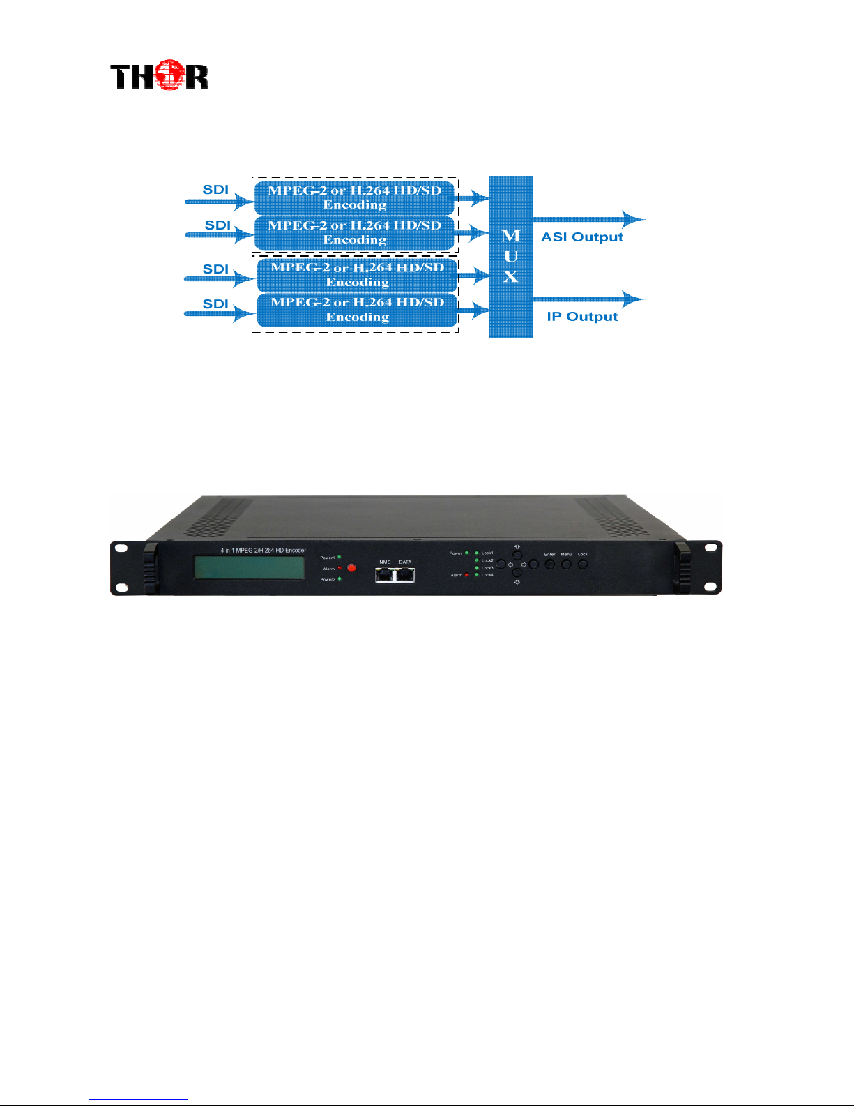
The Thor H-2/4HD-EM is our new pro broadcast featured encoder that features
high end performance with powerful functionality. It comes equipped with 2/4
HD-SDI channel inputs that support: MPEG-2 & H.264 video encoding with
MPEG-1 layer 2, LC-AAC, HE-AAC, and AC3 audio encoding. The 2/4 SDI inputs
will be output via either ASI or IP in MPTS or SPTS.
This encoder will be an ideal chassis to support any DVB-ASI programming as it
adopts the necessities to output AC3 audio and Closed Caption 608 &708. Also
comes’ stock with dual power supply, as a back-up units is on standby to ensure
your unit won’t fail. Structured to facilitate to the demanding needs of any broadcast,
this encoder series is the newest addition to Thor’s Broadcast Encoders.
1.2 Key Features
Dual power supply
MPEG2 HD/SD & MPEG4 AVC/H.264 HD/SD video encoding
MPEG1 Audio Layer 2, LC-AAC, HE-AAC and AC3 audio encoding
4*HD-SDI input
Support VBR/CBR rate control mode
Support CC (closed caption) EIA 608 & EIA708
Low Latency function
Supports PSI/SI editing and inserting
Supports IPnull packet filter
ASI output, IP(MPTS & 4 SPTS) output over UDP, RTP
LCD display, Remote control and firmware
Web-based NMS management; Updates via web

H-2/4HD-EM(S/H)
1.3 Specifications
Encoding S ction
Vid o
Encoding MPEG2 & MPEG4 AVC/H.264
Input H -S I*4
Resolution
1920*1080_60P, 1920*1080_50P, (-for MPEG4 AVC/H.264 only)
1920*1080_60i, 1920*1080_50i,
1280*720_60p, 1280*720_50P
720*480_60i, 720*576_50i
Bit Rate 0.5~19.5Mbps for H.264 encoding
1~19.5Mbps for MPEG-2 encoding
Rate Control Mode CBR/VBR
Audio
encoding MPEG1 Layer II, MPEG2-AAC, MPEG4-AAC, olby igital AC3
Sample rate 48KHz
Bit rate 64kbps, 96kbps,128kbps, 192kbps, 256kbps, 320kbps
Syst m
Local interface LC + control buttons
Remote management Web NMS
Low Latency Mode Normal, mode 1, mode 2
output 2*ASI out (BNC type);
IP (1 MPTS & 4 SPTS) over U P, RTP (RJ45, 100M)
NMS interface RJ45, 100M
Language English
G n ral
Power supply AC 100V~240V
Power Consumption 45W
imensions 482*400*44mm
Weight 4.5 kgs
Operation temperature 0~45℃
H-2/4HD-EM(S/H)
1.4 Schematic Overview
1.5 Image and Button Configuration Layout
8 1 2 3 4 5 6 7 8
①
①①
①LCD window
②
②②
② Pow r supply indicators
③
③③
③ Pow r Alarm Switch: Wh n only on pow r supply is conn ct d or on of th pow r
suppli s fails, th d vic will giv alarm sound, and th n pr ss th alarm switch to turn off th
alarm sound.
④
④④
④ NMS port for th conn ction b tw n th d vic and PC
⑤
⑤⑤
⑤ DATA port for IP signal out
⑥
⑥⑥
⑥
Indicators for whol unit pow r supply, working alarm and input signal lock status
⑦
⑦⑦
⑦ Control Buttons
⑧
⑧⑧
⑧ Handl s

H-2/4HD-EM(S/H)
1 2 3 4 56
①
①①
①SDI Input Modul 1: Program input port 1&2
②
②②
②SDI Input Modul 2: Program input port 3&4
③
③③
③ASI output ports
④
④④
④Pow r Supply Slot
⑤
⑤⑤
⑤Pow r Switch
⑥
⑥⑥
⑥Grounding
Chapter 2 Installation Guide
Please use caution when operating this device in order to abstain from any possible
injury during installation. For this reason, please read all details listed below and make
and use caution before proceeding to operate and use this electronic equipment.
2.1 General Precautions
Must be operated and maintained in an area free of dust and debris.
The cover should be securely fastened, do not open the cover of the chassis when the
power is on. This will also void Thor’s manufacturer’s warranty.
After installation, securely stow away all loose cables, external antenna, and others.

H-2/4HD-EM(S/H)
2.2 Power Precautions
Be careful when connecting a power source to the device.
Do not operate in wet or damp areas. Make sure the extension cable is in good
condition
Make sure the power switch is off before you start to install the device
2.3 Device’s Installation Flow Chart Illustrated as following
2.4 Environment Requirement
Item Requirement
Machine Hall
Space
When user installs machine on rack, the distance between 2
rows of machine frames should be 1.2~1.5m and the distance
against wall should be no less than 0.8m.
Machine Hall Floor
Electric Isolation, Dust Free
Volume resistivity of ground anti-static material:
1X10
7
~1X10
10
Ω,Grounding current limiting resistance: 1MΩ
(Floor bearing should be greater than 450Kg/㎡)
Environment
Temperature 5~40℃(sustainable ),0~45℃(short time),
installing air-conditioning is recommended
Relative Humidity 20%~80% sustainable 10%~90% short time
Pressure 86~105KPa
Door & Window Installing rubber strip for sealing door-gaps and dual level
glasses for window
Wall It can be covered with wallpaper, or brightness less paint.

H-2/4HD-EM(S/H)
Fire Protection Fire alarm system and extinguisher
Power
Requiring device power, air-conditioning power and lighting
power are independent to each other. Device power requires
AC 110V±10%, 50/60Hz or AC 220V±10%, 50/60Hz. Please
carefully check before running.
2.5 Grounding Requirement
It is important to keep this device grounded to ensure all of the modules
function correctly. Correctly grounding the device will also help prevent any
electrical interference, lightening. Etc. Also it helps reject minor interference that
may disrupt the devices ability to function smoothly. General rule of them, make
sure the device is grounded when installing anywhere.
Always use copper wire. When applied correctly the ground must be wrapped
well to ensure maximum conduction so it can reduce any high frequencies. The
copper ground wire should also be as short and thick as possible
Installer must make sure that the two ends of the ground are well conducted
and have appropriate anti-rust properties.
It is prohibited to use any other device as part of the grounding electric
circuit.
The area of the conduction between the ground wire and device’s frame
should be no less than 25 ㎡.
H-2/4HD-EM(S/H)
Chapt r 3 Op ration
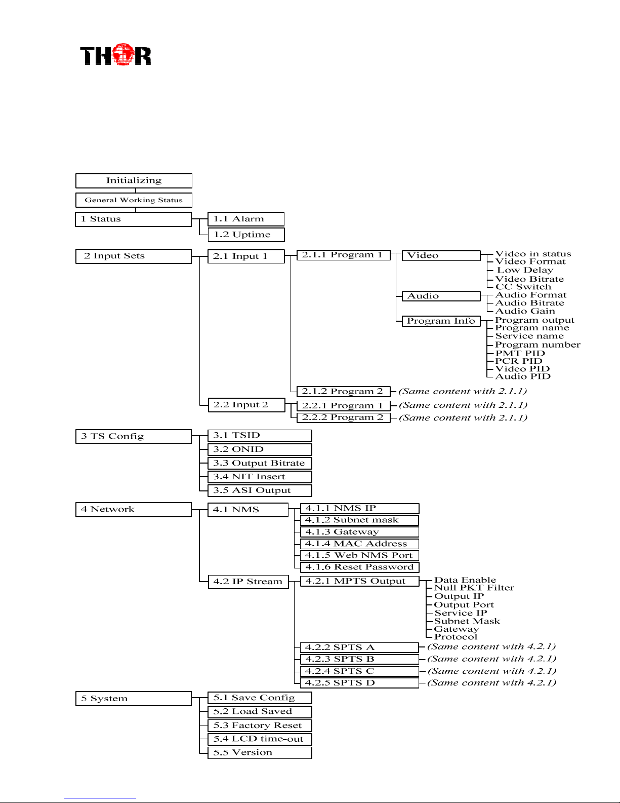
3.1 LCD Tree Breakdown

H-2/4HD-EM(S/H)
3.2 Initial Status
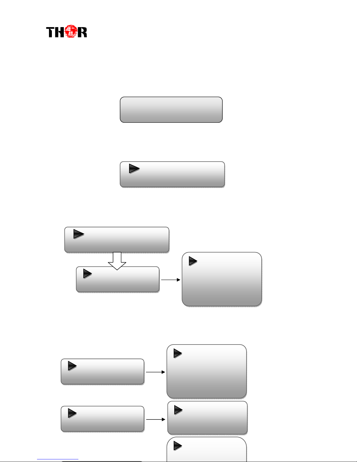
Switch on the device and after a few seconds’ initialization, it presents start-up pictures as
shown below:
H-HD-EM: Module name and number
P1: Program 1; P2: Program 2; P3: Program 3; P4: Program 4
X.XX Mbps: indicate the current encoding bit rate of the corresponding channel.
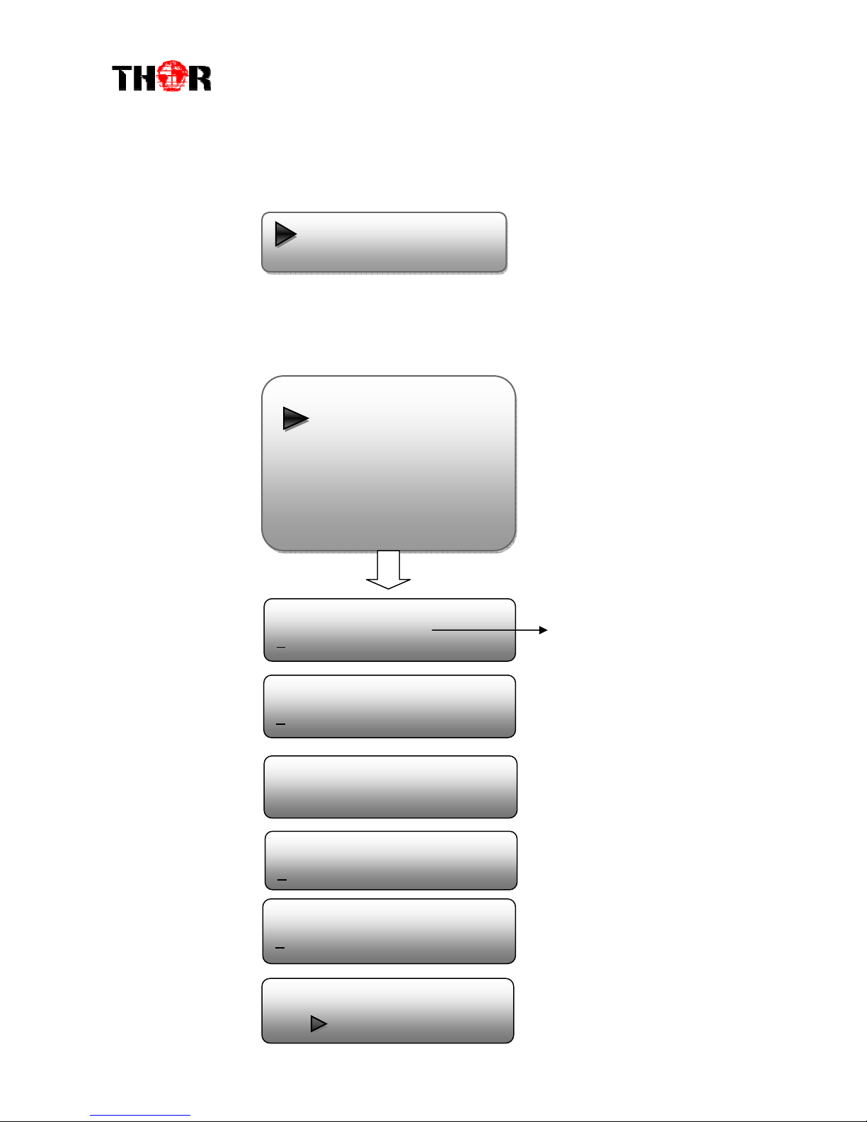
3.3 General Settings for Main Menu
Press “Lock” key on the front panel to enter the main menu. The LCD will display the
following pages where user can configure the parameters for the device:
User can press UP/DOWN buttons to specify menu item, and then press ENTER to
enter the submenus as below:
1) Status
Start up… Start OK… H-H -EM H ENCO ER
P1:X.XXMbps P2: X.XXMbps
1 Alarm Status
2 Encod S tting
3 Modulat S tting
4 IP Output S tting
5 N twork S tting
6 Saving Config
7 Loading Config
8 V rsion
1.1 Alarm
1.2 Uptim
H-2/4HD-EM(S/H)
Alarm
The alarm indicator will turn on if there is no A/V signals inputting or outputting bit
rate overflows. User then can enter this menu to check the error type.
Uptime
It displays the working time duration of the device. It times upon power on.
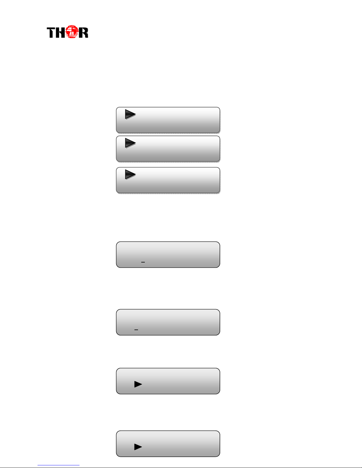
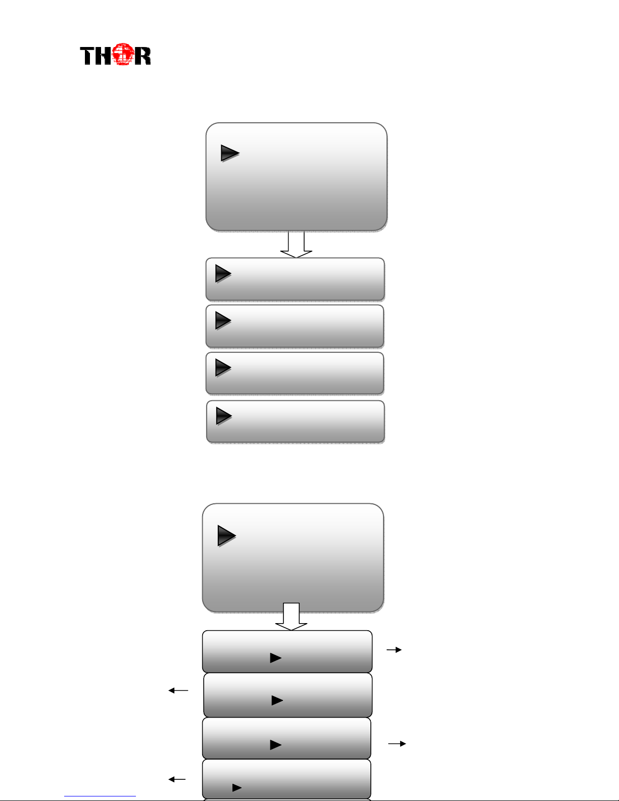
2) Input Settings
Under this submenu, the LCD will show “2.1 Input 1” and “2.2 Input 2” to represent
the two SDI-input modules respectively.
Each SDI input module support two program input connecters. Under submenus 2.1
(or 2.2), user could set the video/audio parameters for the 2 SDI programs respectively.
2.1 Input 1
2.2 Input 2
Uptim
0 Day(s) xx-xx-xx
2.1.1 Program 1
2.1.2 Program 2
Vid o
Vid o in status
Vid o Format
Low D lay
Vid o Bit Rat
CC Switch
Vid o
Vid o in status
Vid o Format
Low D lay
Vid o Bit Rat
CC Switch
Audio Audio Format
Audio Bit rat
Audio Gain
Program output
Program nam
S rvic nam

H-2/4HD-EM(S/H)
Video in Status
Users can enter this menu to check the video input status.
Video Format
The SDI encoding module supports both “MPEG2” and “H.264” video encoding
formats. Users can enter this menu to select one format from the 2 options.
Press ENTER to shift ‘*’ to ‘►’, and then press UP/DOWN buttons to specify one item and then press
ENTER to confirm. Press MENU to step back to upper level menu. (The operation method is applicable
for rest part.)
Low Delay
This unit can achieve a low time delay from encoding to decoding terminal
end-to-end.
…..……………………………….....
NOTE
……..……..………………………….
The different combination of Video Format, Video Bit-rate, Low Delay Mode, the
Resolution of signal source and Decoding solution adopted on terminal side will have an
impact on the latency.
…………………………………………………………………………………………..……
Video Bit Rate
Users can set the video encoding bit rate manually in this menu.
0.5~19.5Mbps for H.264 encoding
1~19.5Mbps for MPEG-2 encoding
CC Switch
CC refers to Closed Caption.
Users can select a standard for the CC from the 2 options in this menu.
MPEG2
H.264
Normal
Mod 1
Vid o Bit Rat
14.000 Mbps
►EIA 608
EIA 708

H-2/4HD-EM(S/H)
Audio Format
The SDI encoding module supports 4 encoding formats. Users can enter this menu to
select one format’s from the 4 options available.
Audio Bit Rate
The audio bit rate ranges from 64Kbps to 320Kbps. Users can select one bit-rate from
the options provided.
Audio Gain
Users can adjust the audio gain in this menu.
Program Info
Users can enable or disable the program output in the first sub-menu and configure the
other parameters in the rest sub-menus.
MPEG1 Lay r 2
MPEG2 AAC
MPEG4 AAC
AC3
Audio Bitrat
64Kbps
Audio Gain
100 %
Program Output
Enabl
Program Nam
TV-101
S rvic Nam
TV-Provid r
Program numb r
0x101
PMT PID
0x101
PCR PID
0x100
Vid o PID
0x100
Audio PID
0x100
H-2/4HD-EM(S/H)
3) TS Configuration
This encoder support TS output via ASI ports. ‘TS Config’ is for the configuration of
ASI output. Its submenus contain:
TS ID/ ON ID
Users can set the TS ID and Original Network ID in the 2 submenus. The IDs are in
hexadecimal form.
Output Bit rate
Users can set the max output bit rate for the ASI MPTS out. (Range 0-100 Mbps)
NIT Insert
Users can insert your NIT with operations in the menu.
ASI Output
Users can copy a stream from the IP out streams (1 MPTS & 8 SPTS) to output through
ASI.
3.1 TS ID
3.2 ON ID
3.3 Output Bit rat
3.4 NIT Ins rt
3.5 ASI Output
ON ID
0x0001
Output Bit rat
60.000 Mbps
NIT Ins rt
Y s No
ASI Output
MPTS
H-2/4HD-EM(S/H)
4) Net Work
‘Net work’is divided into 2 parts: NMS and IP Stream.
NMS
Submenus under ‘NMS’ are for setting the parameters related to the device connection
in the network.
4.1 NMS
4.2 IP Str am
NMS
4.1.1 NMS IP
4.1.2 Subn t Mask
4.1.3 Gat way
4.1.4 MAC Addr ss
4.1.5 W b NMS Port
4.1.6 R s t Password
NMS IP
192.168.000.136
The IP address for connecting
the device to PC
Subn t Mask
255.255.255.000
Gat way
192.168.000.001
MAC Addr ss
201012345678
W b NMS Port
00080
R s t Password?
Y s NO
H-2/4HD-EM(S/H)
IPStream
Submenus under ‘IP Stream’are for setting the output IP stream in MPTS or SPTS.
5) System
Users can set the system parameters in this menu. Enter ‘System’ submenus to
separately set corresponding parameters.
Data Enabl
Null PKT Filt r
Output IP
Output Port
S rvic IP
Subn t Mask
Gat way
Protocol
IP Str am
4.2.1 MPTS Output
4.2.2 SPTS Output A
4.2.3 SPTS Output B
4.2.4 SPTS Output C
4.2.5 SPTS Output D
Syst m
5.1 Sav Config
5.2 Load Sav d CFG
5.3 Factory R s t
5.4 LCD Tim -out
5.5V rsion
Sav Configuration?
Y s
No
Load Sav d CFG?
Y s
No
R s t All S ts?
Y s
No
LCD Tim -out
30 s
Choose yes to save settings.
and press ENTER to confirm
Choose yes to restore the
device into factory’s default
configuration.
It displays the
device name
Choose yes to restore the
device into the last saved
configuration.
Press DO N/UP key to select
a time out for the LCD lighting
duration (5-120 seconds)
H-2/4HD-EM(S/H)
Chapt r 4 WEB NMS Op ration
Using the LCD digital display and front buttons for setting configuration is always
an option if you are close by, conveniently you can alter the same settings through a
computer by connecting the device to the web NMS Port. Always make sure that
the computer’s IP address is different from the Units IP address; otherwise, it will
cause an IP conflict. Below is an explanation of how you can adjust settings
through a web portal
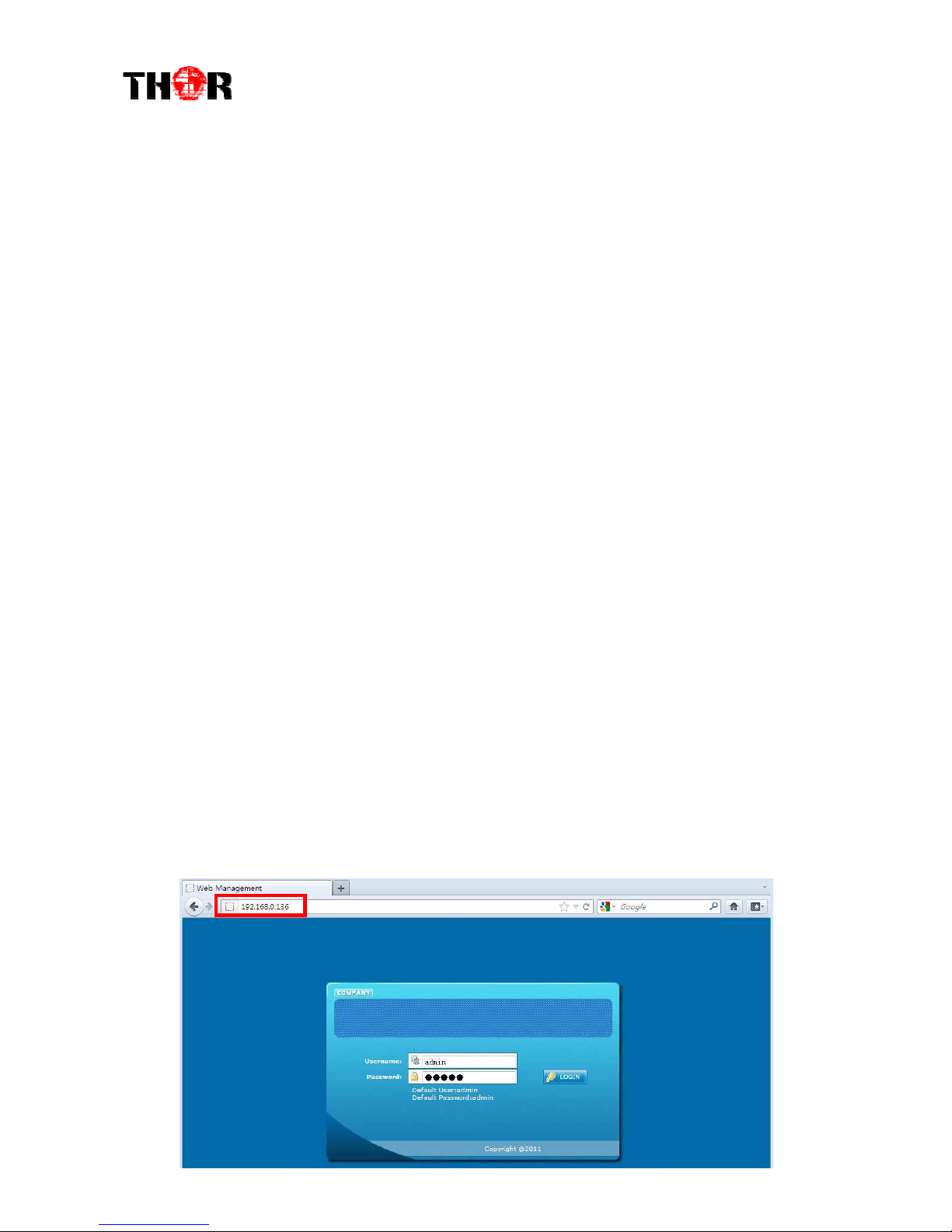
4.1 login
The default IP address of this device is 192.168.0.136. (We can modify the IP through
the front panel.)
Connect the PC (Personal Computer) and the device with an ethernet cable, and use
ping command to confirm they are on the same network segment.
NOTE* if the PC IP address is 192.168.99.252, we then change the device IP to
192.168.99.xxx (xxx can be 1 to 254 except 252 to avoid IP conflict).
Use web browser to connect the device with a PC by inputting the encoders IP address
in the browser’s address bar and press Enter.
It will display the Login interface as Figure-1. Input the Username and Password
(Both the default Username and Password are “admin”.) and then click “LOGIN” to
start the device setting.
Figure-1

H-2/4HD-EM(S/H)
4.2 Operation
When we confirm the login, it displays the WELCOME interface as shown in Figure-2.
Figure-2
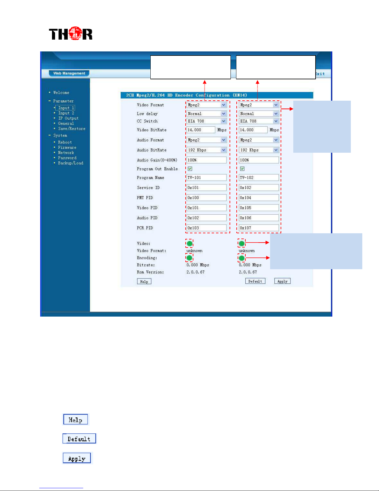
Input 1
From the menu on left side of the webpage, click “Input 1”, it displays the
information of the programs (1
st
& 2
ed
ones) from the 1
st
SDI encoding module as
Figure-3.
It automatically
identifies and
displays the signal
source interface and
real-time encoding
bit rate of
corresponding input
channel.
User can click any item
here to enter the
corresponding interface to
check information or set the
parameters.
TS indicators—Green
light indicates the TS is
normal, which otherwise
turns to red.
H-2/4HD-EM(S/H)
Figure-3
…..……………………………….....
NOTE
……..……..………………………….
The different combination of Video Format, Video Bit-rate, Low Delay Mode, the
Resolution of signal source and Decoding solution adopted on terminal side will have an
impact on the latency.
…………………………………………………………………………………………..……
For user to turn to refer detailed explanation of terms on this interface
Click this button to apply the default setting of Input 1
Click this button to apply the modified parameters.
This column is for setting
the 1
st
S I IN program.
This column is for setting
the 2
d
S I IN program.
Encoding Status—Green light
indicate it works normally,
which otherwise turn to red.
General Settings
for the S I IN
programs: User
can edit any item
listed as needed.
Table of contents
Other THOR Media Converter manuals


