THORLABS ScienceDesk SDA Series User manual

ScienceDesk
SDA Series
SDP Series
SDH Series
SDR Series
User Guide
Original Instructions

0 HA0200T Rev 11 Jun 2022
Contents
Chapter 1 Introduction .........................................................................................................................................3
1.1 General Description ............................................................................................................................................3
1.2 Accessories ........................................................................................................................................................3
Chapter 2 Safety ...................................................................................................................................................4
2.1 Safety Information ..............................................................................................................................................4
2.2 General Warnings ..............................................................................................................................................4
Chapter 3 Basic Installation ................................................................................................................................5
3.1 Installing the Frame ............................................................................................................................................5
3.2 Fitting the Casters ..............................................................................................................................................5
3.3 Installing the Breadboard ...................................................................................................................................6
3.3.1 Rigid Mounts .........................................................................................................................................................................6
3.3.2 Passive Mounts .....................................................................................................................................................................7
3.3.3 Active System ......................................................................................................................................................................10
3.4 Accessories .......................................................................................................................................................12
Chapter 4 Considerations For Ergonomic Layout .........................................................................................13
4.1 Working Height .................................................................................................................................................13
4.2 Ergonomic Guidelines ......................................................................................................................................13
Chapter 5 Packing List .......................................................................................................................................15
Chapter 6 Declaration of Conformity ................................................................................................................16

1
ScienceDesk Workstation
Chapter 1 Introduction
1.1 General Description
The SDA Series Science Desks are active vibration isolation systems used to isolate a breadboard from vertical and
horizontal vibrations in order to provide a stable platform for sensitive experiments and applications.
The SDP Series are passive vibration isolation systems used in an environment where vibration is less critical, and can bear
a load of up to 260 kg (570 lbs).
The SDH Series are also passive vibration isolation systems. However, they are designed to bear a heavier load than the
SDP Series - up to 700 kg (1545 lbs).
The SDR Series are rigid, non-isolating systems for use in environments where vibration isolation is not required.
The basic ScienceDesk includes a frame consisting of four legs connected with tie bars. A breadboard, is supported on
vibration isolation mounts and provides a stable platform on which to populate system components. Various accessories
can be added (e.g. PC shelves, monitor mounts, wrist supports etc.) to customize the workstation as required – see Fig.
1.1 for a typical layout and www.thorlabs.com for more details.
Fig. 1.1 Typical layout
The frame is drilled with 17mm diameter through holes on a 100mm pitch to facilitate the mounting of customer designed
accessories or components as required.
Throughout this handbook, all examples refer to a standard height desk. A standing height option is also available and all
instructions apply eually to these variants.
1.2 Accessories
Thorlabs provide a range of accessories to assist in the mounting of ancilliary components, please see www.thorlabs.com
for more details.

2 HA0200T Rev 11 Jun 2022
Chapter 2
Chapter 2 Safety
2.1 Safety Information
For the continuing safety of the operators of this equipment, and the protection of the equipment itself, the operator should take
note of the Warnings, Cautions and Notes throughout this handbook and, where visible, on the product itself.
The following safety symbols may be used throughout the handbook and on the equipment itself.
2.2 General Warnings
Warning: Risk of Electrical Shock
Given when there is a risk of injury from electrical shock.
Warning
Given when there is a risk of injury to users.
Caution
Given when there is a risk of damage to the product.
Note
Clarification of an instruction or additional information.
Warning
Do:
Ensure that the ScienceDesk is securely positioned prior to any work being undertaken on the system.
If using the ScienceDesk with any electrical equipment, incorporate appropriate earthing and/or other safety circuitry
as required by national standards to protect the operator.
When lifting or moving components, ensure that the proper posture is maintained. Do not lift loads in excess of
nationally recognized safe working limits (25kg per operator in Europe). If in doubt use an appropriately designed
lifting device.
Before lifting the breadboard, ensure it is unpopulated.
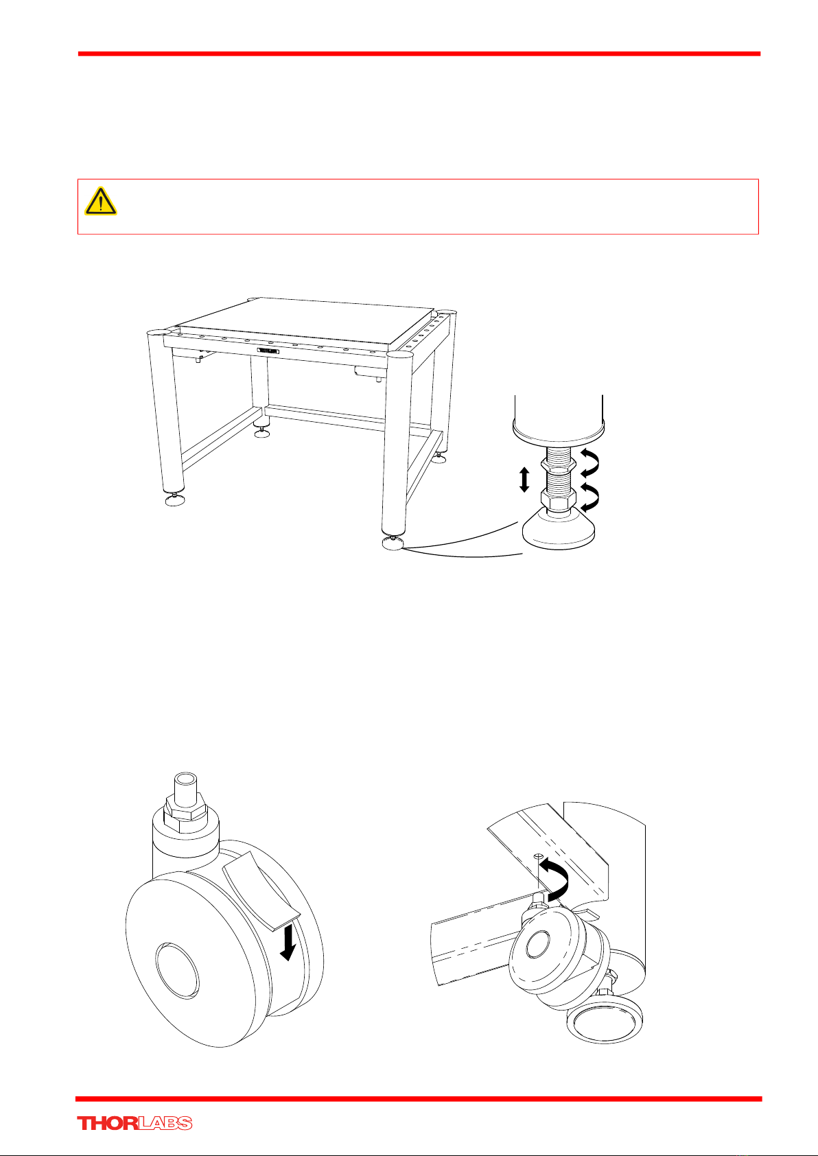
If the optional casters are fitted, ensure that the feet are fully retracted before moving the ScienceDesk.
Exercise particular caution if moving the ScienceDesk on a sloping surface.
Ensure all fixings are secure prior to use.
Do not:
Get into any position where you can be trapped between a wall, door frame or other immovable object and the
ScienceDesk.
Go underneath the ScienceDesk when the unit is being moved.
Move an active system when the breadboard is floating on its isolators.
Tow the ScienceDesk with any powered device.
Ride on the ScienceDesk.
Move the ScienceDesk over uneven ground.
Leave the system on its castors for prolonged periods of time.
Leave the system unattended on its castors without applying the brakes.
Sit or stand on the desk unit or any accessory
Caution
Before attempting to assemble/fit any accessories or modify the workstation layout, refer to Section 4 –
‘Considerations For Ergonomic Layout’ of the handbook supplied with the ScienceDesk, together with the sections
which relate to particular accessories.
Ensure that proper airflow is maintained to any electrical equipment installed on the ScienceDesk.
The ScienceDesk is designed only for indoor use.

3
ScienceDesk Workstation
Chapter 3 Basic Installation
3.1 Installing the Frame
1) Remove all packaging.
2) Install the frame in the location in which it is to be used.
3) Loosen the locking nuts and adjust each foot until the castors are clear of the ground (if fitted) and the frame is level –
see Fig. 3.1. Use a suitable levelling device.
Fig. 3.1 Levelling the frame
3.2 Fitting the Casters
Referring to Fig. 3.2
1) Push down the lever on each caster to lock the rotation of the wheels on the shaft.
2) Adjust the feet to raise the frame sufficiently to allow the casters to be fitted in the lower support rails.
3) Insert the threaded shaft into the locating hole, and turn the complete caster assembly to screw the shaft into the frame
4) Repeat item (3) for the remaining 3 casters.
5) Retract the feet until the casters are in contact with the ground.
6) Position the ScienceDesk as required.
7) Adjust the feet to level the frame - see Section 3.1.
Fig. 3.2 Fitting Casters
Warning
During item (2), safe lifting precautions must be observed. In particular, do not lift more than 25 kg (55 lb) per person.
Use more people or lifting apparatus as necessary. Frame weights are detailed on www.thorlabs.com.

4 HA0200T Rev 11 Jun 2022
Chapter 3
3.3 Installing the Breadboard
3.3.1 Rigid Mounts
The breadboard rests on rubber pads, three in each corner of the frame. Levelling of the work surface is acheived by adjusting
the feet.
A Installation
1) Ensure the frame is correctly sited and level – see Section 3.1.
2) Fit the lifting handles supplied to the breadboard as shown.
3) Observing the warnings listed above, lift the breadboard into position.
4) Use a suitable levelling device to check the breadboard is level. Repeat Section 3.1. as necessary.
5) Tighten the locknuts on the feet.
6) Populate the breadboard.
Fig. 3.3 Fitting the breadboard
B Removal
To remove the breadboard, reverse the installation procedure.
Note
The desk is normally supplied with the anti-vibration mounts and breadboard already fitted. Item (2) is applicable only if the
unit has been shipped or air-freighted to its destination
Warning
During item (2):
When lifting breadboards, use the lifting handles supplied.
Safe lifting precautions must be observed. In particular, do not lift more than 25 kg (55 lb) per person.
Use more people as necessary.
Breadboards should be lifted only in an unpopulated condition.
Caution
During item (6), the total load including the breadboard must not exceed 700kg (1545 lb).
Warning
During item (2):
When lifting breadboards, use the lifting handles supplied.
Safe lifting precautions must be observed. In particular, do not lift more than 25 kg (55 lb) per person.
Use more people as necessary.
Breadboards should be lifted only in an unpopulated condition.

5
ScienceDesk Workstation
3.3.2 Passive Mounts
Equipment Required:
Levelling device (e.g., bubble level)
Foot pump (automobile tire type)
A Installation
1) Ensure the frame is level – see Section 3.1.
2) Remove the dust caps from the schraeder valves – see Fig. 3.4
Fig. 3.4 Passive anti-vibration mount
3) Fit the lifting handles supplied to the breadboard as shown in Section 3.3.1.
4) Observing the warnings listed above, lift the breadboard into position.
Note
The desk is normally supplied with the anti-vibration mounts and breadboard already fitted. Steps (2) to (6) are applicable
only if the unit has been air-freighted or shipped to its destination.
Warning
During item (3):
When lifting breadboards, use the lifting handles supplied.
Safe lifting precautions must be observed. In particular, do not lift more than 25 kg (55 lb) per person.
Use more people as necessary.
Breadboards should be lifted only in an unpopulated condition.
A

6 HA0200T Rev 11 Jun 2022
Chapter 3
5) Connect the foot pump to the mount on one of the legs and inflate to about 40 p.s.i. – see Fig. 3.5.
6) Inflate the leg diagonally opposite to 40 p.s.i.
7) Repeat steps 5) and 6) for the two remaining legs.
8) Populate the breadboard.
9) Further inflate the mounts until the breadboard is level and a gap of 12mm between the underside of the breadboard and
the top of the mount is obtained – see Fig. 3.6.
10) Fit the dust caps.
Fig. 3.5 Inflating passive anti-vibration mounts
Caution
During item (8), the total load including the breadboard must not exceed the following figures:
Standard mounts – 260kg (572 lb)
Heavy duty mounts – 720kg (1584 lb)
Caution
During item 9):
It may be necessary to inflate each mount to a different pressure due to the loading of the breadboard
Do not exceed 72 p.s.i.

7
ScienceDesk Workstation
Fig. 3.6 Correct inflation of passive mounts
B Removal
To remove the breadboard, reverse the installation procedure.
Caution
If left unchecked, the mounts will deflate over time. To maintain correct inflation, check the gap every two weeks and
re-inflate the system as necessary.
Warning
Breadboards should be manipulated only using appropriate lifting equipment.
Breadboards should be lifted only in an unpopulated condition.
Caution
Before removing the breadboard, ensure that all pressure is vented from the passive mounts. Failure to vent the
pressure may cause the mounts to rupture when the load is removed.
12mm
under inflated over inflated
correctly inflated
light load heavy load
12mm

8 HA0200T Rev 11 Jun 2022
Chapter 3
3.3.3 Active System
Equipment Required:
Air compressor or continuous air supply
Parts supplied:
Air hose
A Installation
1) Ensure the frame is level – see Section 3.1.
2) Fit the four 1/4-20 (M6) socket cap screws to the outermost holes on the underside of the breadboard, one in each corner.
3) Fit the lifting handles supplied to the breadboard as shown in Section 3.3.1.
4) Observing the warnings listed above, lift the breadboard into position. As the breadboard is lowered, ensure that the bolts
fitted at item (2) fit correctly into the locating holes in each isolator piston - see Fig. 3.7.
5) Connect the air hose to the air inlet connector on the inside of the upper rear rail – see Fig. 3.7 and Fig. 3.8.
Fig. 3.7 Connecting an airline to the active system
6) Ensure the compressor outlet valve or air supply is turned off.
7) Connect the other end of the hose to the compressor outlet or air supply.
8) Connect the compressor to a suitable mains supply and switch on.
9) Set the outlet pressure regulator to the required pressure. As a guide, recommended pressures for typical loads are as
follows: 175 kg - 20 PSI, 350 kg - 40 PSI, 700 kg - 80 PSI.
10) Wait for the compressor to reach full pressure.
11) Turn the outlet valve or air supply on and wait for all four corners of the breadboard to lift.
12) Using a suitable levelling device, check that the breadboard is level. If not, turn the height adjuster knobs as necessary to
level the breadboard – see Fig. 3.7 and Fig. 3.8.
Warning
During item (4):
When lifting breadboards, use the lifting handles supplied.
Safe lifting precautions must be observed. In particular, do not lift more than 25 kg (55 lb) per person.
Use more people as necessary.
Breadboards should be lifted only in an unpopulated condition.
The space between the edge of the breadboard and the frame is very small. When lowering the breadboard into
position, take care not to trap fingers or clothing.
Note
Items (8) to (10) are applicable only if using a compressor to supply the air.
Note
For further details on the operation of the air compressor see Handbook HA 0103 – Air Compressor.
To air inlet
bulkhead connector
Turn
the knob to
level the breadboard
Locating hole for 1/4-20 (M6) bolt
fitted to underside of breadboard
Height adjuster lock nuts
(If Fitted)

9
ScienceDesk Workstation
Fig. 3.8 Location of height adjusters
13) Populate the breadboard.
Adjust the three height adjusters by equal amounts until the gap between the underside of the breadboard and the mounting
plate is about 0.27” (7.0 mm).
Fig. 3.9 Correct Height Adjustment
14) Use a suitable levelling device to check that the breadboard is level. If not, turn the height adjuster knobs as necessary
to level the breadboard – see Fig. 3.7.
15) Tighten the lock nuts to lock the height adjusters.
B Removal
To remove the breadboard:
1) Switch off the power supply to the compressor and vent the pressure.
2) Remove the air inlet pipe from the isolation system and allow any pressure in the system to vent.
3) Reverse the installation procedure.
Caution
During item (13), the total load including the breadboard must not exceed 700kg (1545 lb).
Warning
Breadboards should be manipulated only using appropriate lifting equipment.
Breadboards should be lifted only in an unpopulated condition.
Caution
Before removing the breadboard, switch off the compressor and vent SLOWLY all pressure from the system. Failure
to vent the pressure may cause the diaphragms to rupture when the load is removed.
Air inlet on inside
of upper rear rail
Approx 0.27" (7.0 mm)

10 HA0200T Rev 11 Jun 2022
Chapter 3
3.4 Accessories
Accessories are the key to creating an ergonomic workspace. ScienceDesk accessories are designed to provide the flexibility
to place a breadboard, shelf, or storage bins at any position above, below, or to the side of the isolated system. In addition to
shelving and storage, ScienceDesks can be equipped with brackets and holders to support computer equipment, casters for
mobility, and a wrist rest for comfort. Thirty-two accessory mounting points along the upper rails provide numerous
configuration options to help simplify the customization of your workstation. A small, portable compressor and an air regulator
are also available for use with active isolation systems. Please see www.thorlabs.com for full details.

11
ScienceDesk Workstation
Chapter 4 Considerations For Ergonomic Layout
4.1 Working Height
For example, a standard height system fitted with a standard 60mm breadboard, when correctly floated on its isolators,
would have a working height of:
765 + (60 – 35) + 12 = 802mm.
Similarly, the working height for a 110mm breadboard would be:
765 + (110 – 35) + 12 = 852mm.
4.2 Ergonomic Guidelines
The following information from ISO 6385 is provided as a guide.
The work area should be adapted to the operator:
• Height of work area should be adapted to body dimensions and work performed.
• Seating arrangements should be adjusted to the individual.
• Sufficient space should be provided for body movements.
• Controls should be within reach. (preferably within the working area defined – see Fig. 4.1)
The work should be adapted to the operator:
• Unnecessary strain should be avoided.
• Strength requirements should be within reasonable limits.
• Body movements should follow natural rhythms.
• Posture, strength and movement should be harmonised.
Particular attention should be paid to:
• Where possible, alternate between sitting and standing postures (if only one position is available, sitting is preferable
to standing).
• Keep the chain of force vectors through the body short and simple.
• Allow suitable body posture and provide appropriate support.
• Provide auxiliary energy if strength demands are excessive.
• Avoid immobility.
• Use preferred motions. Repetitive twisting should be avoided, especially when seated.
The user should be supplied with a chair providing good body support, and adjustable height and posture. An inclined foot
support is recommended, where necessary, to aid user comfort. This should be adequately adjustable in height and
inclination to provide good support for the feet and legs.
Note
The ScienceDesk and its accessories have been designed to provide maximum adaptability, thereby ensuring the most
ergonomically favorable work environment for the operator. When setting up the final layout of the workstation, consideration
should be given to the position of the operator, the positioning of the various pieces of equipment in relation to the operator,
and the duration of use for each unit.
Note
When correctly positioned on its legs, the frame is 765mm (910 mm for standing height systems) above the ground.
When ‘at rest’ on its isolators, the bottom of the table top/ breadboard sits 35mm below the edge of the frame.
When floated on its isolators, the bottom of the table top/ breadboard sits 12mm above the ‘at rest’ positon.

12 HA0200T Rev 11 Jun 2022
Chapter 4
Once the user is seated, their seating height and footrest (if used) should be adjusted so the interface with the ScienceDesk is
comfortable – See Fig. 4.1 for guidance on preferred workspaces.
Fig. 4.1 Preferred workspaces for feet and hands
Where operators are required to visually monitor work, displays, control devices etc., of any nature these should, where
practicable, be placed so that the top edge of the viewed area is on or below the operator’s horizontal line of sight. If possible,
it is good practise to have all viewed areas in the range of 0 (horizontal sight) to 30 below that line. A maximum angle of 45
below horizontal is acceptable for intermittent use only.
All keyboards, mice and other control equipment should be mounted and used in a manner appropriate to the task in hand. For
example if the keyboard is only to be used occasionally, perhaps during set-up, it should be placed on a side table or even the
breadboard and stored after use, whereas a fully engineered ergonomic solution would be better for an application requiring
large amounts of typing.
Lighting is also an important issue that must be addressed at the system design stage and there are many national standards
to cover appropriate lighting levels.
Finger traps should be avoided. Operation of components should not interfere with other settings or adjacent equipment.
All warning labels must adhere to the end user’s national standards and should be placed in a prominent and appropriate
position.
Note
For simplicity, only one body size is shown and adaptations for other body sizes will be necessary. It is advisable to leave
legroom, which is free from obstructions/ bump hazards, under the desk.
20 30 40 50 106010
cm
0
0
10
20
10
20
30
0
10
20
30
40
50
50403020100
50
40
30
20
10
20 30 40 50 106010 cm
0
10
20
10
20
30
40
0
20 30 40 50 106010 cm
0
10
20
10
20
30
0
30

13
ScienceDesk Workstation
Chapter 5 Packing List
Signed..................................................... Countersigned.................................................. Date.................
Manual
HA0200T
Fitting
CE0225
6 x 20 Soc Cap Screw
DB0063 Qty 8
Lifting Handles
CG0196 Qty 4
Black Tube
CE0095 7m
1/4” x 3/4” Soc Cap Screw
DB0257 Qty 8
1/4” x 1/2” Screw
DB0254 Qty 4
M6 Washer
DF0024 Qty 8
M6 x 12 Soc Cap Screw
DB0060 Qty 4

14 HA0200T Rev 11 Jun 2022
Chapter 6
Chapter 6 Declaration of Conformity

15
ScienceDesk Workstation
Thorlabs Worldwide Contacts
For technical support or sales inquiries, please visit us at www.thorlabs.com/contact for our most up-to-date contact
information.
USA, Canada, and South America
Thorlabs, Inc.
Europe
Thorlabs GmbH
France
Thorlabs SAS
Japan
Thorlabs Japan Inc.
UK and Ireland
Thorlabs Ltd.
Scandinavia
Thorlabs Sweden AB
Brazil
Thorlabs Vendas de Fotônicos Ltda.
China
Thorlabs China

16
www.thorlabs.com
This manual suits for next models
3
Table of contents