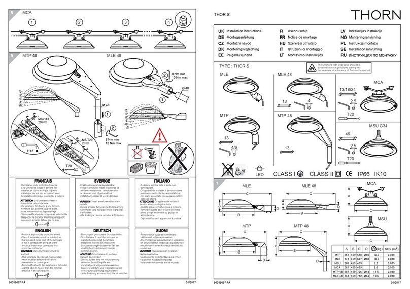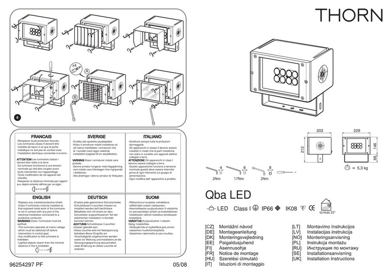
LAMP
INSERTION
!. Check lamp size and voltage are corect,
as
specified on cool wiring box.
2. Do not: remove paper sleeve from lamp.
3.
Open
fitting front
by
releasing spring toggles (on
SOOw.
thumb
screw) on
top
of
the
glazing frame.
4. Release heat sinks
by
rotating heat sink knob towards
the
fitting front.
5. Taking care
to
hold
the
lamp
by
the
paper sleeve at
all
times. insert lamp into lamp-holder
at
one
end, ana
then
into
the
other
lamp-holder.
6.
When
the
lamp
is
in
position, remo
ve
the
paper sleeve
by
tearing off.
7.
Operate
heat sink leyers
to
closed position.
Note:
The glazing frame cannot be properly secured unless this 's
cone.
8.
Close fitting front
a'1c
secure with toggles (on
SOOw.
thu
mb
screw).
9,
Te
st
for insulation and earth continuity, switch on and check
the
alignment.
Important:
If
the
Quartz
lamp
is
unavoidably handled, it is
essential
that
it should be wiped clean
of
grease using a
solvert
such
as
methylated spirit, white spirit. etc.
Because
the
lamp operates at a high
temperatur
e. it
is
important
that
it
sh
ould not be touched until an adequate
co
oling period
has
elapsed, and
in
this respect it should be noticed
that
immediately after switching off, a pinkish glow
within
the
lamp remains. This indicates
that
the
Halogen
is
cooling down and
the
lamp wall
temperature
will be
too
high
to
be touched.
When
this glow disappears
the
lamp can
then
be removed.
If
it
is
intended
to
replace
the
!a,np
a clean cloth
or
protective gloves should be worn.
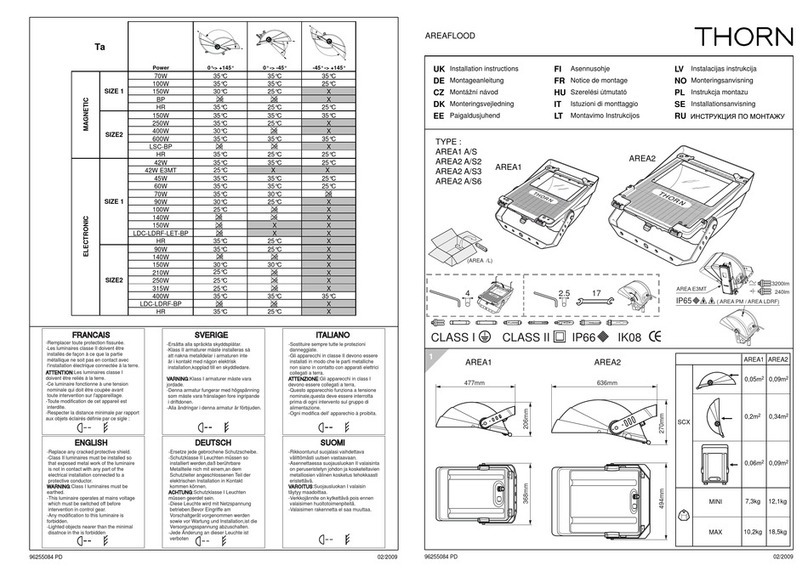
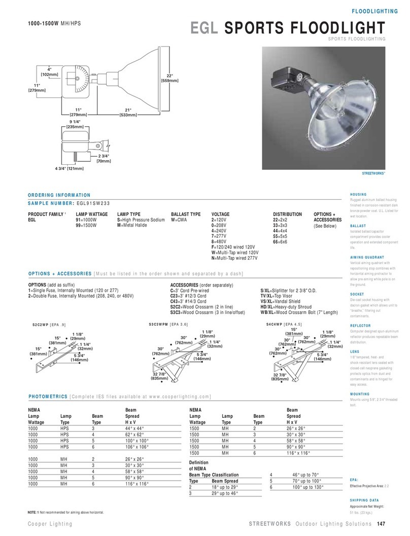
ATIACHMENT
OF
ACCESSORIES
I.
Pole
top
mounting
(HA
4600)
(a)
Fitting
is
attached
to
spigot cap
by
means ofr hexagon bush. (b) Spigot
cap
is
then slid over
the
pole
top
and secured
by
tightening
the
three
Allen screws.
2.
Multi-usemounting(HA4601)
(a)
Wall
and
floor
mounting-attach
mounting
to
wall
or
floor. Secure
fitting
by
means of
the
conduit bush provided. Aim
and tighten. Final leveling
of
lamp
is
facilitated
by
the
slotted fixing hole
in
the
mounting.
(b)
Pole
mount
-
ing-attach
HA
4601
mountingto
pole with
two
'U'
Clamps (HA 4602). Secure fitting
by
means of
the
conduit bush provided.
],
Cross-arm
mounting
(HA
4603)
(a)
Secure brack
et
to
cross-arm with
two
'U'
clamps, (HA
4602).
(b) Attach fittings
to
bracket with bushes provided.
4.
Fioo
!"
mO!.l
oti;;g
(HA
4604).
(a)
Fitting
is
attached
to
spigot
caD
hi
me2.ns
of
tn=
:£"
hexagon bush.
(b) Place spigot cap on base.
Aim
floodlight
in
desired direction then
tig~
ten
Ailen screws under
flan
ge.
S.
Hood
(HA
4605&8)
and
wing
(HA
4(09).
(a)
Hood
·--remove
bottom
sere'", from each side,
po,sitton hood ;wd lightly tighten screws. Remove
the
top
sC
f'ewsa
1
:gn attachment. and
fix.
Tighten
al!
four
sc
rews. (b) 'INing--
-Remc.1Ve
bottom screw from one
side. position wi
ng
and lightly tighten screw. Remove
the
top
screw, align wing and fix, tightening both
screws. Repeat procedure for
other
wing.
Note:
Do
not
release both screws
at
the
same time.
~MP(Hni~T
'---,
!
ay
intsl'llatiol!al agreement wiring colours I
arro
to be:
Uve·BI'Qwn
. Neutra!·Blu!!. Earth· I
~rean
and
iteli!)w.
I
During
Interim period they
may
be: live-tied.
~~~ti'~~la~~_~~~~en.
____
.J
F=E0,
\
"~4~
I
~/
:
~~~-=-='
i
.
--'~
.
,
.....
:
:--,........---1
\...)
./~
--~
H.A
460~
IlING
HA
4609
1'1.69
