Thunder Power TP1430C Installation instructions manual
1
SINGLE PORTHIGH-POWER MULTI-CHEMISTRY
CHARGER/DISCHARGER/CYCLER/BALANCING SYSTEM
INSTRUCTION/OPERATION MANUAL
www.ThunderPowerRC.com

2
TABLE OF CONTENTS
NOTICE, WARNING, AND CAUTION......................................................................................................................... 3
NOTICE ................................................................................................................................................................ 3
WARNING............................................................................................................................................................ 4
CAUTION.............................................................................................................................................................. 4
BOX CONTENTS ....................................................................................................................................................... 4
FEATURES................................................................................................................................................................ 5
SPECIFICATIONS ...................................................................................................................................................... 7
INPUT POWER SOURCE AND CONNECTION............................................................................................................ 6
Input Current Max............................................................................................................................................... 6
Input Power Low Voltage Cutoff......................................................................................................................... 6
Input Power Source Connection ......................................................................................................................... 6
INPUT AND OUTPUT POWER .................................................................................................................................. 7
BATTERY CONNECTIONS ......................................................................................................................................... 7
BALANCER CONNECTIONS (for LiPo/LiIon/LiFe batteries) ...................................................................................... 8
OPERATING INFO..................................................................................................................................................... 9
Button Functions................................................................................................................................................. 9
+/–buttons.......................................................................................................................................................... 9
PORT button..........................................................................................................Error! Bookmark not defined.
MODE button ...................................................................................................................................................... 9
ENTER button...................................................................................................................................................... 9
CHARGE MODE...................................................................................................................................................... 10
Memory Profiles................................................................................................................................................ 10
Battery Chemistry Type..................................................................................................................................... 10
Battery Cell Count ............................................................................................................................................. 11
Battery Capacity................................................................................................................................................ 11
Charge Current Rate.......................................................................................................................................... 11
Balancing ON/OFF (for LiPo/LiIon/LiFe batteries)............................................................................................. 12
Delta Peak Sensitivity (for NiCd/NiMH batteries)............................................................................................. 13
Charging the Battery ......................................................................................................................................... 13
Charging LiPo/LiIon/LiFe (A123) Batteries ........................................................................................................ 13
Data Monitoring During Charging..................................................................................................................... 14
Charging Complete/End.................................................................................................................................... 15
Charging LiPo Batteries for use in Series on Separate Ports.................................Error! Bookmark not defined.
Charging Split LiPo Batteries up to 16S on Separate Ports ...................................Error! Bookmark not defined.
DISCHARGE MODE ................................................................................................................................................ 15
Discharge Current Rate ..................................................................................................................................... 16
Discharge Voltage Cutoff................................................................................................................................... 17
Discharging the Battery..................................................................................................................................... 17
Data Monitoring During Discharging................................................................................................................. 17
Discharging Complete/End................................................................................................................................ 18
Cooling Fans During/After Discharge................................................................................................................ 18

3
CYCLE MODE ......................................................................................................................................................... 18
Cycle Order........................................................................................................................................................ 18
Cycle Number.................................................................................................................................................... 18
Cycling the Battery............................................................................................................................................ 19
Data Monitoring During Cycling........................................................................................................................ 19
Cycling Complete/End....................................................................................................................................... 19
STORAGE MODE.................................................................................................................................................... 20
Storage Charging/Discharging the Battery........................................................................................................ 20
Data Monitoring During the Storage Process ................................................................................................... 20
Storage Complete/End...................................................................................................................................... 21
SETTING DATA MODE............................................................................................................................................ 21
Charge End Voltage........................................................................................................................................... 21
Power Distribution ................................................................................................Error! Bookmark not defined.
Input Power LVC/Input Current Max ................................................................................................................ 22
Cycle Pause Time............................................................................................................................................... 22
Charge Capacity Limit........................................................................................................................................ 22
Safety Timer ...................................................................................................................................................... 23
Temperature Cutoff .......................................................................................................................................... 23
Key Beep............................................................................................................................................................ 23
End Beep Duration ............................................................................................................................................ 23
Temperature Unit.............................................................................................................................................. 23
DATA VIEW MODE................................................................................................................................................. 24
Battery Internal Resistance............................................................................................................................... 24
To Measure Battery Internal Resistance........................................................................................................... 25
To Measure Individual Cell Internal Resistance................................................................................................ 26
Charge/Discharge Mode Data........................................................................................................................... 26
Cycle Charge/Discharge Capacity Data ............................................................................................................. 26
Peak Voltage and Discharge Average Voltage Data.......................................................................................... 26
Individual Cell Voltage Data (for LiPo/LiIon/LiFe Batteries).............................................................................. 27
Real-Time Input Voltage and Output Voltage Data .......................................................................................... 27
Internal Temperature Data ............................................................................................................................... 27
ERROR MESSAGES AND TROUBLESHOOTING ....................................................................................................... 27
FIRMWARE UPDATES ............................................................................................................................................ 28
WARRANTY, SUPPORT, AND SERVICE................................................................................................................... 29
NOTICE

4
All instructions, warranties, and other collateral documents are subject to change at the sole discretion
of Advance Energy, Inc. dba Thunder Power RC. For up-to-date product literature, visit
www.ThunderPowerRC.com or call 702-228-8883.
WARNING
Read the ENTIRE instruction manual to become familiar with the features/functions of the
charger before operating. NEVER LEAVE THE CHARGER UNATTENDED DURING USE. Failure
to observe/operate the charger properly can cause damage to the charger, battery, personal
property and/or cause serious injury.
CAUTION
Attempting to charge batteries different than those specified in this manual can result in excessive
heat and other related product malfunctions, which can lead to property damage and/or injury. Please
contact Thunder Power RC (TPRC) or an authorized retailer with compatibility questions.
As TPRC has no control over use, setup, final assembly, modification or misuse, no liability shall be
assumed nor accepted for any resulting damage or injury. By the act of use, setup or assembly, the
user accepts all resulting liability.
If you as the Purchaser or user are not prepared to accept the liability associated with the use of this
Product, you are advised to return this Product immediately in new and unused condition to the place
of purchase.
BOX CONTENTS

5
FEATURES
Powerful all-in-one charger, discharger and cycler system with built-in LiPo/LiIon/LiFe (A123) cell
balancer that offers maximum safety, performance and easy-to-see individual cell voltages
The included balance connector adapter board allows the built-in balancer to be used with 2-14S
Thunder Power-compatible balance connectors as well as the JST-XH balance connectors found
on many other brands of batteries. This powerful single port design charges, discharges and
cycle’s 1-14S LiPo/LiIon/LiFe (A123), 1-40 cell NiCd/NiMH or 6-48V Pb (lead-acid) batteries.
Up to 1000 watts of total power with selectable charge current between 0.2 amps up to 30 amps
for ultra-fast charging
The perfect choice for safe and ultra-fast charging at rates of up to 6C and beyond for the latest-
generation LiPo batteries
Advanced Storage Mode function for LiPo/LiIon/LiFe (A123) batteries will automatically charge or
discharge as needed to achieve storage level voltage
12 user-programmable memories plus built-in live data monitoring with internal resistance
measurement, battery voltage, input voltage, temperature and more
Fully-adjustable charge capacity limit, per cell end voltage and low voltage cutoff settings for all
chemistries to maximize safety, charge and discharge performance
Durable and compact aluminum case with dual computer-controlled cooling fans and a large,
easy-to-read LCD screen
Wide input voltage range from 12.0-36.0V for higher efficiency and power output when using 24.0-
36.0V power supplies
Adjustable input power current limiting and low voltage cutoff settings to maximize performance
while also protecting the charger and input power supply
Future firmware updates can be downloaded for free from www.ThunderPowerRC.com when new
features, battery chemistry and other updates are made available and are easily uploaded to the
charger using a standard mini USB cable
Full industry-leading warranty and support from Thunder Power RC
SPECIFICATIONS
Type: Multi-Chemistry DC Charger/Discharger/Cycler with Integrated Balancers
Battery Cell Counts/Types: 1-14S LiPo/LiIon/LiFe (A123), 1-24 cell NiCd/NiMH and 6-30V Pb (lead-
acid)
Balancer: Integrated for 2-14S LiPo/LiIon/LiFe (A123) with balance connector adapter board for
Thunder Power and JST-XH connectors
Input Power: 12.0-36.0V DC (40 amps max)
Charge Power: 1000 watts max w/28.0-36.0V input (see later in this manual for additional information
regarding input and output power)
Charge Current 0.2 to 30 amps in 0.01 amp increments
Charge Voltage: 50% storage and adjustable end voltage for LiPo/LiIon/LiFe (A123), adjustable delta
peak sensitivity and end voltage for NiCd/NiMH and end voltage for Pb (Lead Acid)

6
Discharge Power: 100 watts max
Discharge Current: 0.2 to 15 amps in 0.01 amp increments
Discharge Voltage: Adjustable low voltage cutoff for LiPo/LiIon/LiFe (A123), NiCd/NiMH and Pb
(lead-acid)
Cycles: 1 to 15 times
Memories: 12 user-programmable
Firmware: User-updatable using USB
INPUT POWER SOURCE AND CONNECTION
The TP1430C (charger) is designed and built to be powered from a 12.0-36.0V DC power source.
This can include a single 12V Pb/lead-acid battery, three 12V Pb/lead-acid batteries connected in
series for up to 36V or a quality AC to DC power supply with stable 12.0-36.0V DC output.
Input Current Max
The maximum input current can be set from 10.0-40.0A in order to prevent damage to the power
source and/or charger. This means you can limit the maximum current the charger can pull from the
power source per the maximum capabilities of the source as needed. For example, if you are using a
power supply that is capable of outputting 25.0A max you should adjust the Input Current MAX setting
to 25.0A to ensure the charger is not able to pull more than 25.0A from the power supply. You can
adjust this setting in the charger by powering it on and pressing the MODE button once to scroll to the
Setting Data Mode menu, then press the + or –buttons to scroll to the appropriate menu and adjust
the setting accordingly. Or, in order to obtain maximum output power (per input voltage) for charging,
you must use a power supply capable of delivering up to 40.0A.
Input Power Low Voltage Cutoff
You can also set the Input Power LVC (Low Voltage Cutoff). This is the input voltage at which the
charger will stop charging/discharging in order to prevent overloading/over-discharging the input
power source. This is particularly beneficial when charging from a 12V Pb/lead-acid car battery as it
allows you to maintain enough voltage/power in the battery to still start the car after using the charger.
You can adjust this setting in the charger by pressing the MODE button once to scroll to the Setting
Data (Settings) menu, then press the + or –buttons to scroll to the appropriate menu and adjust the
setting accordingly. We recommend setting this value to between 12.0V and 13.0V for typical use, or
in the case that you will be loading the input power source considerably (so the voltage will drop more
significantly under load even though there is still sufficient capacity remaining in the 12V battery for
example) you can set this as low as 12.0V. However, keep in mind that dropping the voltage under
load to as a low as 12.0V (or even 13.0V under some loads) could result in discharging a 12V battery
input power source low enough that it will not start the car when needed.
Input Power Source Connection
The input power leads for the charger are equipped with 4mm bullet connectors compatible with most
typical female ‘banana plug’ receptacles. You can connect these directly to the outputs of many AC to
DC power supplies, or you can also connect them to the included alligator clips for more convenient
connection to Pb/lead-acid batteries. However, especially when charging at or near maximum
input/output power levels, you must ensure the bullet connectors/alligator clips are making excellent
contact with the power source in order to minimize resistance and prevent voltage/power
loss/damage.

7
After connecting the charger to the input power source with proper polarity the charger will power on
accordingly. At this point you will briefly see the ‘Welcome’ screen indicating the charger model and
the version of firmware currently installed in the charger.
Please also note that in some cases if the connection to the input power source is not ‘clean’
the welcome screen may not show and instead only part of the default Charge Mode screen
will show. This will typically happen when connecting the charger to a power source that is
already ‘on’ so we suggest powering down the source before connecting the charger. Also, if
this occurs simply disconnect the charger from the power source, then re-connect ensuring
that you achieve a solid/clean connection during the process.
INPUT AND OUTPUT POWER
The charger will automatically adjust the max output power level available based on the input voltage,
current, output voltage, etc. and at no time can the input current exceed 40.0A max. As a result you
can obtain higher/maximum output power when using higher voltage power sources that provide 24.0-
36.0V. However, it is still possible to obtain relatively high levels of output power using more common
12.0-15.0V power sources.
Here also is a quick way to help determine the approximate amount of input power your chosen power
source can supply:
Input Voltage (under load) (V) x Input Current (A) = Input Power (W)
For example:
12V x 25A = 300W
12V x 40A = 480W 24V x 25A = 600W
27V x 40A = 1080W
The input power level will dictate the charger’s output power level capability in total based on charger
efficiency (typically ~85-93% depending on input/output voltage). And in turn the output power level
capability will dictate the maximum charge current/voltage capability accordingly.
Please see the chart provided separately for a quick reference of the maximum output power
levels/charge current for LiPo batteries based on the listed input voltage and current (and please note
that these values are approximate and may vary slightly +/–depending on input voltage of the power
source under load, ambient temperatures, state of charge/voltage level of the battery being charged,
etc.).
Also, for those interested in achieving maximum output power (1000W total) we recommend using a
27.0-28.0V, 35-40A power supply for maximum efficiency (especially when charging multiple 6S
22.2V LiPo batteries for example). One such power supply we’ve used with excellent success is the
IOTA Engineering DLS-27-40. With a typical output voltage of 27.2V and the capability to deliver up
to 40A, this power supply can deliver upwards of 1100W to the charger allowing for maximum output
(1000W) with some headroom to spare (also works well with two TP1430C chargers running at high
power levels up to ~500W each).
BATTERY CONNECTIONS

8
The charger is equipped with typical female ‘banana plug’ receptacles that are compatible with most
male banana plugs and 4mm bullet connectors. We suggest using gold 4mm bullet connectors, like
those found on the included battery connection leads, especially when charging at rates above 5
amps.
You can also install the connector of your choice on the included battery connection leads or you can
purchase pre-made ‘charge leads’ equipped with banana or 4mm bullet connectors and connectors
compatible with the connectors installed on the batteries you will be charging/discharging. Please
note that wire leads that are too long or not large enough gauge for the applicable charge/discharge
current will damage the charger and/or result in errors in battery charging/discharging. Therefore we
recommend keeping the length of the wire leads as short as possible (preferably 12”/305mm long
max). We also recommend using 10 to 14 AWG wire leads when charging at rates 10 amps and
higher, minimum 16 AWG at rates up to 10 amps and minimum 18 AWG at rates up to 5 amps.
Please also be certain to connect all batteries with the proper polarity as marked on the faceplate
label and further identified by the colored rings around the banana plug receptacles (red is +/positive
and black is –/negative). And in the event that you do connect the battery with incorrect polarity the
error message ‘Battery Reverse Polarity’ (or ‘Battery Polarity Inversion’ in earlier version firmware) will
show on the screen. However, in order to prevent all possibility of damage to the charger and/or
battery you should always exercise care to ensure proper polarity when connecting batteries.
Also, DO NOT connect the battery to the charger when the charger is powered off. The
charger should always be powered on before connecting the battery.
BALANCER CONNECTIONS (for LiPo/LiIon/LiFe batteries)
The TP1430C is equipped with built-in balancer for LiPo/LiIon/LiFe (A123) cells/batteries. The
balancer is marked on the faceplate label and you must ALWAYS use the balancer when charging
LiPo/LiIon/LiFe batteries for maximum safety and battery performance/longevity. The balancer
works in conjunction with the charger to prevent over-charging that can result in fire causing
damage and/or personal injury. It does this by ensuring the voltages of cells within LiPo/LiIon/LiFe
batteries are closely balanced by discharging the higher voltage cells to closely match the lower
voltage cell(s) in the battery. This prevents over-charging any cell(s) that may have a higher voltage
during the charge process, or, in the event that the balancer cannot balance the cell(s) in time to
prevent exceeding the ‘CHG End Voltage’ setting (for any cell), the charger will automatically reduce
the charge current rate and/or end the charge process entirely as needed.
Please also note that due to the high-power charging capabilities of the TP1430C, it is not
designed to charge through the balance connectors/leads of LiPo/LiIon/LiFe batteries. These
connectors/leads are typically limited to maximum charge/discharge rates of only 2-4 amps
versus the up to 20 amp charge rate capability of the TP1430C. As a result you MUST connect
the main power AND balance connector leads to the charger in order to charge through the
main power and balance through the balance connector leads accordingly.
There is one 8-pin and one 9-pin Thunder Power type connector for the balancer located on the side
of the charger. When viewing each connector straight on (with the top/face of the charger pointed
upwards) the main ground/negative (–) connector (pin) is located on the far left while the positive (+)
connector is located on the far right. In order to prevent any issues with connection location, polarity,
or fatigue of the connection between the 8 and 9-pin connectors and the charger board internally, you
must always use the included balance connector adapter board.
To use the included balance connector adapter board simply insert the male 8 and 9-pin connectors
into the female 8 and 9-pin connectors on the side of the charger. The connectors are ‘keyed’ to
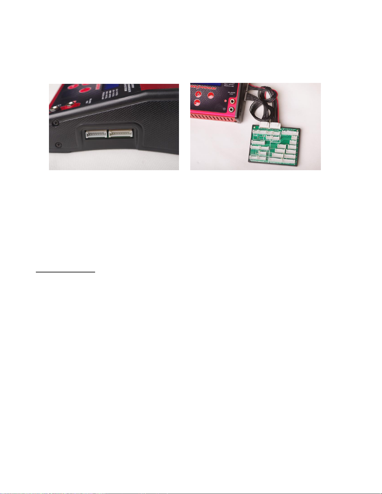
9
prevent reverse polarity connection, and each balance connector adapter board is equipped with
balance connectors compatible with all 2S 7.4V to 14S 51.8V LiPo/LiIon/LiFe batteries equipped with
Thunder Power and JST-XH balance connectors. And in the event that you must connect batteries
that are not equipped with TP or JST-XH balance connectors, there are additional balance connector
adapter leads (i.e. –TP to JST-EH, etc.) available from many sources.
After connecting the balance connector adapter board to the charger/balancer you can connect the
balance connector from the battery to the appropriate mating connector, ensuring proper keying of the
connectors and polarity on the board accordingly. And please note that unless you are using the
correct adapters/connections to charge multiple batteries in series and/or parallel (contact Thunder
Power RC directly for more information on series/parallel charging if needed) you must NOT connect
more than one battery to the balance connector adapter board. If you connect multiple batteries
incorrectly or connect one battery with incorrect polarity it is possible to damage the traces and/or the
pins/connectors on the balance connector adapter board. Such damage is not covered under
warranty.
OPERATING INFO
Button Functions
+/–buttons
The +/–buttons allow you to scroll up/down through menus before and during charging/discharging.
These buttons also allow you to change values/settings for options after they have been selected
(typically when flashing after pressing the ENTER button).
MODE button
The MODE button functions only before and not during charging/discharging. Pressing the MODE
button will allow you to scroll between the three available modes:
Charge/Discharge/Cycle/Storage Modes
Setting Data Mode
Data View Mode
ENTER button

10
The ENTER button allows you to select and validate values/settings for options that can be changed
(using the +/–buttons to change) before and during charging/discharging. Pressing and holding the
ENTER button also allows you to start and stop charging/discharging.
CHARGE MODE
After powering on the charger properly the first mode always shown by default is the ‘Charge Mode’.
This is the mode that allows you to set the memory profile number, battery chemistry type, number of
cells, battery capacity limit, charge current rate, balancing on/off for LiPo/LiIon/Life or the delta peak
value for NiCd/NiMH. It’s also important to note that all of these settings must be set in this
mode/screen before changing to the discharge, cycle or storage modes (these settings cannot
be changed/set in those modes).
Here is a quick reference of what the Charge Mode screen displays:
Memory Profiles
You can set a total of 12 memory profiles. This is a convenient feature as it allows you to set the
typical charge, discharge, cycle, and storage mode profiles for specific batteries to save you time
versus having to always change the settings when charging/discharging different configurations and
chemistries of batteries.
To scroll through the available memory profiles, while on the Charge Mode screen simply press the
ENTER button once. The memory profile number will begin to flash and you can use the +/–buttons
to scroll through the profiles accordingly.
Battery Chemistry Type
The TP1430C is capable of charging/discharging LiPo, LiIon, LiFe (A123), NiCd, NiMH and Pb (lead-
acid) batteries. Each of these chemistries/types of batteries is charged in a different way and
the correct chemistry/type must be selected in order for the charger to charge/discharge
safely. Failure to select the correct chemistry/type and settings per the battery being
charged/discharged can result in damage to the battery or fire causing damage and/or
personal injury. If you are unsure of the battery chemistry/type, and the correct settings that
must be used for safe and correct charging/discharging, DO NOT attempt to charge/discharge
the battery. Instead, please contact the manufacturer of the battery to verify the information
prior to charging/discharging the battery.
To select the correct battery chemistry/type, while on the Charge Mode screen simply press the
ENTER button twice. The battery chemistry/type will begin to flash and you can use the +/–buttons to
scroll through them accordingly. After selecting the correct chemistry/type you can press the ENTER
1) Memory profile number
2) Battery chemistry type
3) Mode (charge, discharge, cycle, storage)
4) Number of cells (in series)
5) Battery capacity
6) Current rate
7) Balancing ON/OFF for LiPo/LiIon/LiFe or
Delta Peak Sensitivity value for NiCd/NiMH

11
button to select the other adjustable values, or wait approximately 5 seconds until the chemistry/type
stops flashing to begin the charge process or to scroll through the other modes (discharge, cycle, and
storage).
Battery Cell Count
The TP1430C is capable of charging/discharging 1S (3.7V) to 14S (51.8V) LiPo, LiIon and LiFe
(A123) batteries, as well as 1-40 cell NiCd and NiMH along with 1S (2V) to 24S (48V) Pb (lead-acid)
batteries. After selecting the correct battery chemistry/type you MUST select the correct cell
count for the battery you will be charging/discharging. Failure to select the correct cell count
per the battery being charged/discharged can result in damage to the battery or fire causing
damage and/or personal injury. If you are unsure of the battery cell count DO NOT attempt to
charge/discharge the battery. Instead, please contact the manufacturer of the battery to verify
the information prior to charging/discharging the battery.
To select the correct battery cell count, while on the Charge Mode screen simply press the ENTER
button three times. The battery cell count will begin to flash and you can use the +/–buttons to
increase/decrease the cell count accordingly. After selecting the correct cell count you can press the
ENTER button to select the other adjustable values, or wait approximately 5 seconds until the cell
count stops flashing to begin the charge process or to scroll through the other modes.
Battery Capacity
For added safety and ease of use, the TP1430C features a function that allows you to set the battery
capacity. This function allows you to enter the capacity of the battery you’ll be charging so the
charger can automatically set a 1C (1 x Capacity) charge rate. In general most supported battery
chemistries/types can be charged safely and successfully at a 1C rate, so this feature makes for the
easiest possible setting and use especially if you are not confident in taking advantage of and/or
aware of the max charge rate capability of the battery you’ll be charging.
ALWAYS set the battery capacity correctly. To set the correct battery capacity, while on the
Charge Mode screen simply press the ENTER button four times. The battery capacity will begin to
flash and you can use the +/–buttons to increase/decrease the capacity accordingly. After setting the
correct capacity you can press the ENTER button to select the other adjustable values, or wait
approximately 5 seconds until the battery capacity stops flashing to begin the charge process or to
scroll through the other modes.
Charge Current Rate
After setting the battery capacity limit correctly, the charger will automatically set the charge current
rate to 1C. In the case of a 5000mAh battery, it will set the charge current to 5.00A. And again, in
general most supported battery chemistries/types can be charged safely and successfully at a 1C rate
so we suggest charging at the 1C rate especially if you are not confident in taking advantage of and/or
aware of the max charge rate capability of the battery you’ll be charging.
Or, if you are interested in charging at a rate higher (or lower) than 1C you can adjust the charge
current rate accordingly. However, it is important to note that if you charge at a current rate that
is too high it can result in damage to the battery or even fire causing damage and/or personal
injury. If you are unsure of the maximum safe charge rate of the battery, DO NOT charge at a
rate higher than 1C or please contact the manufacturer of the battery to obtain the correct
maximum charge rate.

12
To set the charge current rate: while on the Charge Mode screen simply press the ENTER button five
times. The charge current rate will begin to flash and you can use the +/–buttons to
increase/decrease the current rate accordingly. After setting the charge current rate you can press
the ENTER button to select the other adjustable values, or wait approximately 5 seconds until the
current rate stops flashing to begin the charge process or to scroll through the other modes.
Also, before starting the charge process, the maximum charge current that can be set is
automatically calculated by the charger based on the voltage of the input power source and
the estimated voltage of the battery being charged based on the cell count you have selected.
This is calculated using the discharged voltage of the battery (i.e. ~3.3V per cell for LiPo batteries),
but will be no higher than 30A as this is the maximum charge current.
If you have set the charge current rate to the maximum rate possible, after starting the charge
process the charger will automatically adjust the current rate, per the actual voltage of the
battery at any given time, to maintain (and not exceed) the maximum output power level
(wattage). For example, in the case of charging a 6S 22.2V 5000mAh LiPo battery and when using a
27.0-36.0V/35-40A power supply for maximum input/output power, before the charge process has
started you will be able to set the charge current rate to 30.0A max. However, if the battery is
currently at more than 20.0V the charger will then adjust the current rate automatically between 30.0A
and approximately 15.8A as needed to ensure it does not exceed the 1000W maximum output power
level. And when the battery nears/reaches the end of the Constant Current (CC) phase of the charge
around 25.2V (4.2V per cell) the current rate will reduce accordingly throughout the Constant Voltage
(CV) phase of the charge process and until the charge is complete.
Also, after the charge process has started (and if you have not already set the charge current
rate to the maximum rate possible) you can actually increase the charge current rate by up to
25% (i.e. –from 10.0A to 12.5A) or to the maximum charge current rate possible based on the
actual voltage of the battery and output power level of the charger; whichever comes first. To
do this, simply press the ENTER button once immediately (or any time) after the charge process has
been started (and the ‘Battery Check Please Wait…’ check is complete) and the current rate will begin
to flash. You can then use the + button to increase (or the –button to decrease) the current rate
accordingly.
Please also see the chart provided separately for a quick reference of the maximum output power
levels/charge current rate settings for LiPo batteries based on the listed input voltage and current
(please note that these values are approximate and may vary slightly +/-).
Balancing ON/OFF (for LiPo/LiIon/LiFe batteries)
As noted in further detail in the BALANCER CONNECTIONS section of this manual, the TP1430C is
equipped with built-in balancer for LiPo/LiIon/LiFe (A123) cells/batteries and you must ALWAYS use
the balancer when charging LiPo/LiIon/LiFe batteries for maximum safety and battery
performance/longevity.
The balancer can also further ensure that you’ve set the cell count correctly, and as a result
we strongly recommend keeping the balancing turned ON at all times. Please also note that
when balancing is turned ON you MUST connect the balance connector of the battery to the
balance connector adapter board (which must be connected to the balancer/charger) BEFORE
you start the charge process otherwise you’ll encounter a Battery Type Error warning.
However, if you understand the associated risks, accept full responsibility, and choose to charge
LiPo/LiIon/LiFe batteries without balancing/using the built-in balancers, it is possible to turn the
balancing OFF.

13
To turn the balancing ON/OFF, while on the Charge Mode screen simply press the ENTER button six
times. The balancing status will begin to flash and you can use the +/–buttons to turn it ON or OFF.
After turning the balancing ON or OFF you can press the ENTER button to select the other adjustable
values, or wait approximately 5 seconds until the status stops flashing to begin the charge process or
to scroll through the other modes.
Delta Peak Sensitivity (for NiCd/NiMH batteries)
When the charger has been set to charge NiCd or NiMH chemistry/type batteries you can also set the
delta peak sensitivity value. This is the difference in voltage when the NiCd/NiMH battery reaches
peak voltage/fully charged voltage and is used to complete/end charging of NiCd/NiMH batteries
accordingly.
Generally speaking a higher delta peak sensitivity value will result in more charge or even potential
over-charge, however, in many cases a slight amount of over-charge and the resulting warming of the
cells/battery is desired to ensure the highest possible performance. Slightly warm NiCd/NiMH
cells/batteries (approximately 5-15° Fahrenheit above ambient) are also a good indication that they
are fully charged, however, it is recommended to use the lowest delta peak sensitivity value that
allows the cells/battery to be fully charged and to not stop charging prematurely (typically referred to
as ‘false peaking’).
NiCd cells/batteries typically require a higher delta peak sensitivity value (~10-20mV per cell) to reach
full charge while NiMH batteries require a lower value (~1-10mV per cell). However, in the case of
either chemistry the actual value that works best will depend on many factors including the capacity,
condition and internal resistance (IR) of the cells/battery, IR of the charge leads/connectors, charge
current rate, ambient temperature and more. As a result it is always suggested to start with a lower
value and to increase the value accordingly as needed to achieve slight warming of the cells after the
charge process had been completed/ended.
To adjust the delta peak sensitivity value, while on the Charge Mode screen simply press the ENTER
button six times. The value will begin to flash and you can use the +/–buttons to increase or
decrease the value accordingly. After setting the value per your preference you can press the ENTER
button to select the other adjustable values, or wait approximately 5 seconds until the value stops
flashing to begin the charge process or to scroll through the other modes.
Charging the Battery
After setting the correct battery chemistry type, cell count, capacity, and current, and connecting the
battery to the charger properly, you are ready to begin charging. To begin charging simply press and
HOLD the ENTER button for a few seconds (please also note that during charging you can press and
hold the ENTER button to end the charge process).
If the battery is connected properly and the charger confirms that all other parameters are correct,
charging will begin automatically.
Charging LiPo/LiIon/LiFe (A123) Batteries
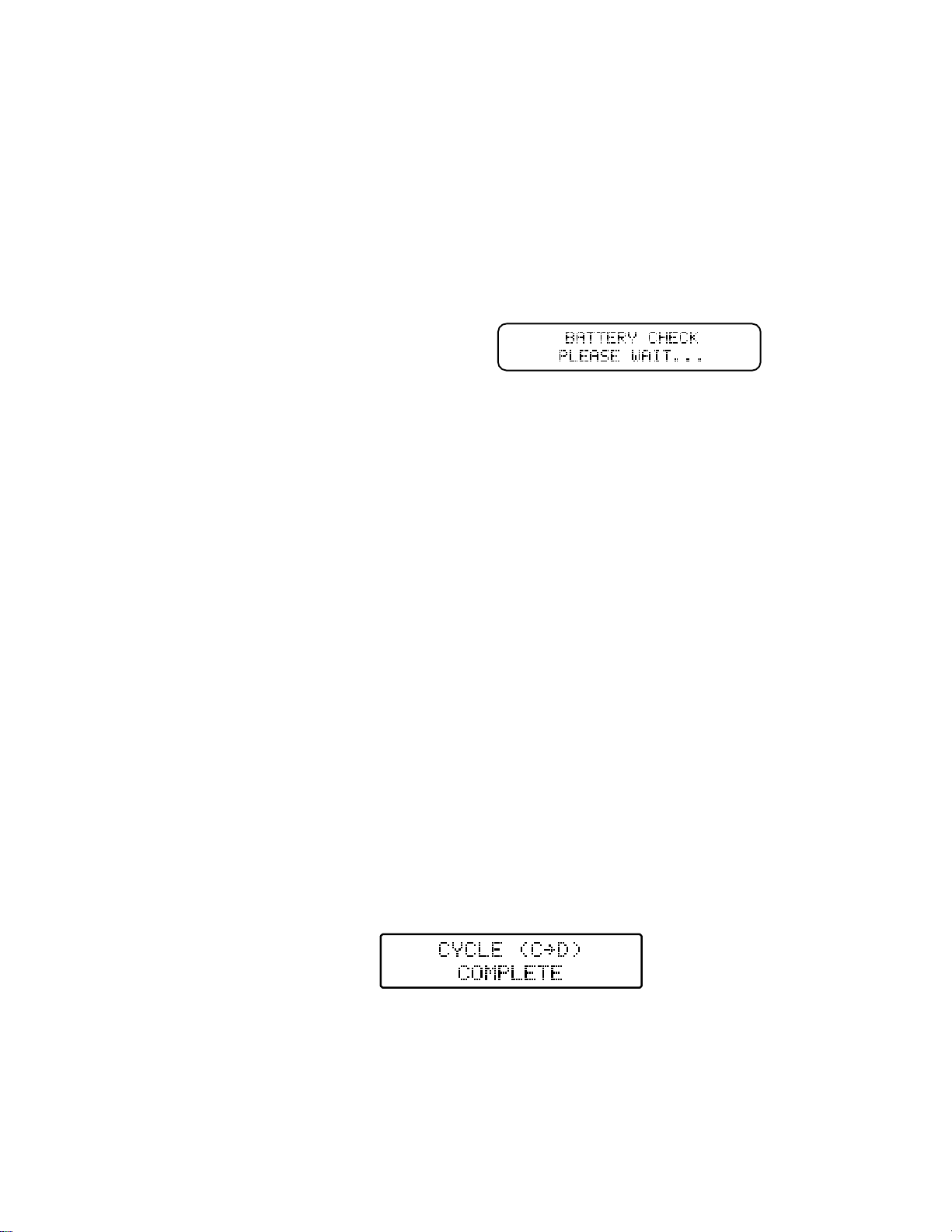
From there the charger will check the battery
while displaying the following screen:

14
When charging LiPo/LiIon/LiFe batteries, if the voltage of any cell (when balancing is ON) or all cells
are too low (below ~3.3V) the charger may charge at a rate lower than the charge current rate set
before the charge process began and until the voltage is considered safe/high enough to charge the
battery normally. Or, if the voltages of all cells are OK the charger will increase the current until it
reaches the appropriate charge current rate. And in either case charging will be in the Constant
Current phase, as indicated by the ‘CC’ located in the middle of the upper line on the screen, until the
cells reach approximately 4.20V.
At that point, and as long as cells are balanced within 0.03V (when balancing is ON), charging will
switch to the Constant Voltage phase as indicated by the ‘CV’ that will show in placed of ‘CC’. Or, if
any cell is imbalanced by more than 0.03V charging will instead switch from the Constant Current
phase to the Extended Balance phase, as indicated by the EB that will show in place of CC/CV. This
will allow the charger to adjust the charge current rate as needed to ensure the cells are balanced to
within 0.03V (or closer) before the charge process is ended automatically.
Data Monitoring During Charging
Throughout (and after) the charge process you can view/monitor various data. On the main charging
screen you will see the elapsed duration of the charge process, the capacity that’s been ‘charged’ into
the battery, the charge current rate and the voltage of the battery. You can also use the +/ –buttons
to switch between the various screens to see the available data.
For example, when charging a LiPo/LiIon/LiFe battery and on the charging screen simply press the +
button once and you will see the individual cell voltages (when balancing is turned ON). Please also
note that while only the second (hundredths) place after the decimal is shown due to the space
available on the screen (in order to show voltages for up to 8 cells on a single screen), the
charger is measuring and calculating the voltages/balance by using to the third (thousandths)
place. This means when you see a cell at 3.80V and another at 3.82V the cells are likely as
close as 3.804V and 3.816V, but the values on the screen are being rounded up and down
accordingly.
If you press the + button a second time you’ll again see the elapsed time, as well as the internal
temperature of the charger and the peak voltage the battery has reached through the duration of the
charge process so far. Then, pressing the + button a third time will show the elapsed time along with
the input voltage from the power source. This can be particularly useful, especially when pushing the
input power source near its limits and/or when using a 12V (or 24V) Pb/lead-acid battery, to ensure
the voltage is not dropping too much when under load during the charging process. Please also note
that while only the second (hundredths) place after the decimal is shown the charger is measuring
and calculating the input voltage by using to the third (thousandths) place. This means the input
voltage reading may appear to move up and down slightly, however, as long as it is not fluctuating by
more than ~0.03V the input voltage/power is indeed smooth and stable.
When charging a NiCd/NiMH/Pb (lead-acid) battery, the first time you press the + button you will see
the elapsed time along with the average voltage of the battery that would show after a discharge
process has ended. Pressing the + button a second time will show the internal temperature of the
charger and the peak voltage the battery reached during the charge process, while pressing the +
button a third time will show the elapsed time along with the input voltage from the power source.
Prior to charging, please review the Charge End Voltage information under the SETTING DATA
MODE section found later in this manual.

15
Charge Completion
Charging will end automatically when the battery capacity has been reached per delta peak (for
NiCd/NiMH batteries) or when the appropriate per cell CHG (Charge) End Voltage has been reached
(for LiPo/LiIon/LiFe and Pb batteries). When this occurs you will see the following screen:
From there you can press the ENTER button once to display the data from the charge process, as
well as use the +/ –buttons to scroll through other screens, including the screen that features the
Battery IR function to check the Internal Resistance (IR) of the battery and/or individual cells by
pressing the ENTER button (while on those screens). Or, on most other screens you can press the
ENTER button to exit the charge process completely.
Charging LiPo Batteries in Series
The 1430C balance adapter board will allow you to charge up to two 7S batteries or any combination
to make a maximum of 14S at one time. Example: Two 6S batteries, Insert the balance plugs from
battery 1 in the first set of plugs marked 6S. Then insert the balance plugs from battery 2 in the
second set of 6S plugs. The charger will now read this as a single 12S battery. Then you need to
attach a battery series charge adapter wire to the main power wires of the battery. Always connect the
negative wire from the charger directly to battery number one. Make sure you set the charger for the
appropriate numbers of cells.
DISCHARGE MODE
The TP1430C is able to discharge batteries at rates up to 15.0A or 100W in order to check capacity or
for other reasons as needed. . Please keep in mind that aside from the discharge current rate and per
cell voltage cutoff that can be set in the Discharge Mode, the cell count must be set in the Charge
Mode.
After setting the correct cell count in the Charge Mode, wait until none of the adjustable values are
flashing, then press the + button once to enter the Discharge Mode.

16
Discharge Current Rate
In general most supported battery chemistries/types can be discharged safely and successfully at a
1C to 4C rate so we suggest discharging at no higher than these rates especially if you are not aware
of the max discharge rate capability of the battery you’ll be discharging. However, because the
TP1430C is capable of discharging at rates up to 15A/100W, in many cases it will not be possible to
discharge batteries even at the 1C rate, especially those above approximately 3S 11.1V 5000mAh.
However, especially in the case of lower capacity batteries for which you can exceed a 4C
discharge rate, it is important to note that if you discharge at a current rate that is too high it
can result in damage to the battery or even fire causing damage and/or personal injury. If you
are unsure of the maximum safe discharge rate of the battery DO NOT discharge at a rate
higher than 1C to 4C or contact the manufacturer of the battery to verify the battery’s
maximum discharge rate.
To set the discharge current rate, while on the Discharge Mode screen simply press the ENTER
button once. The discharge current rate will begin to flash and you can use the +/–buttons to
increase/decrease the current rate accordingly. After setting the discharge current rate you can press
the ENTER button to select the other adjustable values, or wait approximately 5 seconds until the
current rate stops flashing to begin the discharge process or to scroll through the other modes.
Also, before starting the discharge process, the maximum discharge current that can be set (if
it is less than 15.0A) is automatically calculated by the charger based on the estimated voltage
of the battery being discharged and the cell count you have selected (~3.6V per cell for LiPo
batteries). So in most cases it is not possible to set the discharge current rate to the 15.0A max for
cell counts more than 2S 7.4V for LiPo/LiIon/LiFe, and even if you do set the rate to 15.0A for higher
cell batteries, it will exceed the maximum discharge power level (wattage) capabilities and the charger
will reduce the rate accordingly after the discharge process has started.
After the discharge process has started you can increase the discharge current rate by up to
25% (i.e. –from 5.00A to 6.25A), or up to the maximum discharge current rate possible based
on the actual voltage of the battery and power level of the charger for discharging; whichever
comes first. To do this, simply press the ENTER button once immediately (or any time) after the
discharge process has been started (and the ‘Battery Check Please Wait…’ check is complete) and
the current rate will begin to flash. You can then use the + button to increase (or the –button to
decrease) the current rate accordingly.
In the event that the discharge current rate and voltage of the battery being discharged, as well
as the ambient temperature and internal temperature of charger, result in over-heating the
charger (above ~130° F) during the discharge process, you will see the ‘Over Temperature
Please Wait…000°’ warning including the current internal temperature of the charger. The
charger will automatically pause the discharge until it cools to approximately 100° F, then it
will resume the discharge automatically. Since the discharge current rate and voltage of the
battery may not exceed the maximum discharge power rating of the charger, you may indeed
need to reduce the discharge current rate in order to prevent the over temperature and pause.
Please also see the chart provided separately for a quick reference of the estimated maximum
discharge power levels/discharge current rate settings for LiPo batteries based on the current rate and
estimated voltage of the battery (and please note that these values are approximate and may vary
slightly +/- depending on ambient temperatures, state of charge/voltage level of the battery being
discharged, etc.).

17
Discharge Voltage Cutoff
You can set the per cell voltage cutoff that will end the discharge process automatically by using this
setting. However, especially in the case of LiPo/LiIon/LiFe batteries, it is important that you DO
NOT over-discharge the batteries to a voltage that is too low as it can result in damage to the
battery. If you are unsure of the safe discharge voltage cutoff for the battery, DO NOT
discharge the battery or please contact the manufacturer of the battery to obtain the battery’s
low voltage cutoff level.
Here also are some general suggestions of the per cell voltage cutoff to use for each battery
chemistry/type to prevent over-discharge damage:
LiPo/LiIon 3.3-3.5V per cell when discharged at rates of 1-4C
LiFe 2.6-2.8V per cell when discharged at rates of 1-4C
NiCd/NiMH 0.9-1.0V per cell when discharged at rates of 1-4C
Pb/lead-acid 1.6-1.7V per cell when discharged at rates of 1-4C
Discharging the Battery
After setting the correct battery chemistry type and cell count in the Charge Mode and the correct
discharge current rate and voltage cutoff in the Discharge Mode, connect the battery to the charger
properly and you are ready to begin discharging. To begin discharging simply press and HOLD the
ENTER button for a few seconds (please also note that during discharging you can press and hold the
ENTER button to end the discharge process).
If the battery is connected properly and the charger confirms that all other parameters are correct,
discharging will begin automatically.
Data Monitoring During Discharging
Throughout (and after) the discharge process you can view/monitor various data. On the main
discharging screen you will see the elapsed duration of the discharge process, the capacity that’s
been discharged from the battery, the discharge current rate and the voltage of the battery. You can
also use the +/ –buttons to switch between the various screens to see the available data.
For example, when discharging a LiPo/LiIon/LiFe battery and on the discharging screen simply press
the + button once and you will see the individual cell voltages (when balancing is turned ON). If you
press the + button a second time you’ll again see the elapsed time, as well as the internal
temperature of the charger and the peak voltage of the battery at the beginning of the discharge
process. Pressing the + button a third time will show the elapsed time in addition to the input voltage
from the power source.
When discharging a NiCd/NiMH/Pb (lead-acid) battery, the first time you press the + button you will
see the elapsed time along with the average voltage of the battery that will be shown when the
discharge process has ended. Pressing the + button a second time will also show the internal
temperature of the charger and the peak voltage of the battery at the beginning of the discharge
process, while pressing the + button a third time will show the elapsed time in addition to the input
voltage from the power source.
From there the charger will check the battery
while displaying the following screen:

18
Discharging Completion
Discharging will end automatically when the battery reaches the per cell voltage cutoff set by you.
When this occurs you will see the following screen:
From there you can press the ENTER button once to display the data from the discharge process.
Additionally, the +/–buttons can be used to scroll through other screens, including the screen that
features Battery.IR to check the Internal Resistance (IR) of the battery and/or individual cells (for
LiPo/LiIon/LiFe and with the balancer connected). While on the Battery.IR screen, press the ENTER
button to display the Internal Resistance values. Or, on most other screens you can press the
ENTER button to exit the discharge process completely.
Cooling Fans During/After Discharge
During the discharge process one or both fans may come on at low or high settings to help control the
internal temperature of the charger. In some cases, even after the discharge process has ended the
fans will continue to run even when the internal temp has reached near ambient temperature. If this
happens you can power the charger off then on again and the fans will remain off until the next
charge/discharge process begins.
CYCLE MODE
The TP1430C is capable of charging/discharging batteries automatically by cycling them up to 15
times. This can be particularly useful for testing and/or rejuvenating NiCd/NiMH batteries. Please
note that we DO NOT recommend cycling LiPo/LiIon/LiFe batteries as it comes at great risk
unless you monitor all charge/discharge cycles in person fully and set the discharge cutoff
voltage to a level high enough to prevent over-discharge. Additionally, it has been shown that,
unlike other chemistries such as NiCd/NiMH, it is typically not possible to rejuvenate LiPo/LiIon/LiFe
cells/batteries through charge/discharge cycling.
Please also keep in mind that aside from selecting the order of charge->discharge (CHG->DCHG) or
discharge->charge (DCHG->CHG) and the number of cycles, you must set the chemistry type, cell
count, capacity, and charge current rate in the Charge Mode, and the discharge current rate and the
per cell voltage cutoff in the Discharge Mode. After setting the correct values in the Charge Mode,
wait until none of the adjustable values are flashing, then press the + button once to enter the
Discharge Mode. After setting the correct values in the Discharge mode, wait until none of the values
are flashing then press the + button one more time to enter the Cycle Mode.
Cycle Order
You can select the cycle order, charge->discharge (CHG->DCHG) or discharge->charge (DCHG-
>CHG), by using this setting. To change the order simply press the ENTER button once then use the
+/ –buttons to adjust the order accordingly.
Cycle Number
19
This allows you to set the number of cycles the charger will automatically perform from 1 to 15. To set
the number simply press the ENTER button twice and use the +/ –buttons to adjust the number of
cycles accordingly.
Cycling the Battery
After setting the correct battery chemistry type, cell count, capacity and charge current rate in the
Charge Mode, and the correct discharge current rate and voltage cutoff in the Discharge Mode along
with the cycle order and number of cycles, you are ready to begin cycling. To begin cycling simply
press and HOLD the ENTER button for a few seconds (please also note that during cycling you can
press and hold the ENTER button to end the cycling process).
If the battery is connected properly and the charger confirms that all other parameters are correct,
cycling will begin automatically.
Data Monitoring During Cycling
Throughout (and after) the cycling process you can view/monitor various data. On the main cycling
screen you will see the elapsed duration of the current charge or discharge process, the capacity
that’s been charged into/discharged from the battery, the charge/discharge current rate and the
voltage of the battery.
Also, it will be possible to identify whether the charger is charging or discharging for the current cycle,
as well as the number of the current cycle, by looking at the ‘C00D’ info located in the middle of the
upper line on the screen. When the ‘C’ is flashing the charger is charging, and when the ‘D’ is
flashing the charger is discharging. And the number of the current cycle, 01 through 15, will be
displayed between the C and D accordingly.
You can also use the +/ –buttons to switch between the various screens to see the other available
data. For example, when cycling a NiCd/NiMH battery, the first time you press the + button you will
again see the elapsed time along with the average voltage of the battery that will be shown when the
discharge process has ended. Pressing the + button a second time will also show the internal
temperature of the charger and the peak voltage of the battery during the charge or at the beginning
of the discharge process.
Cycling Completion
Discharging will end automatically when the battery reaches the per cell voltage set by you. When
this occurs you will see the following screen:
From there you can press the ENTER button once to display the data from the cycling process, as
well as use the +/ –buttons to scroll through other screens, and on most other screens you can press
the ENTER button to exit the charge process completely. It’s also important to note that the data from
the completed cycling process can also be viewed in the Data View mode after exiting the process
and before the next charge/discharge process begins.
From there the charger will check the battery
while displaying the following screen:

20
STORAGE MODE
The TP1430C features an advanced Storage Mode that automatically discharges and/or charges the
battery for safe and healthy storage. For added reference you should NEVER store LiPo batteries
at full charge for more than few hours at most and they should be stored at temperatures of
40-75° F whenever possible to prevent swelling and/or loss of performance/capacity. Instead
you should use the Storage Mode to automatically charge or discharge them to approximately
50% capacity (~3.85V per cell), especially if the battery is more than 50% charged and will not
be used in the next few hours.
Please also keep in mind that you must set the chemistry type, cell count, capacity and charge current
rate in the Charge Mode and the discharge current rate and voltage cutoff in the Discharge Mode.
These are the values used by the charger to automatically charge/discharge the battery accordingly in
the Storage Mode. In the case of LiPo/LiIon batteries, the charger will automatically charge (if the
voltage is below approximately 3.85V per cell) or discharge (if the voltage is above approximately
3.85V per cell) the battery to approximately 3.85V per cell, and for LiFe batteries to approximately
3.3V per cell. For NiCd/NiMH batteries the charger will automatically discharge them to the discharge
voltage cutoff set in the Discharge Mode, then charge them to 50% of the capacity set in the Charge
Mode.
Storage Charging/Discharging the Battery
After inputting all the correct settings as required in the Charge Mode and the Discharge Mode, you
can begin the storage process by simply pressing and HOLDING the ENTER button for a few
seconds (please also note that during the storage process you can press and hold the ENTER button
to end the process accordingly).
If the battery is connected properly and the charger confirms that all other parameters are correct, the
storage process will begin automatically.
Data Monitoring During the Storage Process
Throughout (and after) the storage process you can view/monitor various data. On the main storage
screen you will see the elapsed duration of the current charge or discharge process, the capacity
that’s been charged into/discharged from the battery, the charge/discharge current rate and the
voltage of the battery.
Also, it will be possible to identify whether the charger is charging or discharging by looking at the
‘CHG’ or ‘DCHG’ info located in the middle of the upper line on the screen. When ‘CHG’ shows the
charger is charging, and when ‘DCHG’ shows the charger is discharging.
You can also use the +/ –buttons to switch between the various screens to see the other available
data. For example, when in the storage process for a LiPo/LiIon/LiFe battery simply press the +
button once and you will see the individual cell voltages (when balancing is turned ON). And if you
press the + button a second time you’ll see the elapsed time, the internal temperature of the charger,
and the peak voltage of the battery during the charge or at the beginning of the discharge process.
From there the charger will check the battery
while displaying the following screen:
Table of contents
Other Thunder Power Batteries Charger manuals


