Thunderstruck BMS VC1 User manual

BMS VC1 Manual
October 2020
ThunderStruck motors
2985 Dutton Ave. Ste 3
Santa Rosa, CA 95407
(707) 578-7973
Version 1.4
Introduction
The Thunderstruck BMS VC1 is a microprocessor-controlled device which reads cell voltages
from one or more Valence™ battery modules and selects an action based on a comparison
between reported cell information and BMS configured limits. Action options include opening
circuits in response to out of limit cell voltages or temperatures, making it possible to control
both charge and load circuits in a battery powered system. The BMS automatically initiates
module level cell balancing, but not inter-module balancing (between modules). This feature is
being investigated for a future release.
The BMS provides a simple user interface for setting voltage limits and for listing connected
modules and module cell voltages. Data connectors between modules in the pack are chained
together without concern for parallel/series orientation. The BMS connects to one end of the
chain, and the provided termination plug connects to the other end.
BMS Setup
PC/Mac Software
To communicate with the BMS, connect it to your computer using the provided micro USB
cable. The BMS will be recognized as a serial device with an assigned COM port. You can use
any serial terminal software to communicate with the BMS, however, we suggest using a free
open source program like Putty (Windows) or Coolterm (Mac).
The assigned COM port number can be found using the Windows Device Manager and then
entered into Putty. Coolterm provides a dropdown to select available ports on the Mac. See the
following document for applicable information about these two options.
http://www.thunderstruck-ev.com/images/companies/1/DD_SerialPortUtilities_v1.2.pdf
Android Software
To communicate with the BMS using an Android device you will need to install a serial terminal
app such as this, from Google Play:
https://play.google.com/store/apps/details?id=de.kai_morich.serial_usb_terminal
Connect the BMS to the Android device with an OTG micro USB serial cable. Make sure that the
host end of the cable is connected to the Android. For correct text alignment, set up the app to
use monospace font.
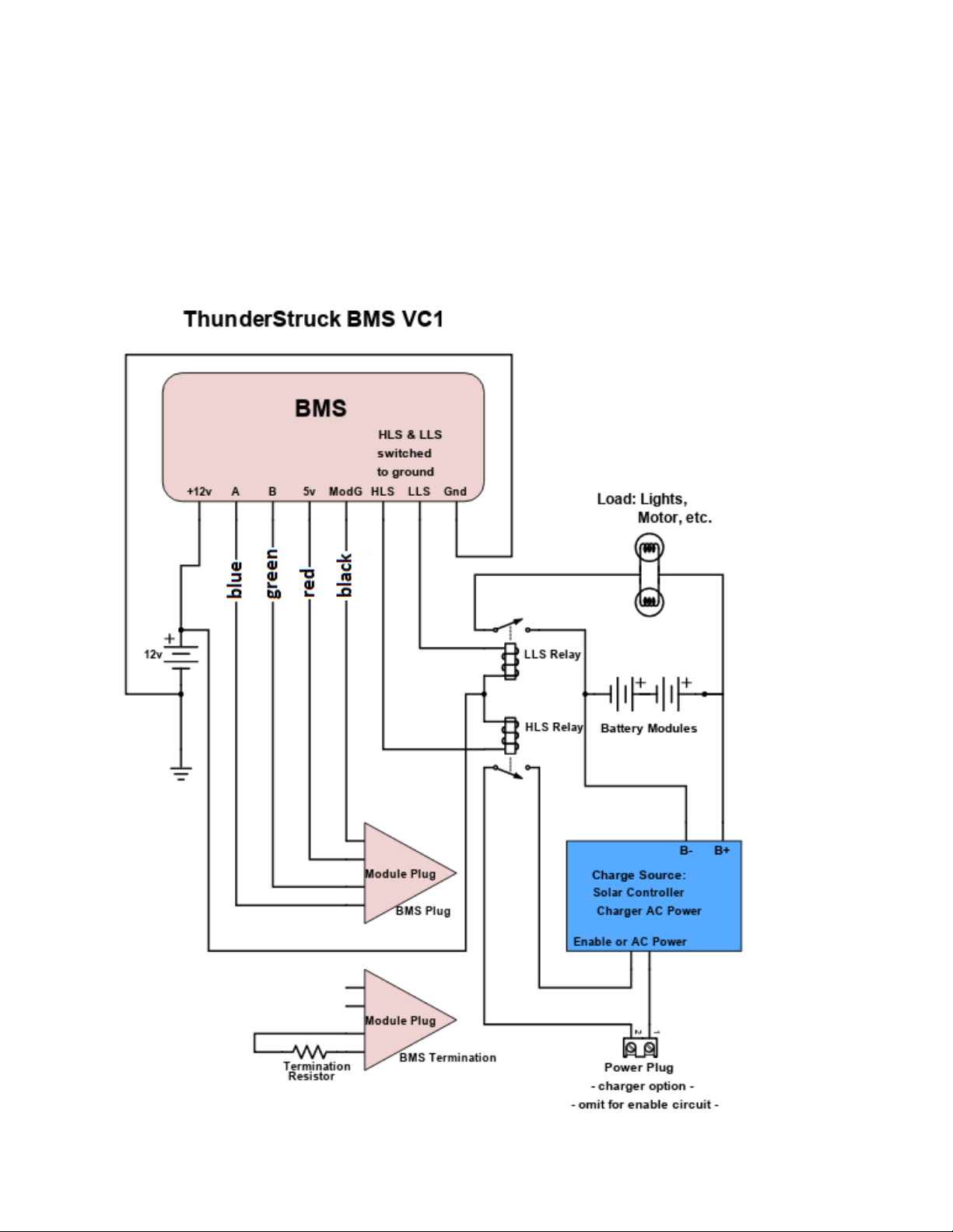
Wiring Instructions
Build up the pack, attach power interconnects and verify power output, then connect module
plugs between modules until all but the end plugs are connected. Connect the BMS
Termination and BMS Plug (see below) to the end module connectors. Next, refer to the
diagram below and complete the BMS wiring per the actual system requirements.
Charge and load enable circuits are controlled by relays. If controlling power circuits, use
relays/contactors rated for charge and load voltage and current. A DCDC converter from the
pack is required if a 12 volt battery or supply is not available

Configuration
After the wiring is complete and you are communicating with the BMS, you can configure the
BMS to work with your group of battery modules. If you purchased your modules along with
the BMS, the configuration should be already completed and locked. If not, then take the
following steps to configure your system.
Start by entering the “update” command to show all the modules connected to the BMS. If all
the modules in your system are not shown in the list, then plug each module individually into
the BMS and “update” again. Label each module using the listed ID. Use the “set mod”
command (see “Commands” below) to change the ID of one module with any duplicate ID. Plug
in all the modules again and enter “update” to verify all are present.
Once the modules are verified, enter the “lock” command to save that set of module IDs. After
this step, the HLS and LLS limit switches will be active.
To change the HVC and LVC values, use the “set” command (below). If changed, also set the
HVCC and LVCC values. Set the HVCC approximately 0.1 volt below the HVC value, and set the
LVCC value 0.1 volt above the LVC value.
High & Low Limit Switches
The BMS has two limit switches that can be used to control other devices. Both the HLS (High
Limit Switch) and the LLS (Low Limit Switch) are open collector outputs found on many
electronic devices. They behave like a normally open switch which is connected to ground when
activated.
The method for controlling a specific external device depends on features supported by that
device. Many devices have a control/enable input that can be activated directly by a limit
switch from the BMS. If no such options are available, you can also use a limit switch to trigger
a large relay or contactor, indirectly disconnecting the other device from its power. In most
cases the HLS would be used to control a charger or charge controller and the LLS would be
used to control whatever you are trying to power, such as a motor controller, AC inverter, LEDs,
buzzer, etc.
Commands
The following commands are available in the VC1 –these are not case sensitive.
•“update” displays a list of connected modules and their ID values
•“show cells”lists the connected set of modules along with module cell voltages
•“show config” shows the list of configuration settings
•“debug” shows a list of errors useful for troubleshooting
•“lock” saves the current pack ID list (required for operation)
•“set” sets parameter values, using “set (parameter) (value)” - Example: “set hvc 3.55”
•“set mod” used to change a module ID. Example: change 3 to 9, enter: “set mod 3 9”
•“enabled” sets LS output logic. Default is closed when enabled. Example: to set HLS
open when enabled: “set HLS enabled open”( “HLS” is case sensitive on early versions)
•“help” lists the command options available to the user

Parameters
•“hvc” (high voltage cutoff) is the high voltage limit at which the BMS will open the HLS
•“lvc”(low voltage cutoff) is the low voltage limit at which the BMS will open the LLS
•“hvcc” (high voltage cutoff clear) is used to buffer cycling of the High limit switch. If a
cell reaches HVC during charge, the BMS will shut off the charger, and the cell voltage
drops slightly. The charger will turn back on below HVC, and the cycle repeats. Setting
the HVCC below the HVC creates a delay to eliminate rapid cycling. The charger turns
back on only after the highest cell voltage drops below HVCC.
•“lvcc” (low voltage cutoff clear) works the same as HVCC, but responds to the low end
of the cell voltage range. This allows for turning the load back on only after the lowest
cell voltage rises above LVCC.
•“tmax” maximum temperature in Centigrade for charge or discharge
•“tmin” minimum temperature in Centigrade for charge or discharge
Terms
•BMS –Battery Management System
•HLS –High Limit Switch
•LLS –Low Limit Switch
•DCDC –DC to DC converter, typically providing 12v power from main pack voltage
•OTG –On The Go (type of USB cable)
•Relay –an electromechanical switch allowing a low power source to control a higher
power source
•Contactor –a relay used to control high current circuits
Default Settings
The following example shows default voltage configuration settings programmed into the BMS
before shipping. These can be changed as needed for specific applications.
hvc: 3.600
hvcc: 3.500
lvc: 3.000
lvcc: 3.100
tmax: 50.00c
tmin: 5.00c
HLS Enabled State: CLOSED
LLS Enabled State: CLOSED
Product Variations
Feature variation may be found in different product versions. Please contact ThunderStruck
Motors with any questions about product features.
707.578.7973
Table of contents


