MSI WindBOX MS-9B05 User manual

i
MS-9B05
WindBOX
Industrial Data Machine

ii
Preface MS-9B05
Copyright and Trademarks Notice
Copyright © Micro-Star Int’l Co., Ltd. All rights reserved. The MSI logo used is
a registered trademark of Micro-Star Int’l Co., Ltd. All other marks and names
mentioned may be trademarks of their respective owners. No warranty as to
accuracy or completeness is expressed or implied. MSI reserves the right to
make changes to this document without prior notice.
Revision History
Revision Date
V1.1 2020/01
Technical Support
If a problem arises with your product and no solution can be obtained from
the user’s manual, please contact your place of purchase or local distributor.
Alternatively, please visit https://www.msi.com/support/ for further guidance.

iii
Preface MS-9B05
Safety Instructions
■Always read the safety instructions carefully.
■Keep this User’s Manual for future reference.
■Keep this equipment away from humidity.
■Lay this equipment on a reliable at surface before setting it up.
■The openings on the enclosure are for air convection hence protects the
equipment from overheating. DO NOT COVER THE OPENINGS.
■Make sure the voltage of the power source and adjust properly 110/220V
before connecting the equipment to the power inlet.
■Place the power cord such a way that people can not step on it. Do not place
anything over the power cord.
■Always Unplug the Power Cord before inserting any add-on card or module.
■All cautions and warnings on the equipment should be noted.
■Never pour any liquid into the opening that could damage or cause electrical
shock.
■If any of the following situations arises, get the equipment checked by ser-
vice personnel:
▶The power cord or plug is damaged.
▶Liquid has penetrated into the equipment.
▶The equipment has been exposed to moisture.
▶The equipment does not work well or you can not get it work according
to User’s Manual.
▶The equipment has dropped and damaged.
▶The equipment has obvious sign of breakage.
■DO NOT LEAVE THIS EQUIPMENT IN AN ENVIRONMENT UNCONDI-
TIONED, STORAGE TEMPERATURE ABOVE 60oC, IT MAY DAMAGE THE
EQUIPMENT.
警告使用者:
此為甲類資訊技術設備,於居住環境中使用時,可能會造成射頻擾動,在此種情
況下,使用者會被要求採取某些適當的對策。
iv
Preface MS-9B05
Chemical Substances Information
In compliance with chemical substances regulations, such as the EU REACH
Regulation (Regulation EC No. 1907/2006 of the European Parliament and the
Council), MSI provides the information of chemical substances in products at:
https://www.msi.com/html/popup/csr/evmtprtt_pcm.html
Battery Information
European Union:
Batteries, battery packs, and accumulators should not be
disposed of as unsorted household waste. Please use the
public collection system to return, recycle, or treat them in
compliance with the local regulations.
廢電池請回收
Taiwan:
For better environmental protection, waste batteries should
be collected separately for recycling or special disposal.
California, USA:
The button cell battery may contain perchlorate material
and requires special handling when recycled or disposed
of in California.
For further information please visit:
https://www.dtsc.ca.gov/hazardouswaste/perchlorate/
Danger of explosion if battery is incorrectly replaced. Replace only with the
same or equivalent type recommended by the manufacturer.
v
Preface MS-9B05
CE Conformity
Hereby, Micro-Star International CO., LTD declares that this device
is in compliance with the essential safety requirements and other
relevant provisions set out in the European Directive.
FCC-A Radio Frequency
Interference Statement
This equipment has been tested and found to comply with
the limits for a Class A digital device, pursuant to Part 15
of the FCC Rules. These limits are designed to provide reasonable protection
against harmful interference when the equipment is operated in a commercial
environment. This equipment generates, uses and can radiate radio frequency
energy and, if not installed and used in accordance with the instruction manual,
may cause harmful interference to radio communications. Operation of this
equipment in a residential area is likely to cause harmful interference, in which
case the user will be required to correct the interference at his own expense.
Notice 1
The changes or modications not expressly approved by the party responsible for
compliance could void the user’s authority to operate the equipment.
Notice 2
Shielded interface cables and AC power cord, if any, must be used in order to
comply with the emission limits.
This device complies with Part 15 of the FCC Rules. Operation is subject to the
following two conditions:
1) this device may not cause harmful interference, and
2) this device must accept any interference received, including interference that
may cause undesired operation.
WEEE Statement
Under the European Union (“EU”) Directive on Waste Electrical and
Electronic Equipment, Directive 2012/19/EU, products of “electrical
and electronic equipment” cannot be discarded as municipal waste
anymore and manufacturers of covered electronic equipment will be
obligated to take back such products at the end of their useful life.

vi
Preface MS-9B05
CONTENTS
Copyright and Trademarks Notice................................................................. ii
Revision History ............................................................................................ ii
Technical Support.......................................................................................... ii
Safety Instructions.........................................................................................iii
Chemical Substances Information ............................................................... iv
Battery Information....................................................................................... iv
CE Conformity............................................................................................... v
FCC-A Radio Frequency Interference Statement ......................................... v
WEEE Statement .......................................................................................... v
1 Overview.......................................................................................1-1
System Overview .......................................................................................1-2
System Specications................................................................................1-6
Motherboard Jumpers................................................................................1-9
2 Getting Started.............................................................................2-1
System Internal View .................................................................................2-2
Memory ......................................................................................................2-3
M.2 Slot......................................................................................................2-4
Mini-PCIe Slot ............................................................................................2-5
2.5” HDD/SSD............................................................................................2-6
Wall Mount (Optional) ................................................................................2-8
DIN Rail Mount 1 (Optional).......................................................................2-9
DIN Rail Mount 2 (Optional).....................................................................2-10
VESA Mount............................................................................................. 2-11
3 BIOS Setup...................................................................................3-1
Entering Setup ...........................................................................................3-2
The Menu Bar ............................................................................................3-4
Main ...........................................................................................................3-5
Advanced ...................................................................................................3-6
Boot..........................................................................................................3-12
Security ....................................................................................................3-13
Chipset.....................................................................................................3-22
Power .......................................................................................................3-23
Save & Exit...............................................................................................3-25
Appendix GPIO WDT Programming............................................... A-1
Abstract..................................................................................................... A-2
General Purposed IO ................................................................................ A-3
Watchdog Timer ........................................................................................ A-4

1-1-1
Thank you for choosing the MS-9B05, an excellent industrial data ma-
chine from MSI.
The MS-9B05’s wide heatsink fanless solution eliminates the noise and
the risk of fan failure. Furthermore, it supports VESA wall-mount inter-
face for various scenarios like digital signage, kiosk, industrial control
and POS with aordable expenditure, which not only meets the demand
of Industrial applications but also fullls the needs of companies, govern-
ments and institutes for general applications.
1Overview
1-2
Overview MS-9B05
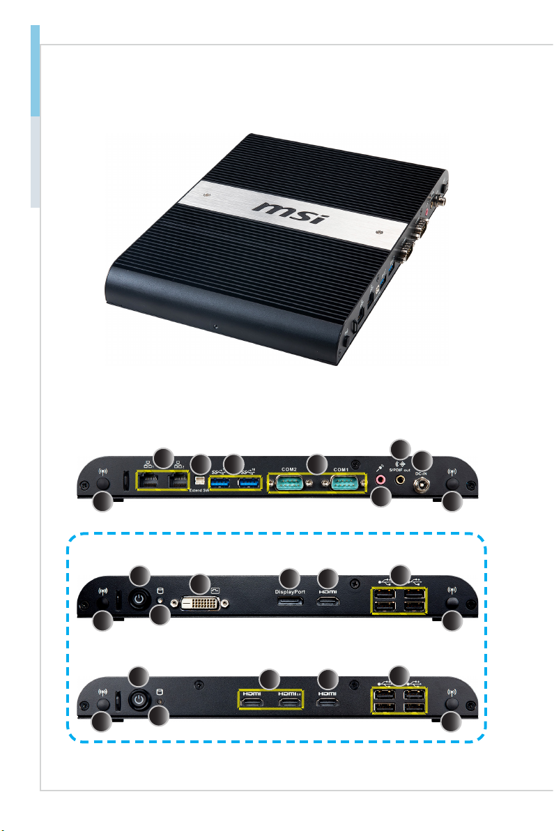
System Overview
hSystem I/O & Controls
SKU1
SKU2
3
6
7
8
16
24 5
1
10
912
11 13 14
1 16
10
1 16
913 14
15
1-3
Overview MS-9B05
1WiFi Antenna Connector (Optional)
This connector allows you to connect an external antenna for wireless
LAN.
2GbE RJ45 Port
The standard RJ45 LAN jack is provided for connection to the Local
Area Network (LAN). You can connect a network cable to it.
3Extend Switch Connector
This connector is provided for remote power button control.
4USB 3.2 Gen 1 Port (For SKU1)
USB 3.2 Gen 1, the SuperSpeed USB, delivers up to 5Gbps high-
speed data transfer for various devices, such as storage devices,
hard drives, video cameras, etc.
USB 3.2 Gen 2 Port (For SKU2)
USB 3.2 Gen 2, the SuperSpeed USB 10Gbps, delivers high-speed
data transfer for various devices, such as storage devices, hard
drives, video cameras, etc.
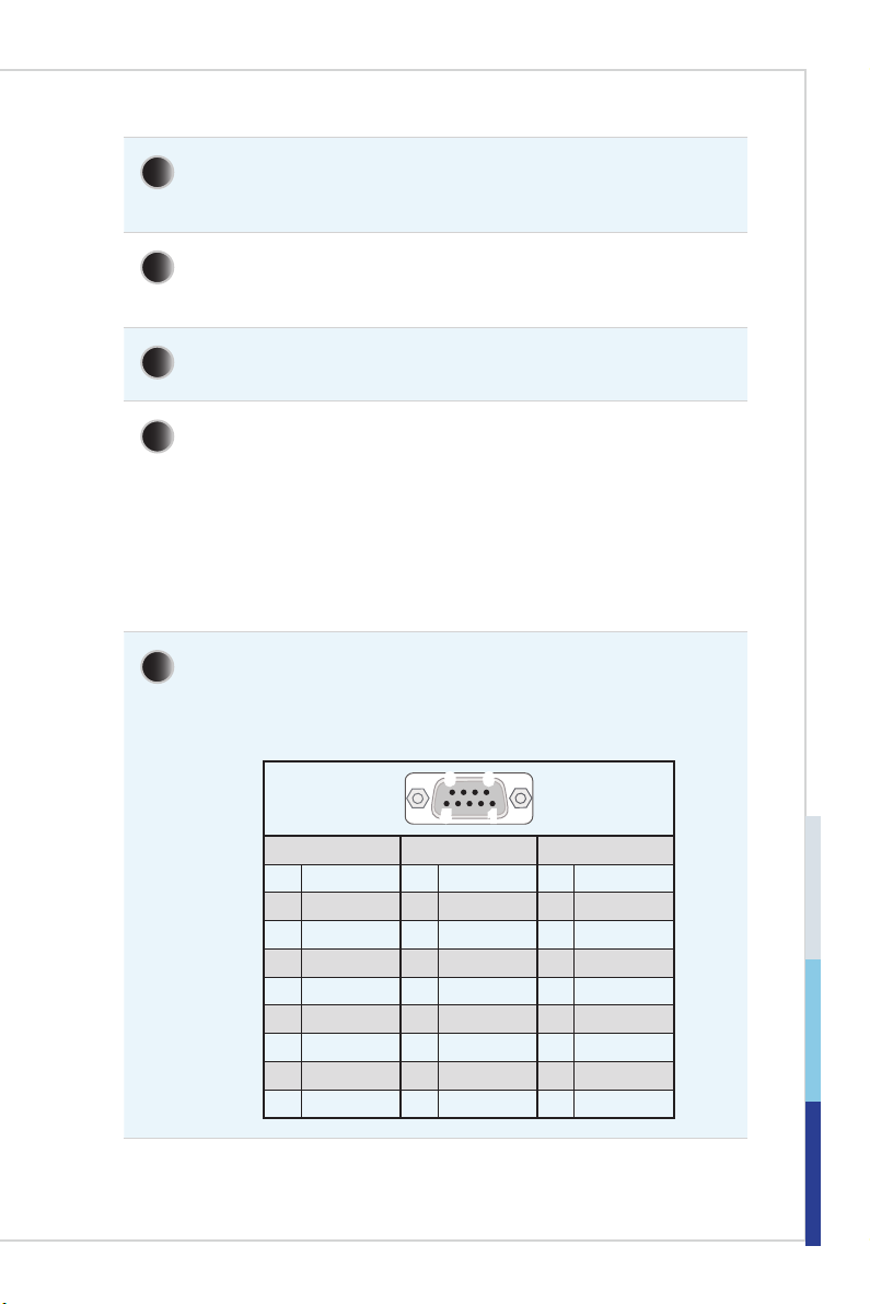
5RS232/422/485 Serial Port
The serial port is a 16550A high speed communications port that
sends/receives 16 bytes FIFOs. It supports barcode scanners, bar-
code printers, bill printers, credit card machine, etc.
51
96
RS232 RS422 RS485
1 DCD 1 TXD- 1 TXD-
2 RXD 2 RXD+ 2 NC
3 TXD 3 TXD+ 3 TXD+
4 DTR 4 RXD- 4 NC
5 GND 5 GND 5 GND
6 DSR 6 NC 6 NC
7RTS 7NC 7NC
8 CTS 8 NC 8 NC
9 RI/POWER 9 NC 9 NC
1-4
Overview MS-9B05
6Mic-In Jack
Used as a connector for a microphone.
Line-In Jack (by AP driver)
Used for connecting external audio output devices.
7S/PDIF-Out Jack
S/PDIF (Sony/Philips Digital Interface Format) is a type of digital au-
dio interconnect used in consumer audio equipment, home theaters
and other digital high-delity systems.
Line-Out Jack
This connector is provided for headphones or speakers.
8DC Power Jack
Power supplied through this jack supplies power to the system.
9Power Button
Press the button to turn the system on or o.
10 Hard Disk Drive LED
This indicator shows the activity status of the HDD. It ashes when
the system is accessing data on the HDD and remains o when no
disk activity is detected.
11 DVI-D Port (For SKU1)
The DVI-D (Digital Visual Interface-Digital) connector allows you to
connect a monitor. It provides a high-speed digital interconnection
between the computer and its display device.
12 DisplayPort (For SKU1)
DisplayPort is a digital display interface standard. This connector is
used to connect a monitor with DisplayPort inputs.
13 HDMI 1.4 Port
The High-Denition Multimedia Interface (HDMI) is an all-digital audio/
video interface capable of transmitting uncompressed streams. HDMI
supports all TV format, including standard, enhanced, or high-deni-
tion video, plus multi-channel digital audio on a single cable.

1-5
Overview MS-9B05
14 USB 2.0 Port
The USB (Universal Serial Bus) port is for attaching USB devices
such as keyboard, mouse, or other USB-compatible devices. It sup-
ports up to 480Mbit/s (Hi-Speed) data transfer rate.
15 HDMI 2.0 Port (For SKU2)
The High-Denition Multimedia Interface (HDMI) is an all-digital audio/
video interface capable of transmitting uncompressed streams. HDMI
supports all TV format, including standard, enhanced, or high-deni-
tion video, plus multi-channel digital audio on a single cable.
16 LTE Antenna Connector (Optional)
This connector allows you to connect an external antenna for LTE.

1-6
Overview MS-9B05
System Specications
Processor
■SKU1: 8th Gen Intel® Mobile Whiskey Lake-U Celeron® Processor, DC, 15W
■SKU2: 8th Gen Intel® Mobile Whiskey Lake-U Core™ i5 Processor, QC,
15W
Memory
■2 x 260-pin SO-DIMM slots
■Support the maximum of 32GB
■SKU1: Dual-channel for DDR4 2133 MHz
■SKU2: Dual-channel for DDR4 2400 MHz
Network
■1 x Intel®I219LM GbE LAN PHY
■1 x Intel®I210-AT GbE LAN
Storage
■1 x SATA 6 Gb/s, 2.5” HDD/SSD
■1 x mSATA slot (shared with Mini PCIe)
Expansion Slot
■1 x Half/Full-size Mini PCIe slot (w/ mSATA)
■1 x Half/Full-size Mini PCIe slot (w/ Nano-SIM holder)
■SKU1
»1 x M.2 E Key 2230 slot (2 x PCIe x1, USB 2.0)
»1 x M.2 M Key 2242 slot (PCIe x4)
■SKU2
»1 x M.2 E Key 2230 slot (2 x PCIe x1, USB 2.0)
»1 x M.2 M Key 2242 slot (PCIe x4, SATA)
Important
• MS-9B05 only supports installing ONE WiFi / BT module. Please install
yourWiFi/BTmoduletoMiniPCIeslot1,MiniPCIeslot2orM.2EKeyslot.
Audio
■Realtek®ALC887-VD2-CG HDA Codec
■Compliant with Azalia 1.0 specs
1-7
Overview MS-9B05
Graphics
■Intel®UHD Graphics 620
■Shared system memory up to 1.7 GB SDRAM
■3 independent displays
■SKU1
»HDMI 1.4 up to 4096 x 2160 @24Hz
»DisplayPort 1.2 up to to 4096 x 2304 @60Hz
»DVI-D up to 1920 x 1200 @60Hz
■SKU2
»HDMI 2.0 up to 4096 x 2160 @60Hz
»HDMI 1.4 up to 4096 x 2160 @24Hz
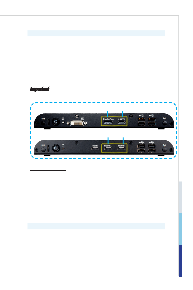
Important
• MS-9B05supportsCollage Display Modewithtwoindependentdisplays.
SKU1 DP 1.2 HDMI 1.4
SKU2 HDMI 2.0 HDMI 1.4
Checkhttps://www.intel.com/content/www/us/en/support/articles/000006547/
graphics-drivers.htmlfordetails.
• SKU2’s HDMI 2.0 port does not support audio and hot plug.Toensure
properoperationoftheHDMI2.0display,followtheinstructions:
1.Connect theHDMI cablefromthedisplaytotheHDMI2.0port onthe
systemleftpanel.Connectthedisplaypowercord.
2.Disconnect the system power cord to ensure a complete system
shutdown.
3.Reconnectthesystempowercordandpoweronthesystem.
4.Poweronthedisplay.Thedisplayshouldbeabletoworkproperly.
Left Panel Input/Output
■2 x WiFi Antenna Connectors (Optional)
■1 x Power Button
■1 x Hard Disk Drive LED
■1 x DVI-D Port (For SKU1)
■1 x DisplayPort (For SKU1)
■1 x HDMI 1.4 Port
■2 x HDMI 2.0 Ports (For SKU2)
■4 x USB 2.0 Ports

1-8
Overview MS-9B05
Right Panel Input/Output
■2 x WiFi Antenna Connectors (Optional)
■2 x GbE RJ45 Ports
■1 x Extend Switch Connector
■2 x USB 3.2 Gen 1 Ports (For SKU1)
■2 x USB 3.2 Gen 2 Ports (For SKU2)
■2 x RS232/422/485 Serial Ports
■1 x Mic-In Jack/ Line-In Jack (Line-In by AP driver)
■1 x S/PDIF-Out Jack/ Line-Out Jack
■1 x DC Power Jack
Power Supply
■DC-in 9~36V with Lockable DC Jack
Dimension & Weight
■260 x 185 x 27mm
■1.77 kg
OS Support
■Windows 10 IoT Enterprise LTSC/SAC 1809 (64-bit, RS5)
■Linux Ubuntu/ Linux Fedora (by request)
Regulatory Compliance
■EMC: FCC, CE, RCM, VCCI, BSMI
■Safety: BSMI, CE
Environment
■Operating Temperature:
»-10 ~ 50oC (SSD)
»-10 ~ 40oC (HDD)
■Storage Temperature: -20 ~ 80oC
■Humidity: 10 ~ 90% RH, non-condensing

1-9
Overview MS-9B05
Motherboard Jumpers
JATX1
JCMOS1 JME_DIS1
Jumper Name Default Setting Description
JCMOS1 11-2: Normal 2-3: Clear CMOS
JATX1 11-2: ATX 2-3: AT
JME_DIS1 11-2: Normal 2-3: ME Disable


1-2-1
This chapter provides you with the information on hardware setup
procedures. While doing the installation, be careful in holding
the components and follow the installation procedures. For some
components, if you install in the wrong orientation, the components will
not work properly.
Use a grounded wrist strap before handling computer components. Static
electricity may damage the components.
Important
Alwaysunplugthepowercordbeforeinstallinganycomponents.
2Getting Started
2-2
Getting Started MS-9B05
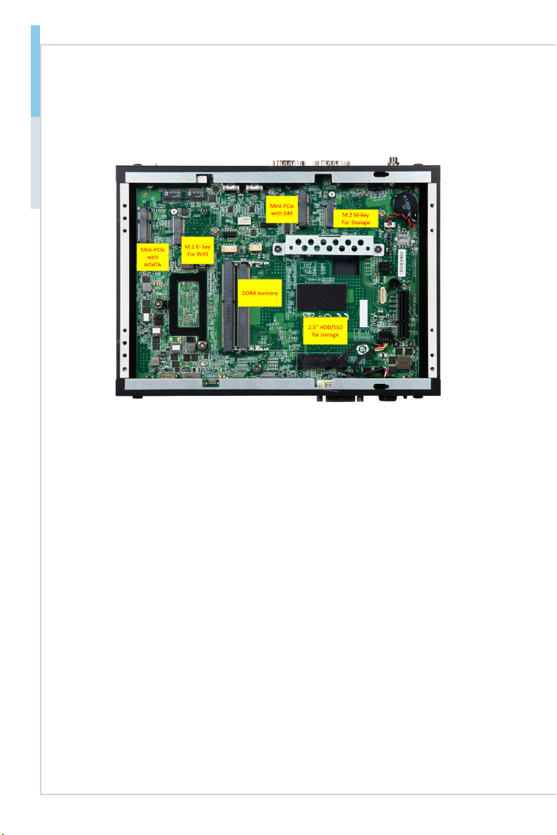
System Internal View

2-3
Getting Started MS-9B05
Memory
1. Locate the SO-DIMM slot.
2. Align the notch on the DIMM with
the key on the slot and insert the
DIMM into the slot at a 45-degree
angle.
3. Push the DIMM gently downwards
until the slot levers click and lock
the DIMM in place.
Important
• Youcanbarelyseethegolden ngerifthe DIMMisproperlyinsertedinthe
DIMMslot.
• To uninstall the DIMM, ip the slot levers outwards and the DIMM will be
releasedinstantly.
2-4
Getting Started MS-9B05
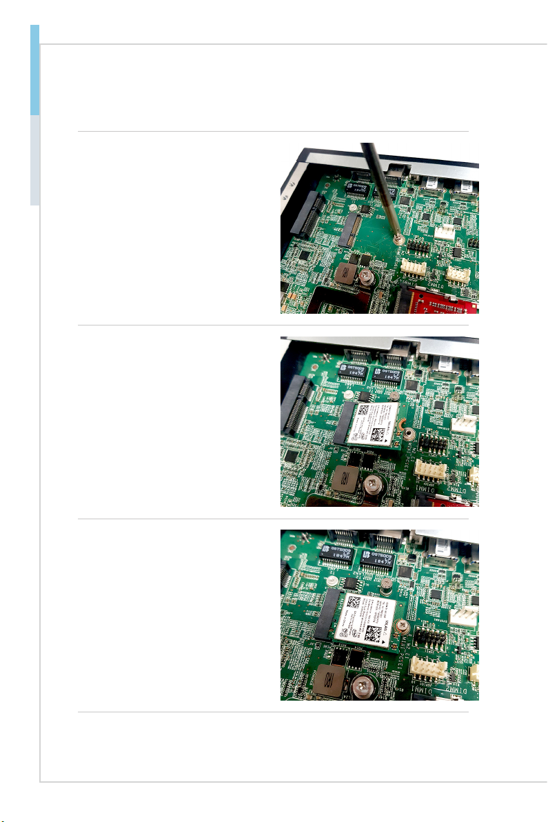
M.2 Slot
1. Locate the M.2 slot. Remove the
M.2 card screw preinstalled on the
motherboard.
2. Insert the card into the slot at a
45-degree angle.
3. Push the card gently downwards
and fasten it with a screw.
Table of contents
Popular Industrial Equipment manuals by other brands


Holmatro
Holmatro GRA4321 manual

Schmalz
Schmalz SGM-HP 40x121 Assembly instructions

SCHUNK
SCHUNK KSC3 Installation and operating instruction

Minebea Intec
Minebea Intec S-Type Load Cell LC Tigo PR 76 installation manual

ABB
ABB Power2 800-M Assembly instructions

Endress+Hauser
Endress+Hauser Cleanfit CPA875 operating instructions