SMG Rapid-Edge 10H User manual

SMG Rapid-Edge 10H Portable
Plate Beveling Machine
Operator’s Manual

Part 1: Intended Use
The weld-edge milling machine is a hand-held, electrically powered device that can be used:
●For machining work pieces made of steel, chromium steel, fine-grained steel, aluminum,
aluminum alloys, brass and plastics
●For commercial use in industrial settings and in the skilled-trades
●For preparing K, V, X and Y-shaped welding grooves
●For creating visible edges in plant and mechanical engineering work.
________________________________________________________________________
Risk of injury or damage to health!
The machine may only be used for work and materials described in the
section “Intended use”.
Do not use the machine to work on materials containing asbestos.
1. Technical Data
Technical Data
Rapid-Edge 10H
Bevel Width
[mm]
1-10
Radius
[mm]
2-4
Bevel Angle
[deg]
30° 37.5°,45°(Choose)
Power
[W]
1800
Milling Spindle Speed
[1/min]
2400-7500
Weight
[kg]
6.5
Line Voltage/Frequency
[V/HZ]
220-240/50
No of cutting tools per head
4

2. Safety Information
Before using the machine, the operating manual and safety instructions must have been read
and understood in their entirety. The instructions contained therein must be strictly followed.
Electrocution hazard!
●Always disconnect the machine from the power supply before
servicing.
●Before each use, always check the plug, cable and machine for
signs of damage.
●The machine must be kept dry. Do not use in damp locations or
humid
●environments.
●If used out of doors, the machine must be protected by a
residual-current circuit-breaker with a maximum tripping
current of 30 mA.
Improper use can cause serious injury!
●Always wear safety goggles, ear protectors, gloves and safety
shoes.
●When working with the machine.
●Insert plug only when the machine is switched off.
●Disconnect the machine from the power supply after use.
Improper use can cause damage to equipment and property!
●Never lift or carry the machine by its power cable.
●Make sure the cable is directed behind and away from the
machine.
●Do not lay cable over sharp edges.
●Testing and servicing must only be carried out by an
appropriately qualified technician.

3.1 Check Cutting Tools
●Blunt tools can cause damage and can overload the machine
●Inspect the cutting tools regularly for signs of wear
●Make sure the cutting edges of the inserts are sharp as this will
improve performance and protect the machine from damage
●Rotate or replace the indexable inserts before they become
blunt.
3.2 Adjusting height of bevel
●Rotate the locking ring
●Lock the locking ring in this position.
●Use a crescent wrench to tighten the guide
plate device (1) Please do not overtighten.
3.3 Working with the weld-edge milling machine
●Make sure you always have a firm footing when working with the
machine.
●Never touch the milling head when the machine is running.
●When using the machine, always guide it away from you.
●Never use the machine above head height.

1. Press the switch (2) to start the machine
2. Adjust the adjusting wheel (1) to ‘4’
Two-handed operation
Always use two hands to hold and control the machine.
To become acquainted with the machine, we recommend that
you begin by machining a small bevel no more than 2mm in
height and advance the machine slowly at first

4. Step-by-step guide to milling with the Rapid-Edge 10H
1. Move the machine into contact with the workpiece only after the selected tool speed
has been reached.
2. Guide the machine along the workpiece only after the spacer guide-bearing has made
contact with the workpiece.
3. When initially cutting the bevel, the machine must always be moved from left to right.
Make sure you know which way the milling head is rotating. The machine should only be
used for conventional (upcut) milling.
4. When machining bore holes, always work in a clockwise direction.
Switching off the Rapid-Edge 10H
1. Remove the milling machine from the workpiece and switch off.
2. The motor will switch off.

5. Step-by-step guide to milling with the Rapid-Edge 10H

6. Changing the Milling Head
General precautions
●Switch off the machine by releasing the on/off switch.
●Pull out the power cable plug from the mains socket.
●Make sure that the machine cannot be switched on again accidentally or by
unauthorized persons.
Removing the Rapid-Edge 10H Milling Heads
●Rotate the guide-plate unit (guide plate + mount) back as far as possible
●Position a spanner on the flats of the drive shaft
●Loosen the central socket-head fitting bolt using the hex key (Allen key) supplied
●Loosen the milling head from the shaft, using the hook spanner provided
●Remove it together with the spacer guide-bearing (comprising fitting bolt, guide bearing
and guide bushing, shims and spacer ring)
●Always store the milling head and the spacer guide-bearing together

7. Fitting New Indexable Cutting Inserts
Procedure
●Switch off the machine by releasing the on/off switch.
●Pull out the power cable plug from the mains socket.
●Press and hold down the safety button on the top of the gearing housing.
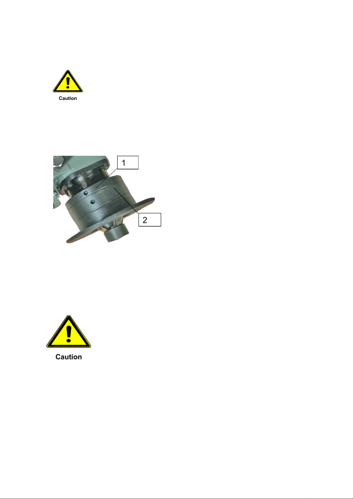
●Loosen the locking screw and remove the cutting insert.
●Clean the area where the insert sits (mounting face and shoulder) and check for damage
●Always rotate or exchange all the inserts on the milling head at the same time
●Make sure that the new inserts are all of identical type
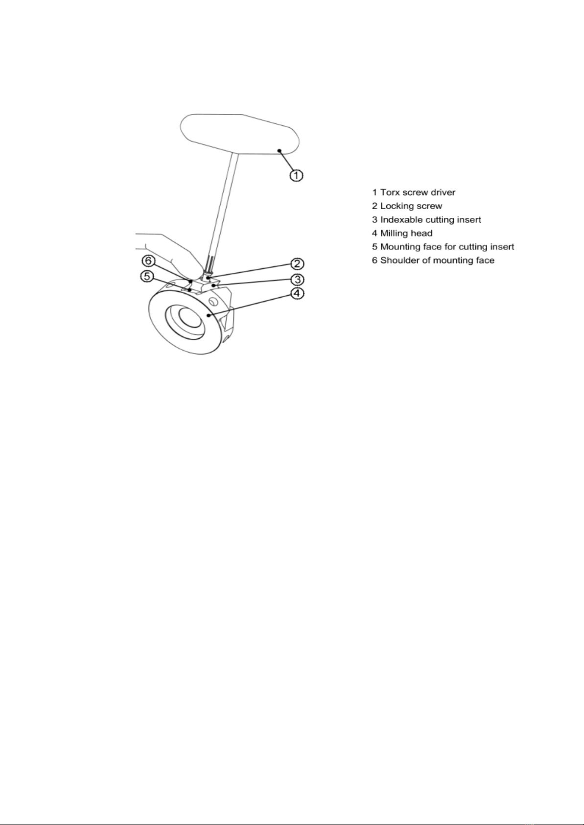
●Press each insert into position so that it lies perfectly flat on the lower part of the
mounting face (5)
●With the insert still properly positioned, tighten the screw with the Torx screwdriver (1)
hand tight so that the insert lies up against the shoulder of the mounting face
●Once all inserts are in position, retighten each of the screws
●Check to make sure that all the indexable inserts on the milling head are of the same
type, that each insert is properly located on the mounting surface and butted up against
the shoulder, and that all screws are tight
●Start with a small bevel and guide the machine slowly onto the material to be milled. If
the machine kicks back, switch off the machine immediately and check again that the
indexable inserts are all of the same type and that they have been fitted exactly as
described above. If the machine kicks back again, you will need to replace the entire set
of inserts.

Failing to change the cutting inserts in time can result in damage to the machine
The mounted inserts have to be close to the guiding bearing, which means small inserts have to
be fixed in the top thread under the guiding bearing. Long and radius inserts has to be fixed in
the middle positioned thread.

8. Speed adjustment
Material
Rapid-Edge 10H
Speed setting
Power-on Time
Aluminum,copper,plastic
Speed 4-6
Approx.5500-7300rpm
100%
Material with a tensile
Strength≤400N/mm2
Speed 3-5
Approx.4500-6500rpm
80%
Material with a tensile
Strength>400N/mm2
Speed 2-3
Approx.2400-5500rpm
60%
Chromium steels, stainless
steels, fine-grained steels
Speed 2-3
Approx.2400-5500rpm
40%
Information on adjusting the machine speed:
1. Start by adjusting a medium speed setting(‘4’).
2. Commence cutting using a small bevel height.
3. If excessive sparks are generated during cutting, reduce the machine speed
4. If no spark showers are evident, machine speed can be increased
5. The higher the tool speed, the faster the machine can be advanced along the workpiece
6. The more sparks produced, the greater the wear on the cutting inserts
7. Specially coated indexable inserts can withstand higher operating temperatures and
can therefore be used at higher machine speeds and can cope with higher levels of
spark generation.
Table of contents
Popular Industrial Equipment manuals by other brands

Envirotainer
Envirotainer Releye RLP 160020R user manual

Bend-Tech
Bend-Tech Dragon mAchines troubleshooting guide

SCHUNK
SCHUNK EOA-UR3510-PSH22-1 Assembly and operating manual

ABB
ABB HT609308 Operation manual

Task Force Tips
Task Force Tips HANDLINE Maintenance manual

Dungs
Dungs GasMultiBloc MB-D B01 Operation and assembly instructions