Tidd Tech G2 User manual

1
PN: 040101-04 - G2 Gooseneck Hitch Assembly, Instructions • Rev 2-13-2020
You will nd the most up to date version of this document on our website
www.tiddtech.com/resource-center/tidd-tech-manuals
1100 Roundhouse Road • Spooner, WI 54801
Toll Free: 1-877-843-3832 • Local: 1-715-635-3220
Website: www.tiddtech.com • Email: [email protected]
IDD
ECH
Snow Grooming Equipment
G2 GOOSENECK HITCH ASSEMBLY
Instruction Manual

2
PN: 040101-04 - G2 Gooseneck Hitch Assembly, Instructions • Rev 2-13-2020
Packing List
G2 Gooseneck Hitch Assembly
L (1) Main Gooseneck Hitch Body (“L” shaped piece)
L (2) Tidd Tech decals; one centered on each side of the horizontal tubing
L (1) Jack Plate (at plate with 4 holes)
L (4) 3/8” x 3-1/4” HB + LN connecting plate to main body
L (1) Channel Stiener
L (2) 1/2” x 3-1/4” HB, FW + LN, connecting stiener to back of hitch plate; bolt heads against
channel; washers and lug nut against SST face
L (1) 1-7/8” Coupler Assembly with locking mechanism in place
L (1) 1/2” x 2-3/4” HB (installed)
L (2) Brace Assemblies (right and left)
L (2) 3/8” x 2” square U-bolts + LN inserted into base plate holes
L (2) 3/8” x 3” HB + LN inserted into one set of top plate holes
L (1) Tube Jack (3000 lb. side wind, bracketless)
L (1) Corrugated box 36x5x24
3
PN: 040101-04 - G2 Gooseneck Hitch Assembly, Instructions • Rev 2-13-2020
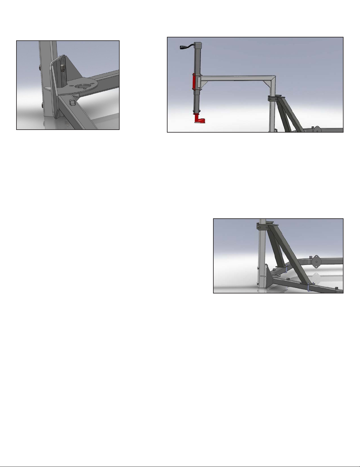
Remove your old hitch from the front of
the G2. Assemble the main “L” shaped
part of the Gooseneck Hitch, channel
backing plate, (2) 1/2” x 3-1/2” hex bolts
and (2) 1/2” lock nuts as shown in the
picture, and tighten securely.
Use the (4) 3/8” x 3-1/4” hex bolts and locknuts to loosely fasten the
Jack Plate to its mate at the top end of the main hitch body. Slide the
tube jack down between the two plates so that the bottom end of the
jack exterior tube is about two inches below the bottom of the plates.
Make sure that the jack is oriented so that the jack handle is forward
towards the snow mobile. Tighten fasteners just enough to hold the
jack temporarily in place. The 1/2” x 2-3/4” hex bolt will allow you to
attach the hitch coupler to the bottom of the jack.
To start, use a piece of wood or some other prop to hold your unhitched G2 up o the ground so that its frame is parallel to
the ground.
Find the (2) 3/8” x 2” U-bolts and locknuts to loosely attach the bottom of
the right and left braces to the G2 front frame. The (2) 3/8” x 3” hex bolts
are used to bolt the top of the braces together and secure them to the main
gooseneck frame. Tighten these top fasteners rst and then the U-bolts.
Back your snowmobile up so that the hitch ball is below the coupler.
Adjust the jack between the mounting plates so that the coupler sits two or
three inches above your ball. Secure all fasteners sandwiching the jack be-
tween the jack plates. Use the jack crank to lower the coupler over the ball
and engage the locking mechanism to hold the coupler in place. If you have
everything properly adjusted, the front frame of the G2 should be parallel to
your trail surface. Remember, these nal adjustments should be done with
someone sitting on the snowmobile to mimic a grooming scenario.
TIPS FOR USING THE G2 GOOSENECK HITCH
1.Use the toothbar and actuator to hitch and unhitch. Run the toothbar all the way down (with a6” wood block under each end)
to take the weight o the hitch. Release the coupler lock andwind the hitch all the way up. Now you can maneuver your snow
machine.
2.When you get stuck, do the same as above – you can raise the toothbar all the way up andstomp loose snow with your boot
under the raised toothbar. Now, if you lower the toothbar itwill raise the machine upwards, taking the weight o the hitch. You
can unhitch and move thesnow machine back to rm trail surface and then back up to within reach (a sharp angle isne). Pivot
the G2 by pulling on the gooseneck hitch to swing it over to where you can re-hitchto the snow machine. Just remember once
you are re-hitched to raise the toothbar before youattempt to pull away!
3.Experiment with how far you can jack-knife your G2 and snow machine with the GN hitch. Wehave found it very easy to turn
completely around on a 10’ wide trail by simply pulling over tothe far side, backing up (while turning) until reaching “maximum
jack-knife” and then pullingforward pointing the opposite direction. This will leave snow machine marks on the trail, but inmany
cases that is not a problem.
More Information
Stay tuned to our website, www.tiddtech.com, for updates and information specic to using the G2, and XC trail grooming in
general. Please let us know when you discover something that you think other trail groomers would appreciate knowing. We
like your feedback!

4
PN: 040101-04 - G2 Gooseneck Hitch Assembly, Instructions • Rev 2-13-2020
IDD
ECH
Snow Grooming Equipment
1100 Roundhouse Road • Spooner, WI 54801
Phone: 1-877-843-3832
Email: [email protected]
www.tiddtech.com
LIMITED WARRANTY FOR TIDD TECH PRODUCTS BY TIDD TECH
Products from Tidd Tech carry a one year warranty. If the equipment fails due to a defect in materials or workmanship within
one year from the date of purchase, Tidd Tech will repair or replace the part free of charge.
This warranty is not transferable and does not cover damage resulting from anything other than defects in material or work-
manship. This warranty does not cover damage caused by unreasonable use, nor replacement of non-defective parts that may
wear and need to be replaced within the warranty period.
For warranty service you must, at your own expense, arrange to deliver or ship the product or part(s) for warranty repairs to
Tidd Tech at the address below.
This limited warranty is in lieu of all other express warranties. Tidd Tech shall not be liable for any special, incidental or con-
sequential damages.
This warranty gives you specic legal rights, and you may also have other rights which vary from state to state.
Table of contents


