IMI BPGS10H Series User manual

BPGS10H
PNEUMATIC
GRIPPER SYSTEM
BPGS10H
User Manual
We make
things MOVE
®

BPGS10H PNEUMATIC GRIPPER SYSTEM
User Manual
BIM-BPGS10H-0719 Rev 1 | For Technical Assistance: 800-442-4622
2
WARNING
Using the equipment in a manner not specified in this manual can impair the safety of the equipment.
Technical support is available from:
Bimba Manufacturing Company
25150 S Governors Hwy University Park, Illinois 60484
Phone: 708-534-8544 Toll Free: 800-44-BIMBA Fax: 708-235-2014
SCOPE OF THIS MANUAL
This instruction manual supports Bimba standard components only. If special components are included
based on a customer’s specifications or special request, it is the customer’s responsibility to consult
support materials and technical support specific to these special components provided by the third party
manufacturers. Bimba assumes no liability for misuse, misapplication, or support for components that are
not the Bimba brand.

BPGS10H PNEUMATIC GRIPPER SYSTEM
User Manual
BIM-BPGS10H-0719 Rev 1 | For Technical Assistance: 800-442-4622
3
Purpose 4
Scope 4
Safety 4
Equipment Required 4
Procedures 4
Gripper Unlock 5
Jaw Removal 5
Jaw Replacement 6
Installing a Side Plate 7
Installing a Indirect Sensor 8
Pad Replacement 9
Calibrating Indirect Sensor 10
Cleaning and Maintenance 11
Quality Assurance Requirements 11
Specifications 11
TABLE OF CONTENTS

BPGS10H PNEUMATIC GRIPPER SYSTEM
User Manual
BIM-BPGS10H-0719 Rev 1 | For Technical Assistance: 800-442-4622
4
PROCEDURES
1. Port size and operation - For Top, Right, Bottom and Left Air Port Orientation
a.) Ports are available in 1/8" NPS or 1/8" Rc
2. For Rear Air Port Orientation:
a.) Ports are available in 1/8" NPS, with hexagon socket head straight fittings supplied with telescope
BPGS10TELXXP
PURPOSE
This document instructs the operator how to use the BPGS10H Grippers
SCOPE
This work instruction covers Port Size and Operation, unlocking of jaws and setting open jaw angles.
SAFETY
Safety glasses or approved eye protection must be worn at all times. Steps involving chemical bonding require the use of
EQUIPMENT REQUIRED
Standard Bench Tools.
Gripper Close
Gripper Open
Gripper Open
Gripper Open
proper ventilation and skin protection in accordance with manufacturer's MSDS.

BPGS10H PNEUMATIC GRIPPER SYSTEM
User Manual
BIM-BPGS10H-0719 Rev 1 | For Technical Assistance: 800-442-4622
5
GRIPPER UNLOCK
1. Release jaw by using a hex key or flat screwdriver and push on drive pin through slot in side plate.
JAW REMOVAL
1. Unlock gripper as shown above and remove pad(s) from existing jaws. Set a side for reassembly.
2. Top jaw should always be removed first. Remove SHCS and Schnorr washer from side plate. Rotate side plate up
to about 45° and remove side plate from gripper. Set SHCS and side plate aside for re-assembly.
4. Remove SHCS and Schnorr washer from side plate. Rotate side plate up to about a 45° angle and remove
from gripper. Set SHCS and side plate aside for re-assembly.
3. Remove jaw from gripper and flip gripper over to remove other jaw.

BPGS10H PNEUMATIC GRIPPER SYSTEM
User Manual
BIM-BPGS10H-0719 Rev 1 | For Technical Assistance: 800-442-4622
6
JAW REPLACEMENT
1. For lower jaws (10151, 11102 and 11103): Apply high-temperature grease to cam and inside of jaw. Angle new
jaw so that tail of jaw goes in the pocket of frame. Align pivot hole with boss and drive pin with the bottom side
of the cam slot. Carefully slide jaw over boss and onto gripper. Replace bushing over pin and into cam. Apply
high temperature grease to outside of jaw.
2. Refer to "Installing a Side Plate" section.
3. Flip gripper over for top jaw installation.
5. For lower jaws (11103 and 10151): Remove bushing from lower jaw using a small flat screwdriver or hex key
and set aside for re-assembly. Lower jaw should be rotated completely down before removal. Lift up on front
of jaw by pad so there is an angle between the jaw and frame. Remove lower jaw from gripper.
6. For lower jaws (11102): Remove lower jaw from gripper.

BPGS10H PNEUMATIC GRIPPER SYSTEM
User Manual
BIM-BPGS10H-0719 Rev 1 | For Technical Assistance: 800-442-4622
7
4. For upper jaws (10150 and 11102): Apply high-temperature grease to cam and inside of jaw. Replace bushing
over drive pin and onto gripper. Align hole in jaw with boss on frame and cam with bushing. Slide jaw over boss
and drive pin so that the jaw rests on the gripper. Apply high temperature grease to outside of jaw.
5. Refer to "Installing a Side Plate" section.
INSTALLING A SIDE PLATE
1. With the Side Plate at 45°, align pins of side plate with slots of frame. Slide pins into slot. When pins are fully
seated, rotate side plate and slide down onto frame.
2. Add Schnorr washer to M5 X 12mm SHCS. Insert through side plate and into frame. Tighten M5 SHCS to
72in-lb.

BPGS10H PNEUMATIC GRIPPER SYSTEM
User Manual
BIM-BPGS10H-0719 Rev 1 | For Technical Assistance: 800-442-4622
8
INSTALLING AN INDIRECT SENSOR
1. To install an Indirect Sensor, apply a liberal amount of high temperature grease to brass bushing prongs inside
sensor. Next, move the brass bushing in the sensor to align with the drive rod slot in the gripper. This must be
done to correctly install sensor. Make sure the sensor is in the orientation where the cable is pointing to the rear of
the gripper.
2. Apply Loctite 262 or equivalent to the three blind M4 tapped holes.
3. Rotate sensor down onto frame. As rotation begins make sure bushing and drive rod slot are still aligned.
Note: Whenever any part of the gripper is replaced including pads, the sensor will need to be recalibrated. See
"Calibrating Indirect Sensor" section.
Bushing Prongs
Drive rod slot

BPGS10H PNEUMATIC GRIPPER SYSTEM
User Manual
BIM-BPGS10H-0719 Rev 1 | For Technical Assistance: 800-442-4622
9
4. To secure sensor to gripper, flip over while holding sensor to ensure that bushing and drive rod are still aligned.
Clean all three M4 X 30mm SHCS for sensor and insert through gripper body and into sensor. Tighten M4
SHCS to 50in-lb.
PAD REPLACEMENT
1. Unlock jaws on gripper & open jaws to get access to the pads. Side plates DO NOT need to be removed. Refer
to "Gripper Unlock" section.
2. Remove M5X10 mm SHCS along with the 5 mm schnorr washer from jaw.
3. Apply Loctite Silver Grade Anti-Seize to M5 X 10mm SHCS. Make sure 5mm schnorr washer is used along with
M5 X 10mm SHCS before inserting into one of the jaws. Take replacement pad and insert it into the opposite side
of the jaw with the SHCS sticking out. Thread SHCS into pad and tighten to 72in-lb. Repeat step for other jaw.

BPGS10H PNEUMATIC GRIPPER SYSTEM
User Manual
BIM-BPGS10H-0719 Rev 1 | For Technical Assistance: 800-442-4622
10
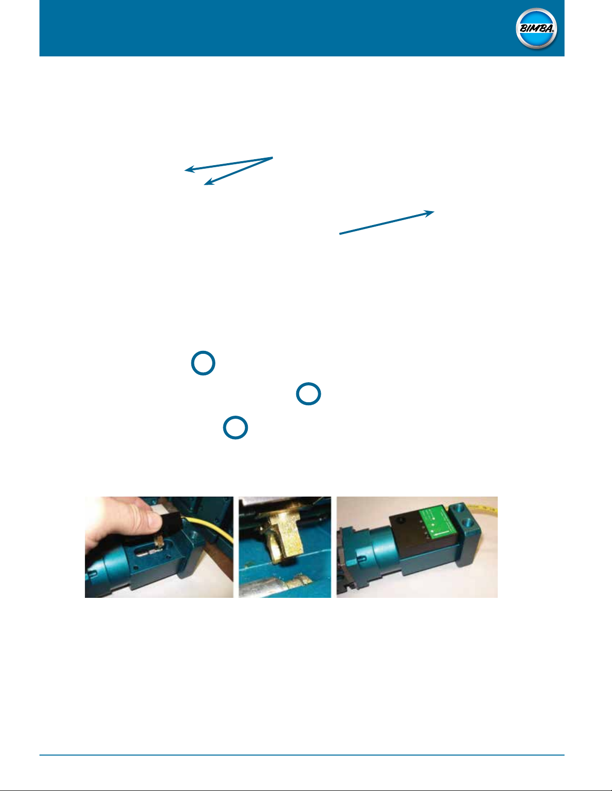
CALIBRATING INDIRECT SENSOR
Sensor must be calibrated whenever any part of the gripper is replaced including pads.
1. Part Present
a) To program the sensor for a particular material thickness, apply air to the gripper and grip on the material
thickness which is to be used for the particular job. With an object such as a small Allen wrench, press the
button until the Red LED corresponding to the material range of the job lights as shown on the label.
b.) Verify calibration:
(1) Close the gripper with no material between the pads. The LED should be o.
(2) Close the gripper on a single blank of material. The Red LED corresponding to your material range
should be on.
2. Double Blank
a) To program the sensor for a particular material thickness, apply air to the gripper and grip on the material
thickness which is to be used for the particular job. With an object such as a small Allen wrench, press the
button until the Red LED(s) corresponding to the material range of the job lights as shown on the label.
b.) Verify calibration:
(1) Close the gripper with no material between the pads. The LED(s) should be o.
(2) Close the gripper on a single blank of material. The Red LED(s) corresponding to the material range
should be on.
0.5 – 0.9mm
1.0 – 1.9mm
2.0 mm - Up
Part Present– Grip 1 Sheet
Press Button for Material range
0.50 – 0.74 mm
0.75 – 0.99 mm
1.00 – 1.49 mm
Double Blank – Grip 1 Sheet
Press Button for Material range
1.50 – 1.99 mm
2.00 – 3.49 mm
3.50 mm - Up
0.5 – 0.9mm
1.0 – 1.9mm
2.0 mm - Up
Part Present– Grip 1 Sheet
Press Button for Material range
0.50 – 0.74 mm
0.75 – 0.99 mm
1.00 – 1.49 mm
Double Blank – Grip 1 Sheet
Press Button for Material range
1.50 – 1.99 mm
2.00 – 3.49 mm
3.50 mm - Up

BPGS10H PNEUMATIC GRIPPER SYSTEM
User Manual
BIM-BPGS10H-0719 Rev 1 | For Technical Assistance: 800-442-4622
11
CLEANING AND MAINTENANCE
a) Remove excess grease from outer surfaces of gripper.
b) No required maintenance.
QUALITY ASSURANCE REQUIREMENTS
a) Verify that jaws shall open freely. Look for any irregular movement, binding, or interference.
SPECIFICATIONS
Gripper Throat Depth
Inch (mm)
Flange Height
Inch (mm)
Working Pressure Double Sided Grip
Force Up To
Actuation Time
BPGS10HF 0.91
(23.1 mm)
60psi (413kPa) Min. –
100psi (689 kPa) Max.
60psi (413kPa) Min. –
100psi (689 kPa) Max.
450lbs (200kgf) @
80psi (551kPa)
0.050±0.010 sec. close /
0.080±0.010 sec. open
BPGS10HR 0.75
(19mm)
60psi (413kPa) Min. –
100psi (689 kPa) Max
60psi (413kPa) Min. –
100psi (689 kPa) Max.
450lbs (200kgf) @
80psi (551kPa)
0.050±0.010 sec. close /
0.080±0.010 sec. open
Regular/Flange Jaw
Single Blank Thickness Moveable Jaw Pad Color Opposing Jaw Pad Color
0.50 mm to 2.0 mm Black Black
2.01 mm to 3.5 mm Silver Silver
3.51 mm to 5.0 mm Gold Silver

BPGS10H PNEUMATIC GRIPPER SYSTEM
User Manual
BIM-BPGS10H-0719 Rev 1 | For Technical Assistance: 800-442-4622
12
TECHNICAL DOCUMENTS
Visit the Bimba website for additional models, drawings, and further documentation.
www.bimba.com
SUPPLIER CONTACT
To purchase gripper products, accessories, or receive further information,
contact your local Bimba distributor or contact Bimba directly.
Bimba Manufacturing Headquarters
25150 S Governors Hwy University Park, Illinois 60484
Phone: 708-534-8544
Toll Free: 800-44-BIMBA
Fax: 708-235-2014
www.bimba.com
© Copyright 2019 Bimba Manufacturing Company. All Rights Reserved. HM-BIM-BPGS10H-0719 Eective July 2019.
This manual suits for next models
2
Table of contents
Other IMI Industrial Equipment manuals
Popular Industrial Equipment manuals by other brands

Woodland Mills
Woodland Mills HM126 Operator's manual

Zaber Technologies Inc.
Zaber Technologies Inc. VSR-E Series user manual

Siemens
Siemens SINUMERIK 808D ADVANCED T user manual

AGCO
AGCO SP002V9810010 Operator's manual

Metso Outotec
Metso Outotec Lokotrack ST4.8 DRIVING INSTRUCTION

Kässbohrer
Kässbohrer SWAP BODY Series user manual