Erin Fingerscreener 206T Operating instructions

© Erin Systems Ltd., 2006
O
Op
pe
er
ra
at
ti
in
ng
g
a
an
nd
d
M
Ma
ai
in
nt
te
en
na
an
nc
ce
e
M
Ma
an
nu
ua
al
l
ISSUE: 2006-05 ERIN SYSTEMS, 2006 (International, #3010)

W
WA
AR
RN
NI
IN
NG
G!
!
P
PH
HY
YS
SI
IC
CA
AL
L
I
IN
NJ
JU
UR
RI
IE
ES
S
A
AN
ND
D
M
MA
AT
TE
ER
RI
IA
AL
L
D
DA
AM
MA
AG
GE
E
C
CO
OU
UL
LD
D
O
OC
CC
CU
UR
R
I
IF
F
T
TH
HE
E
F
FO
OL
LL
LO
OW
WI
IN
NG
G
R
RU
UL
LE
ES
S
A
AR
RE
E
N
NO
OT
T
A
AD
DH
HE
ER
RE
ED
D
T
TO
O
1. Do not operate this equipment without reading and understanding this
manual first.
2. Make sure that the Main Power Supply is OFF before any maintenance
or cleaning operations are carried out.
3. Never use this equipment for functions other than those for which it was
designed.
The information in this document was the most up-to-date available at the time of printing. Because of Erin
Systems policy of ongoing improvement, the company reserves the right to discontinue or update manuals and
technical information as it sees fit, without notice and without further obligation on its part.

Rev: 0-3 (international, serial no. 3010) - iii - May 2006
TABLE OF CONTENTS
1SAFETY 1-1
1.1 General...................................................................................................................................... 1-1
1.1.1 Individual Safety Equipment ........................................................................................ 1-1
1.1.2 Labelling of Controls and Warning Notices.................................................................. 1-2
1.1.3 Cleanliness and Good Order ....................................................................................... 1-2
1.1.4 Hand Tools and Power Tools....................................................................................... 1-2
1.2 Operator Training...................................................................................................................... 1-2
1.3 Operation Safety....................................................................................................................... 1-3
1.3.1 Risk of Contact with Moving Parts............................................................................... 1-3
1.3.2 Protective Guards ........................................................................................................ 1-3
1.3.3 Visual Inspection of Equipment.................................................................................... 1-4
1.3.4 Risk of Shifting or Falling Load .................................................................................... 1-4
1.3.5 Risks related to Machine Mobility ................................................................................ 1-4
1.3.6 Transport Safety of Mobile Equipment......................................................................... 1-6
1.3.7 Risk related to the Use of Ladders............................................................................... 1-6
1.3.8 Lockout Procedure....................................................................................................... 1-7
1.3.9 Electrical Components................................................................................................. 1-8
1.3.10 Fire Prevention............................................................................................................. 1-8
1.4 Glossary of Pictograms............................................................................................................. 1-9
2DESCRIPTION 2-1
2.1 Processing Materials................................................................................................................. 2-1
2.2 Equipment Description.............................................................................................................. 2-2
2.2.1 Description of the Screen Box ..................................................................................... 2-2
2.2.2 Description of Stockpile Conveyors ............................................................................. 2-2
2.2.3 Description of the Main Frame..................................................................................... 2-3
2.3 Technical File............................................................................................................................ 2-3
3OPERATION 3-1
3.1 Safety Recommendations.........................................................................................................3-1
3.2 Description of Controls.............................................................................................................. 3-2
3.3 Operation Procedure................................................................................................................. 3-6
3.3.1 Parking the Machine .................................................................................................... 3-6
3.3.2 Check List Prior to Start Up ......................................................................................... 3-7
3.3.3 Preparing the Machine to Screen ................................................................................ 3-8
3.3.4 Panel View.................................................................................................................3-11
3.3.5 Operating Instructions................................................................................................ 3-12
3.3.6 Moving the Machine................................................................................................... 3-13
3.3.7 Radio Remote Functions ........................................................................................... 3-16
3.3.8 Wire Remote Functions (option)................................................................................ 3-17
3.3.9 Preparing for Transport.............................................................................................. 3-18
4ADJUSTMENTS 4-1
4.1 Screen Box................................................................................................................................ 4-1
4.1.1 Fingers Adjustments .................................................................................................... 4-1
4.1.2 Drive Belt......................................................................................................................4-5
4.2 Tracks Adjustment .................................................................................................................... 4-5
4.3 Acoustic Warning Signals Verification ...................................................................................... 4-6

Rev: 0-3 (international, serial no. 3010) - iv - May 2006
4.4 Remote Control Battery Change............................................................................................... 4-6
4.5 Conveyors................................................................................................................................. 4-7
4.6 Balancing the Screen Box.......................................................................................................4-10
5MAINTENANCE 5-1
5.1 Screen Box Bearings ................................................................................................................ 5-2
5.2 Hydraulic System...................................................................................................................... 5-3
5.2.1 Hydraulic Pumps .............................................................................................................. 5-4
5.3 Maintenance upon Delivery of a New Machine......................................................................... 5-4
5.4 Maintenance Table.................................................................................................................... 5-5
5.5 Erin Bolts and Nuts ................................................................................................................... 5-8
5.5.1 Bolts and Nuts Tables (Imperial System)......................................................................... 5-8
5.5.2 Bolts and Nuts Tables (SI Units)...................................................................................... 5-9
5.6 Maintenance prior to Transport............................................................................................... 5-11
5.7 Maintenance Summary........................................................................................................... 5-12
6TROUBLESHOOTING 6-1
6.1 Controller Warnings .................................................................................................................. 6-1
6.2 Troubleshooting Table .............................................................................................................. 6-2
7PARTS LIST 7-1
7.1 Return of Parts.......................................................................................................................... 7-1
7.2 Parts Ordering........................................................................................................................... 7-1
7.3 Warranty.................................................................................................................................... 7-1
7.4 Suggested Parts List................................................................................................................. 7-2
7.5 Mechanical Parts....................................................................................................................... 7-5
7.6 Electrical Parts .......................................................................................................................... 7-6
7.7 Hydraulic Parts.......................................................................................................................... 7-7
7.8 Manufacturers’ Specifications...................................................................................................7-8

Rev: 0-3 (international, serial no. 3010) - v - May 2006
TABLE OF ILLUSTRATIONS
Figure 2-1 FS-206T General view..............................................................................................................2-2
Figure 2-2 Fingerscreener FS-206T...........................................................................................................2-4
Figure 3-1 Emergency-stop button (near Screen Box raising system)......................................................3-2
Figure 3-2 Emergency-stop button (near Screen Box raising system)......................................................3-2
Figure 3-3 Emergency-stop button (in Power Pack)..................................................................................3-3
Figure 3-4 Emergency-stop button (in Power Pack)..................................................................................3-3
Figure 3-5 Reject and Middle Stackers levers............................................................................................3-4
Figure 3-6 Controls.....................................................................................................................................3-4
Figure 3-7 Fine Stacker and Screen box levers.........................................................................................3-5
Figure 3-8 Control panel.............................................................................................................................3-5
Figure 3-9 Controls location .......................................................................................................................3-6
Figure 3-10 Hopper side extensions ..........................................................................................................3-9
Figure 3-11 Screen Box raising system ...................................................................................................3-10
Figure 3-12 Two or three-product switching system (3-product model only)...........................................3-10
Figure 3-13 Reject Stacker raising system (3-product model only) .........................................................3-11
Figure 3-14 Panel view: Screening mode ................................................................................................3-11
Figure 3-15 Panel view: Traction mode....................................................................................................3-11
Figure 3-16 Radio remote control.............................................................................................................3-16
Figure 3-17 Wire remote control...............................................................................................................3-17
Figure 3-18 Fine Stacker retaining belt....................................................................................................3-18
Figure 3-19 Middle Stacker retaining belt.................................................................................................3-19
Figure 3-20 FS206T Transport Position...................................................................................................3-20
Figure 4-1 Fingers at lowest angle.............................................................................................................4-2
Figure 4-2 Fingers at highest angle............................................................................................................4-2
Figure 4-3 Adjustment bolts........................................................................................................................4-3
Figure 4-4 Grizzly™finger installation........................................................................................................4-3
Figure 4-5 Rod block installation................................................................................................................4-4
Figure 4-6 Cascade™finger removal.........................................................................................................4-5
Figure 4-7 Cascade™finger installation.....................................................................................................4-5
Figure 4-8 Radio remote control battery.....................................................................................................4-6
Figure 4-9 Battery Charger.........................................................................................................................4-7
Figure 4-10 Reject Stacker side panels .....................................................................................................4-9
Figure 5-1 Screen Box bearing grease fitting.............................................................................................5-2
Figure 5-2 Hydraulic oil level indicator .......................................................................................................5-3
Figure 5-3 Machine tie-down points.........................................................................................................5-11
Figure 6-1 Controller warning example......................................................................................................6-1

Safety
Rev: 0-3 (international, serial no. 3010) - 1-1 - May 2006
1 SAFETY
Each equipment user is responsible for understanding and complying with the applicable local,
state and federal laws and regulations on safety and other matters. Erin Systems is not
responsible for any misuse, or accident related to a misuse of this machine or any part of this
machine. Any liability is subject to Erin Systems standard warranty (Erin Systems includes all
related companies, parties, associates and agents involved in design, manufacturing, sales and
administration).
To assist operators in the safe operation of the equipment, Erin Systems recommends the
following minimum safety rules. These rules may require upgrading in order to comply with
local regulations or to accommodate specific operating conditions.
The following general recommendations are intended to cover all equipment sold by Erin
Systems. Please select the ones that apply to the purchased equipment.
1.1 General
CAUTION!
Do not operate Erin equipment under the
influence of drug, alcohol or medication.
Though equipment is fitted with guards to protect operators from moving parts, such shielding
is not always possible and does not always provide complete protection. The operator must
take the necessary precautions in order to avoid injuries.
♦Loose clothes (shirt, sweater, tie, scarf, etc.) must be tucked into pants or other
garment.
♦Workers must wear a shirt and long pants.
♦No jewellery, except a medical alert (Medicalert) necklace or bracelet should be
worn.
♦Long hair must be worn in a net or fastened securely in another manner.
1.1.1 Individual Safety Equipment
When working on or around equipment, workers must wear, as a minimum, the following
individual safety items: glasses, helmet and steel-cap boots. Breathing masks must be worn in
areas where concentrations of contaminants or dust exceed tolerable level. Earplugs must be
worn in an environment where the noise level exceeds the allowable maximum. Long-sleeve

Safety
Rev: 0-3 (international, serial no. 3010) - 1-2 - May 2006
overalls, helmet, visor, gloves and steel-cap boots must be worn at all times when working
close to a hydraulic unit.
1.1.2 Labelling of Controls and Warning Notices
Emergency-stop devices and other equipment controls are labelled with permanent fixed
stickers, as are certain warning notices and instructions for safe and effective operations.
These stickers must remain in place and legible at all times.
Every worker who operates equipment must know the location and operation of all controls
and must understand the warnings and instructions.
1.1.3 Cleanliness and Good Order
A clean and unobstructed workplace reduces the risk of accident. Always make sure that all
moving parts such as conveyors and screens remain free of any debris. Access to exit doors
and electrical control panels must remain unobstructed at all times. Each operator is
responsible for keeping the workstation clean and in good order.
Water, oil or another liquid can make a floor slippery and cause falls or serious injury. Use
appropriate absorbent to sponge up oil spills and then dispose of the absorbent in a controlled
way. Check local, state and federal laws for the disposal of oil.
1.1.4 Hand Tools and Power Tools
Do not use a pipe to extend a wrench handle. Try penetrating oil.
1.2 Operator Training
The safe and effective use of equipment requires the operator chosen for this specific job to
undergo proper training.
Operator training should include a detailed review of the Operating and Maintenance Manual.
The operator must have access to this manual at all times. Pay special attention to the location
and functions of all controls, protective guards and safety devices, including the emergency-
stop controls. No training is complete without thorough knowledge of the safety
recommendations included in the Operating and Maintenance Manual.
No one takes charge of equipment operations until it is verified that he or she has been fully
trained for the equipment in question.

Safety
Rev: 0-3 (international, serial no. 3010) - 1-3 - May 2006
1.3 Operation Safety
CAUTION!
Never take a risk that could result in an injury
to yourself or to a co-worker.
The operator must follow the Operating and Maintenance Manual procedures without
exception.
When operating the equipment, the operator will encounter situations that are not covered in
the manual. In such a case or if a procedure seems dangerous, the operator must shut down the
equipment and advise a supervisor immediately. If modifications are necessary, the operator
and the supervisor must ensure that they both understand the consequences of the chosen
procedure and must prevent injury hazards.
The following general rules will help the operator make decisions but are not sufficient in
themselves. One must always stay alert and pay careful attention to avoid all risks.
1.3.1 Risk of Contact with Moving Parts
Never touch moving parts, such as a conveyor or crank, with hands, feet or any other part of
your body for any reason.
Never step on a conveyor or screen while operating the machine. Always stop the machine
completely before maintenance or cleaning work. Never stay on the machine while moving it.
If a tool or piece of material gets caught in moving equipment, let go immediately and shut
down the equipment.
1.3.2 Protective Guards
Never start equipment if a protective guard, interlock or safety device is missing. If the
operator notices such a problem, he must notify his supervisor. The latter will make sure that
the equipment cannot be used until the problem is solved (see Lockout Procedure).
Never remove protective guards, interlocks or other safety devices, or prevent them from
operating, except when absolutely necessary for adjustment or maintenance. Only authorized
personnel may perform such adjustment or maintenance. They shall ensure that all safety
devices are back to functional status immediately after the adjustments or maintenance have
been carried out.

Safety
Rev: 0-3 (international, serial no. 3010) - 1-4 - May 2006
The access to any door equipped of a lock must be limited to authorized and properly trained
personnel only. Keep such doors or panels locked at all time and do not leave the key available
to unauthorized persons.
1.3.3 Visual Inspection of Equipment
The operator must always inspect the equipment before starting it to make sure it is in good
working condition, and correct any breakage, blockage, leak or abnormal condition if any. If it
is not possible to correct the situation, the supervisor must be advised prior to equipment start
up.
Running equipment must be stopped immediately in case of breakage, blockage, leakage or
abnormal condition. The operator must correct the problem if possible, or refer to the
supervisor in charge.
1.3.4 Risk of Shifting or Falling Load
While the machine is running, keep away from loading area. Never pass or stay under any
conveyor unless the machine is stopped. Do not pass or stay under a load held up by hoisting
equipment such as a crane, forklift, loader, hydraulic or compressed-air piston or inclined
ramp. Where this situation cannot be avoided, make sure that the load would remain in
position – is held by blocks, posts, stays or beams for example – in the event of a power
failure.
Do not place yourself under a load supported by wheels unless the wheels are blocked to
prevent movements.
Whenever the centre of gravity of a load could shift relative to the device used to hoist it or
hold it in place, fix the load securely to the lifting device before moving it.
1.3.5 Risks related to Machine Mobility
Never move the machine while people are standing nearby. Always stay at a minimum
distance of 23 m (75 feet) away from the machine when it is moving or about to be moved.
An optional wire remote control can be provided in case the radio remote can no longer be
used for any reason (breakage, radio system out of order, dead battery, etc.). Be extremely
careful when using this spare remote control. Make sure to have additional help when
moving the machine since the operator cannot back up far enough to have a full view of the
machine path. Always keep the cord tight enough to make sure that the machine does not roll
over the cord. Never use the wire remote while loading the machine on the trailer. Use the
radio remote control and stand at a safe distance from the machine.
When using the radio remote control, do not stand farther than 90 m (300 feet) from the
machine in order to remain within the radio signal range and to provide a safe operation.

Safety
Rev: 0-3 (international, serial no. 3010) - 1-5 - May 2006
Note: The radio range may exceed 90 m (300 feet) but it is recommended to
remain within the required 90 m (300 feet) area for a safer operation of the
machine in traction mode.
Avoid positioning the machine on uncertain ground such as the edge of an excavation, near a
cliff, a road shoulder or any place else where soil collapse is likely to occur. Make sure that
the machine path and destination are safe enough and properly level to avoid getting
obstructed or stuck in the mud. The machine ground pressure is 104.6 kPa (14.4 PSI). The
working surface must be hard enough to support such pressure. The surface is too soft if the
machine sinks in deeper than 15 cm (6 inches). Movements will be harder on such ground.
Refer to the sketch at the end of this chapter for the maximum approach and slope angles. It is
possible to operate the machine on steeper ground but there are more risks for workers and
machinery as well. On soft, brittle or slippery surfaces, the slope angle might have to be
smaller. Do not steer the machine while traveling in a slope. Reach level ground before
switching direction. The recommendations shown on the sketch provide safer moves on
regular ground conditions.
Before turning the remote key, make sure that the stop button is pulled. A 5-second buzzer
starts as soon as the remote is activated. Watch the machine from an angle providing a clear
view of the machine path and all the obstacles that might arise. Do not make the machine run
over obstructions. Always keep the machine into sight during the whole operation. Do not
stand directly in front of the moving machine or on its path. A beeper is activated when the
machine is moving. Make sure that both acoustic warning signals work properly before using
the machine and during operation. Here are some general rules to follow:
♦Do not stand down an inclined slope when moving the machine along a slippery surface
or on an unstable ground.
♦Do not go near the machine if the tracks spin without gripping. There could be an
unexpected sudden move of the equipment.
♦This machine is not a vehicle. Do not move it if people are standing or seated on the
machine frame.
♦Do not use the machine to drag a load. The tracks were made to move the machine only.
♦Do not go on the roads with the machine. It must be used strictly on working sites.
♦Check the height of bridges and stay away from power lines.
♦This machine is designed to be used during daytime, in clear areas. It is not equipped
with the required light system to be used or moved after nightfall.
♦Before going near the machine, make sure that the remote control is off.

Safety
Rev: 0-3 (international, serial no. 3010) - 1-6 - May 2006
♦Make sure that the machine is properly level before screening. An improper levelling
will cause belt misalignment, which could damage the conveyors. Verify the machine
level regularly. The working ground must be hard enough to resist the machine pressure
during operation. The machine tends to sink and lose its initial levelling on a ground that
is too soft.
♦Do not use the emergency-stop button on the machine when the tracks are in traction
mode. Use the stop button on the remote control if an immediate stop is required.
♦When loading the machine on the semi-trailer, make sure it is well centred. The tracks
must remain on a straight surface on at least 75% of their width. Always proceed at slow
speed when loading the machine on the semi-trailer or when getting it off. Please refer to
the sketch at the end of this chapter for recommended approach and slope angles.
1.3.6 Transport Safety of Mobile Equipment
Machine to be transported on a trailer
♦The screening equipment was designed for occasional transportation and not for frequent
road travels on trailers. Road performances have not been optimized. Therefore, the
machine must be transported with great care and precautions.
♦Make sure that the hauling equipment is safe and compliant with applicable transport
regulations.
♦Make sure that the machine is properly secured to the trailer and that overall dimensions
and signalling complies with the applicable regulations prior to set off.
1.3.7 Risk related to the Use of Ladders
Inspection and location of ladder
♦Store the ladder on the designated space on the machine and make sure it is secured with
straps.
♦Do not use the ladder to hold other tools or materials.
♦Inspect the ladder before each use to ensure all joints, nuts and bolts are tight, all rings are
secured and ladder extension locks and feet are functioning properly.
♦Never climb a damaged, bent or broken ladder.
♦Metal ladders conduct electricity. Do not use ladders in close proximity with electrical
wires or equipment.
♦Ladders should be set up at a 75° angle from the base of the vertical support. When
extending the top section of the ladder, leave a minimum of one metre clearance below
the roofline or supporting structure.
♦Always place the ladder on firm and level ground. Avoid erecting ladders on unstable
bases or slippery surfaces.

Safety
Rev: 0-3 (international, serial no. 3010) - 1-7 - May 2006
♦Do not overextend the ladder. Always maintain the minimum required overlap of the
ladder sections. If the ladder is a little too short for the job, use a longer ladder.
♦Do not tie or fasten ladders together to gain additional height.
♦Do not place a ladder in front of a door that opens towards it, and whenever possible, have
another person hold the ladder for support.
Climbing and Use of Ladder
♦Do not leave ladders set up and unattended.
♦Securely shut all ladder locks and articulating joints before climbing.
♦Ensure that the top and bottom of the ladder are firmly supported.
♦Always face the ladder and keep your body centred between side rails when climbing.
♦Always hold on tight and use both hands when you climb.
♦Most ladders are designed to be used by only one person. Do not allow two people to
climb on the ladder at the same time (even briefly).
♦Keep the ladder close to your work. Do not overreach or try to push or pull objects off to
the side. Never try to "walk" or "shift" a ladder when standing on it.
♦Do not stand on or above the third step from the top of the ladder and never climb above
the top support point.
♦Do not use a ladder if you tire easily, are subject to fainting spells or are currently on
medication.
1.3.8 Lockout Procedure
The lockout procedure is used to prevent injury or death from equipment being inadvertently
started up during adjustment or maintenance activities. The lockout procedure is also used to
prevent the starting of defective equipment or equipment in need of repair.
Procedure
-Advise the operators of the equipment that work will be performed.
-Identify the power supplies to the machine:
♦Electrical
♦Compressed air (including tank)
♦Combustion engine
♦Hydraulic (including accumulator)
♦Gravity (including pendulum)
♦Springs
-Shut off power to the equipment, lock out the power supply, tag the control panel and push the
emergency-stop button to off. Write your name and the date on the tag.

Safety
Rev: 0-3 (international, serial no. 3010) - 1-8 - May 2006
-Padlock the electrical disconnect switch.
-Keep all keys in your possession throughout the period of work. Never give a key to anyone or
leave it lying around.
-Turn the remote control off and push its stop button.
-Shut off or isolate any supply lines of hazardous substances.
-Dissipate any residual energy in the equipment (compressed air, springs, hydraulic energy,
gravity, etc.).
-To make sure that the power is cut off, try starting the equipment.
Restoring equipment status
-Advise operators that power is about to be restored.
-Restore the equipment to its normal state, with all guards in place.
-Make sure by visual inspection that no one can be injured when the power supply is restored.
-Remove your lock and tag.
-Restore power to the equipment.
-Make sure that the system works properly before using it for regular operating purposes.
1.3.9 Electrical Components
Every housing containing electrical components of voltage exceeding 24 volts must be closed
at all times. Access should be authorized only to qualified persons, i.e. certified electricians.
1.3.10 Fire Prevention
Operations
Smoking is strictly prohibited around and near Erin Systems equipment. A working
extinguisher, appropriate for the work environment, must always be placed at a reasonable
distance within reach of the operator(s). It is highly advisable that you consult your local Fire
Department to determine which norms apply to your equipment.
Electrical
Shut off power to any damaged electrical circuit in which bare conductor wires are exposed.
Repair the damage promptly to prevent sparks or fire. Stationary equipment must be grounded.
Portable power tools must have a ground wire connected and must be in good operating
condition at all times.
Safety
Rev: 0-3 (international, serial no. 3010) - 1-9 - May 2006
1.4 Glossary of Pictograms
MANDATORY ACTIONS!
Read and understand the Operating and
Maintenance Manual before using this equipment.
GENERAL MANDATORY ACTIONS!
PROHIBITIONS!
KEEP CAUTION
Risk of injury. Stay clear.
PROHIBITIONS!
KEEP CAUTION
Do not enter. Authorized personnel only.
DANGER!
KEEP CAUTION
Moving parts from side can crush and cut.

Safety
Rev: 0-3 (international, serial no. 3010) - 1-10 - May 2006
WARNING!
BE AWARE
Emergency-stop button nearby.
CAUTION!
DO NOT TOUCH
Hands could get caught in belt.
DANGER!
KEEP CAUTION
Moving parts from top can crush and cut.
GREASE EVERY 200 HOURS
WEAR EAR PROTECTION

Safety
Rev: 0-3 (international, serial no. 3010) - 1-11 - May 2006
WEAR EYE PROTECTION
WEAR HELMET
WEAR STEEL-CAP BOOTS
CAUTION!
Flying debris
Wear eye protection.
CAUTION!
DO NOT TOUCH
Hands could get caught in chain.
CAUTION!
DO NOT TOUCH
Hands could get caught in rotating stars.

Safety
Rev: 0-3 (international, serial no. 3010) - 1-12 - May 2006
CAUTION!
DO NOT TOUCH
Hot surface.
CAUTION!
DO NOT TOUCH
Hands could get caught in rotating stars.
DANGER!
DO NOT TOUCH
Moving parts can crush and cut.
GREASE EVERY 40 HOURS
LUBRICATE EVERY 40 HOURS
40 Hours

Description
Rev: 0-3 (international, serial no. 3010) - 2-1 - May 2006
2 DESCRIPTION
The Erin Fingerscreener FS206T is a mobile equipment designed to produce a high quality
screening from all sorts of material. It uses a new way of screening with two decks of fingers
of different sizes: Grizzly™(bigger fingers) and Cascade™(smaller fingers). It is designed to
operate with topsoil, landfills, recycling, compost, sand and gravel, construction and
demolition waste, soil clean-up, land clearing, trash, scrap metal and incinerator waste, where
its anti-clogging features are unrivalled. This machine is designed to be used outdoors only,
under a temperature ranging from 0°C to 38°C (32°F to 100°F).
The Erin Fingerscreener FS206T is available in two different models. These are capable of
producing two or three (depending on the chosen model) graded saleable product sizes at high
output capacities and efficient screen separation. The two-product model produces fine
material and overs. The three-product model is equipped with raising systems allowing to
produce two or three product sizes. When the machine is set for three products, it uses a
Middle Stacker to pile up the medium size product. In two-product mode, the medium size
product falls with the overs. A two-product model can be easily adapted to the production of
three products with the proper supplementary parts.
Both models have on-board conveyors, which help streamline production and eliminate costly
double handling of material. The Fine Stacker can load a dump truck directly or create a large
stockpile. At the other end of the machine, the extra wide overs conveyor (Reject Stacker) can
feed a crusher or create a stockpile. The Middle Stacker can feed a separate stockpiler or
create a small stockpile.
The Fingerscreener FS206T has the advantage of being extremely mobile on screening or
recycling sites. It can move exactly where required without any supplementary handling
equipment. Furthermore, it can reach uncertain grounds where trucks have no access.
This chapter first explains how the material is being screened. All modules of the Erin
Fingerscreener FS206T are located on a sketch (see Section 2.2). Then, a description of each
module and their function is given. Finally, a technical file gives a general view of the
machine.
2.1 Processing Materials
First of all, the excavator puts the material into the Screen Box. The material goes through the
first section of fingers Grizzly™ where bigger pieces of material float on the fingers and fall
on the Reject Stacker. The material that passes through the first deck of fingers falls on the
second deck, which is made of Cascade™ fingers, much smaller than the preceding ones. In
two-product mode, the material that floats on the Cascade™ fingers falls on the reject stacking
conveyor and merges with first deck overs. In both modes, the fine material goes through both
decks of fingers to be recovered by the fine stacking conveyor. In three-product mode,
medium size material, which floats on the Cascade™ fingers, falls on the Medium Stacker.
Description
Rev: 0-3 (international, serial no. 3010) - 2-2 - May 2006
With the three-product model, the machine can be configured from two to three-product
separation in a matter of minutes by a unique linkage system increasing screening flexibility.
2.2 Equipment Description
This section first presents a side view in which each module is identified. Then, every module
is described in detail.
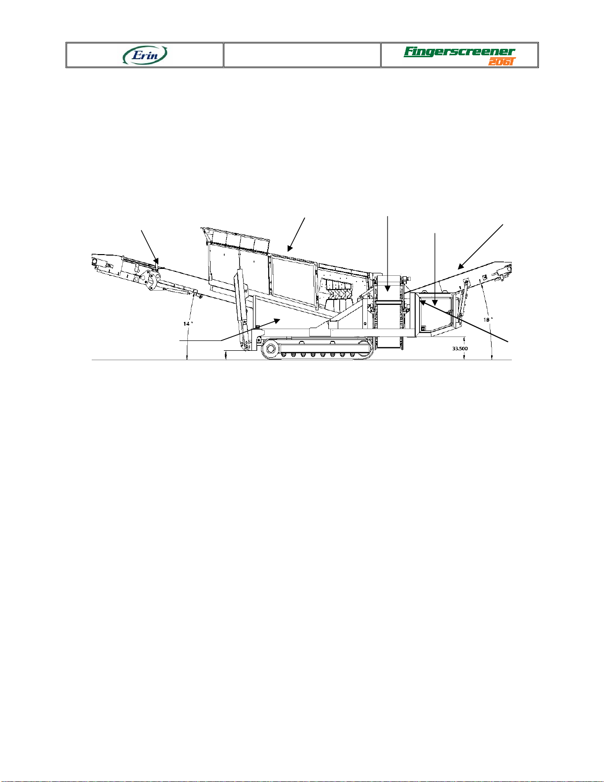
Figure 2-1 FS-206T General view
2.2.1 Description of the Screen Box
The Erin Fingerscreener FS206T is fitted with a 20 feet (6.1 m) long and 5.5 feet (1.68 m)
wide lengthwise double deck Screen Box (1) as standard. The Screen Box is a two bearing
arrangement mounted on low noise rubber anti-vibration units. It can be loaded using wheel
loaders, backhoe, excavator or directly via a conveyor. Two decks of fingers are disposed on
the structure: the top deck is fitted with heavy duty Grizzly™ fingers and the bottom deck
with medium duty Cascade™ fingers, with openings to suit customer requirements. You can
hydraulically raise or lower the Screen Box at 10°, 13˚or 16°to retain less or more of the
material that is being screened. Finger sections can also be moved up and down to control
material flow and clearance. You can adjust the Cascade™ fingers up to slow material down
or down to speed it up.
2.2.2 Description of Stockpile Conveyors
The Fingerscreener FS206T has a 1.52 m (60 inches) wide belt Fine Stacker (5). It also has a
1.52 m (60 inches) wide belt Reject Stacker (2) and a 0.91 m (36 inches) wide chevron belt
Middle Stacker (4). Those conveyors are hydraulically foldable for transportation. Each
conveyor is powered by a hydraulic motor drive coupled to a drive drum. Belt scrapers are
fitted as standard.
Screen Box (1) Reject Stacker (2)
Power Pack (3)
Fine Stacker (5)
Middle Stacker (4)
(optional)
Main Frame (6)
FRONT
REAR
Serial number location
(opposite side)

Description
Rev: 0-3 (international, serial no. 3010) - 2-3 - May 2006
2.2.3 Description of the Main Frame
The Erin Fingerscreener FS206T is powered by a diesel engine located at the end of the
machine in the Power Pack. The hydraulic tank is also in the Power Pack.
The machine is designed to be transported on a 0.6 m (2 feet) high low-bed semi-trailer. Its
traveling width is 3 m (9’ 10”).
The Fingerscreener FS206T compact design minimizes set-up time and offers the customer
unrestricted flexibility when transporting equipment around the site or to individual sites.
2.3 Technical File
Type of material to screen: topsoil, landfills, recycling, compost, sand and gravel, construction
and demolition waste, soil clean-up, land clearing, trash, scrap metal and incinerator waste.
Please note that all tons are metric (1000 kg or 2200 lb).
-Serial number location: Refer to Figure 2-1 FS-206T General view
-Traveling length: 17.37 m (57’-0”)
-Traveling height: 3.41 m (11’-2”)
-Traveling width: 3.44 m (11’-3”)
-Operating length (max): 18.75 m (61’-5”)
-Operating height (max): 5.30 m (17’-4”)
-Loading height (max): 4.94 m (16’-2”)
-Operating width: 3.44 m (11’-3”)
-Total weight: 87 200 pounds (39 553 kg) approx.
-Tracks: Width of shoe: 500 mm (19.68”)
Pitch: 3,800 mm (139 5/8”)
-Diesel engine: 4 cylinders, EPA emission approved
106 kW (142 HP) CAT 3054E Turbo
-Diesel tank: 335 litres (88 gallons) approx.
-Total number of hydraulic pumps: 3
-Total number of hydraulic motors: 5
-Hydraulic oil tank: 425 litres (112 gallons) approx.
-Total number of belts: 2
-Dimension of belt on Reject Stacker: chevron, 1524 mm (60”) 3 plies,
4.7 mm-1.6 mm (3/16”- 1/16”)
speed up to 0.78 m/s (155 FPM)
-Reject Stacker stockpiling height in two-product mode: 4.11 m (13’-5”)
-Reject Stacker stockpiling height in three-product mode: N/A
Table of contents


