FläktGroup SEMCO Ascendant User manual

OWNER’S MANUAL
SPECIALIZED
HEALTHY
AIR SOLUTION
S

1ii
SPECIALIZED
HEALTHY
AIR SOLUTION
S
SPECIALIZED
HEALTHY
AIR SOLUTION
S
OWNER’S MANUAL OWNER’S MANUAL
ASCENDANT™ASCENDANT™
Introduction ................................1
The FläktGroup SEMCO System.................1
System Installation ..........................3
Lifting .................................3
Receiving...............................3
Inspection ..............................4
Storage ................................4
Installation. . . . . . . . . . . . . . . . . . . . . . . . . . . . . . 4
Mounting Details, Curb Support .............9
Mounting Details, Grid or Pad Support .......10
Active Desiccant Wheel ......................11
Fans......................................11
Dampers .................................12
Coils.....................................13
Air Filters.................................13
Unit Control ...............................16
Sequence of Operation ...................16
Programming Parameters.................16
Troubleshooting ............................19
Maintenance ..............................21
© SEMCO 2015-2021. All rights reserved.
The information in this owner’s manual is furnished for informational use only, is subject to change without notice, and should not be
construed as a commitment by SEMCO LLC. SEMCO LLC assumes no responsibility for any errors that may appear in this owner’s manual.
No part of this publication may be reproduced, stored in a retrieval system or transmitted, in any form or by any means, electronic,
mechanical, recording, or otherwise, without the prior written permission of SEMCO LLC.
© SEMCO LLC 2021 All Rights Reserved. SEMCO and the SEMCO logo are registered Trademarks of SEMCO LLC.
This manual describes how to erect, store, clean and
maintain a FläktGroup SEMCO Ascendant™ Series
Active Desiccant System.
Each section provides information to guide the
installation and maintenance of all components that
may be included in the system. However, some
individuals may desire more information about one or
more items of equipment installed in the system. If so,
consult the manufacturer’s manual that accompanies
the equipment or is included with our submittal.
It should also be noted that a section or sections
of this manual might not apply to your system; for
example, it may not include a chilled water or steam
coil. The manual has been prepared to cover the basic
system as well common optional components that may
be included in an Ascendant Series Active Desiccant
System.
INTRODUCTION
THE FLÄKTGROUP SEMCO
SYSTEM
TABLE OF CONTENTS
The Ascendant™ Series is a conventional cooling –
active desiccant hybrid system. Performance is
optimized to deliver and control low dew point air while
minimizing energy input. The system is configurable
as a dedicated outdoor air system (DOAS) or a
recirculated air system.
The heart of this system is a technologically advanced
desiccant wheel. This wheel is constructed of inorganic
and incombustible materials in a honeycomb pattern to
lower pressure drop, thereby saving fan energy.
The Ascendant™ system processes outdoor and/
or return air streams to a moderate leaving coil
temperature condition (when needed), thereby
delivering saturated air to the active desiccant wheel
which promotes highly efficient moisture adsorption,
further depressing the supply air humidity content to
very low dew points.
By employing moderate chilled water or refrigerant
temperatures, the efficiency of the cooling system
employed is high.
An integral modulating bypass damper allows the
cool, moderately dry air leaving the cooling coil to be
mixed with the appropriate quantity of warm, very dry
air leaving the dehumidification wheel to deliver the
required supply air dew point. If tight temperature
control is also required, a small sensible only post
cooling coil is employed.
Regeneration of the desiccant wheel is also achieved
with high energy efficiency. A typical regeneration
airflow quantity is only 20% - 40% of the supply airflow
volume. Only moderate regeneration temperatures
(140˚F to a maximum of 200˚F.) are required, allowing
the use of hot water, steam, direct or indirect fired gas,
or electric heat.
For applications where an exhaust air stream
is available (i.e. hospital operating theaters)
preconditioning the outdoor air with FläktGroup SEMCO
total energy recovery is highly recommended since
it substantially increases overall system energy
efficiency and substantially reduces pre-cooling input
requirements. It also provides valuable winter season
preheat and humidification.
On the supply air side of the wheel, a chilled water or
direct expansion coil provides cool, moist air to the
wheel. The wheel adsorbs the moisture, producing
dry supply air. On the regeneration side of the wheel,
warm, dry air enters the wheel, which desorbs the
moisture allowing it to be exhausted from the system.

32
SPECIALIZED
HEALTHY
AIR SOLUTION
S
SPECIALIZED
HEALTHY
AIR SOLUTION
S
OWNER’S MANUAL OWNER’S MANUAL
ASCENDANT™ASCENDANT™
FOUR STEPS TO FRESH, COOL AIR DURING THE COOLING SEASON:
LIFTING
FIGURE 1. Lift modules only with lugs located at the base of
each module. Do not use a forklift.
To off load each of the system’s modules, lift only
with the lugs located at the base of each module
(FIGURE 1). Do NOT lift with a forklift. Spreader bars
must be used to hoist sections to avoid damaging
the enclosure (FIGURE 2).
SYSTEM INSTALLATION
How to handle the system upon delivery to the project site.
FIGURE 2. Spreader bars must be used for hoisting modules
to avoid damaging the enclosure.
Bypass Damper
Active
Dehumidification
Wheel
Regeneration
HeaterRegen Fan
Cooling Coil
Supply Fan
Regen Out
Regeneration Outdoor Air
Outdoor Air
Dehumidified Air
Bypass Air
Supply Air
1
2
3
4
1
2
3
SUPPLY
SIDE
REGENERATION
SIDE
Post Cooling
Coil
(Optional)
4
SUPPLY SIDE REGENERATION SIDE
STEP 1
Hot, humid outside air is drawn into the
Ascendant system passing through pre-filters
before entering conditioning components.
Hot, humid outside air is drawn into the Ascendant
system passing through pre-filters before entering
conditioning components.
STEP 2 Outside air is cooled and dehumidified before
entering the Active Desiccant wheel.
Outside air is heated to desired temperature to
lower the relative humidity of the air before entering
the Active Desiccant wheel.
STEP 3
The moisture in the air is adsorbed by the
desiccant producing dry air. A modulating damper
allows a portion of the supply air to bypass the
wheel.
The adsorbed moisture is desorbed by heated
air regenerating the wheel’s ability to remove
moisture.
STEP 4
(OPTIONAL) Supply air can be cooled using
post-cooling coils and further filtered with high
efficiency or HEPA filters.
Warm, humidified regeneration air is exhausted
from system.
Chokers need to be adjustable so that the unit is
level when it is picked up and, more importantly,
set down. Setting the unit down on one corner could
cause the unit to rack. Lever chain pullers are useful
for this purpose.
RECEIVING
1) A packing list is supplied with each shipped
system (See FIGURE 3). The list should be
compared with arriving shipments to ensure that
all modules and equipment have been delivered
in good condition. Visible damage should be
noted on the trucker’s bill of lading when
receiving the unit.
2) Prior to leaving the plant, each system has been
tested. You will find the quality assurance label
on the inside of the electric box cover.
3) If the modules are to be stored for more than
three days prior to installation, a visual
inspection of all equipment is necessary. Report
missing or damaged equipment to FläktGroup
SEMCO immediately. Freight claims are difficult
to justify long after delivery has been completed.
(If the modules are to be stored, see STORAGE
on PAGE 4.
4) Modules accumulate dust, dirt and corrosive
matter (like salt) during shipment to the
installation, site on open trailers, and are
FIGURE 3. An envelope with the packing list and other
pertinent information is found inside the electrical box.

54
SPECIALIZED
HEALTHY
AIR SOLUTION
S
SPECIALIZED
HEALTHY
AIR SOLUTION
S
OWNER’S MANUAL OWNER’S MANUAL
ASCENDANT™ASCENDANT™
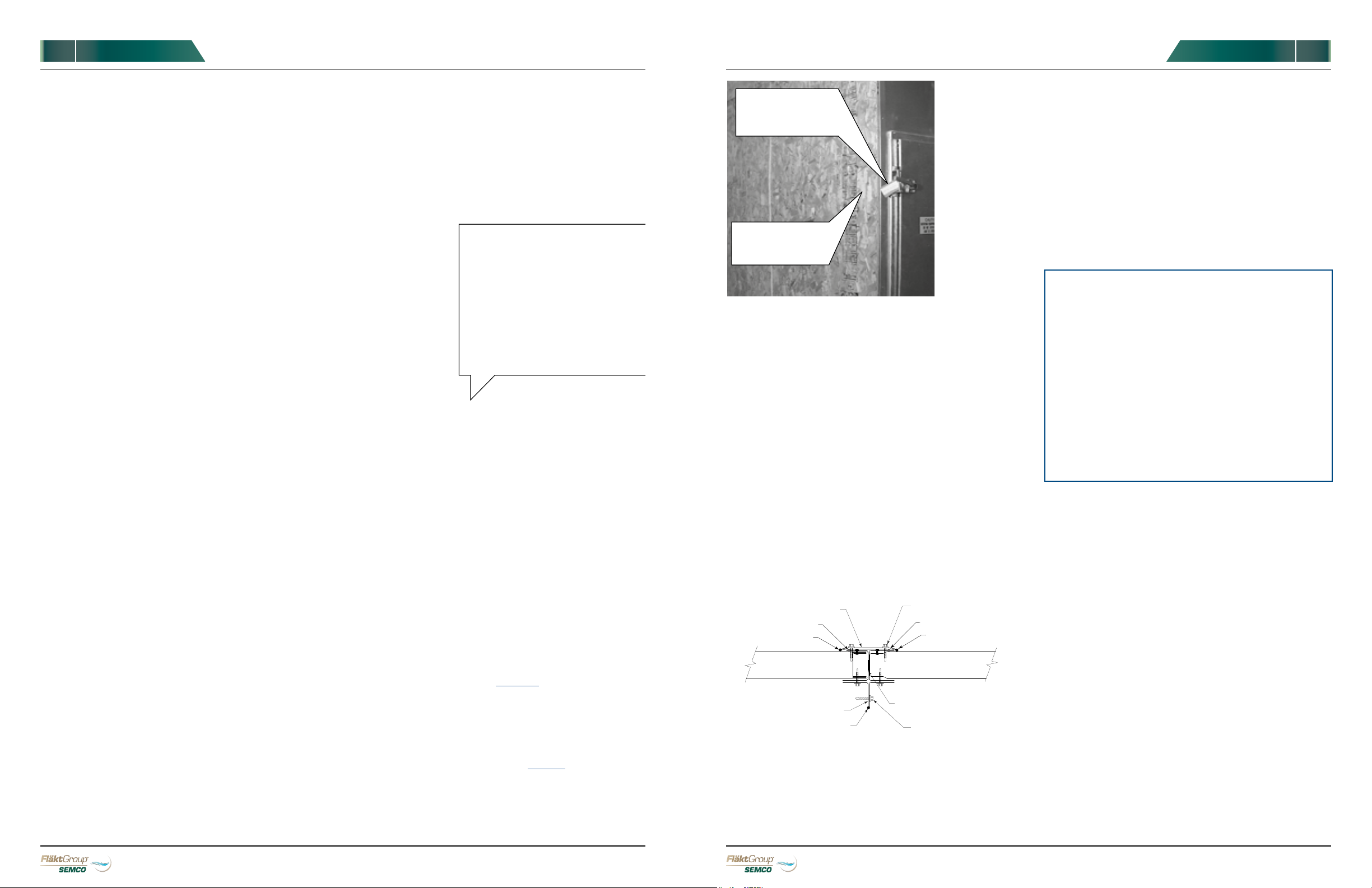
FIGURE 4. All gaskets, bolts, and other items required for
installation are shipped in a box located in the supply air
compartment. On top of the box you will find a packing list.
STORAGE
INSPECTION
In addition to inspecting modules and equipment
visually for possible shipping damage, be sure to
consult “Inspection” instructions described later in this
manual for each optional component.
exposed to still more grime on the construction
site. Therefore, it is imperative that the exterior
of each module be washed down with soap and
water soon after it arrives. Abrasives and solvents
should not be used without first consulting
FläktGroup SEMCO.
4) The interior of each module should also be
cleaned throughly and all equipment should be
lubricated before storing or beginning operation.
5) See other sections for specific lubrication
instructions.
If the system, or parts thereof, must be stored before
installation, indoor storage is preferred. If not possible,
modules should be located on a hard surface with
adequate drainage so that water cannot accumulate
under the modules. A solid paved surface would be
appropriate. Modules must be stored on blocks or
timbers that raise modules at least four inches above
the ground.
If stored indoors, modules should be protected from
damage. If stored outdoors, modules must be covered
with well-anchored canvas tarps. Heavy-mil plastic
tarps should be used with caution as they can trap
moisture against the unit.
MOISTURE MUST NOT BE ALLOWED TO ENTER THE
MODULES. Whether stored indoors or outdoors,
all openings must be closed tightly and piping
penetrations must be capped. However, drain
connections should be left open.
As noted previously, modules must be washed to
remove corrosive materials and dirt before storage.
During the storage period, modules should be opened
and inspected every 30 days. Fans must be inspected
and rotated a few times by hand and stopped in a
position other than the original position. Fans should
also be lubricated as prescribed on the fan label.
INSTALLATION
1) Prepare the installation site by cleaning it of all
debris. Supports, which the modules will be
installed on, should be level. The unit base is
designed either for mounting on a concrete pad or
onto a roof curb (See PAGE 10).
2) Consult drawings and submittal provided to
determine the location of each module. Plan to
lift modules in the order required for your
Installation and within the limitations of your lifting
equipment (see LIFTING on PAGE 3).
3) Adjoining ends of modules are covered with
plywood and/or plastic sheets during transport.
This must be removed prior to hoisting the
modules in place. (See FIGURE 6).If installation
FIGURE 5.
Module sides which are to be joined at time of installation are
covered with plywood and/or plastic sheets for protection
during transport.
Throughout the unit you will find instruction labels indicating
which steps MUST be performed for proper installation.
4) Remove shipping restraints at roof joint (not
shown).
5) Hoist the first module in place. Spreader bars and
hoisting lugs must be used on each module for
hoisting. Do not use forklifts. (See FIGURES 1 and 2
on PAGE 3).
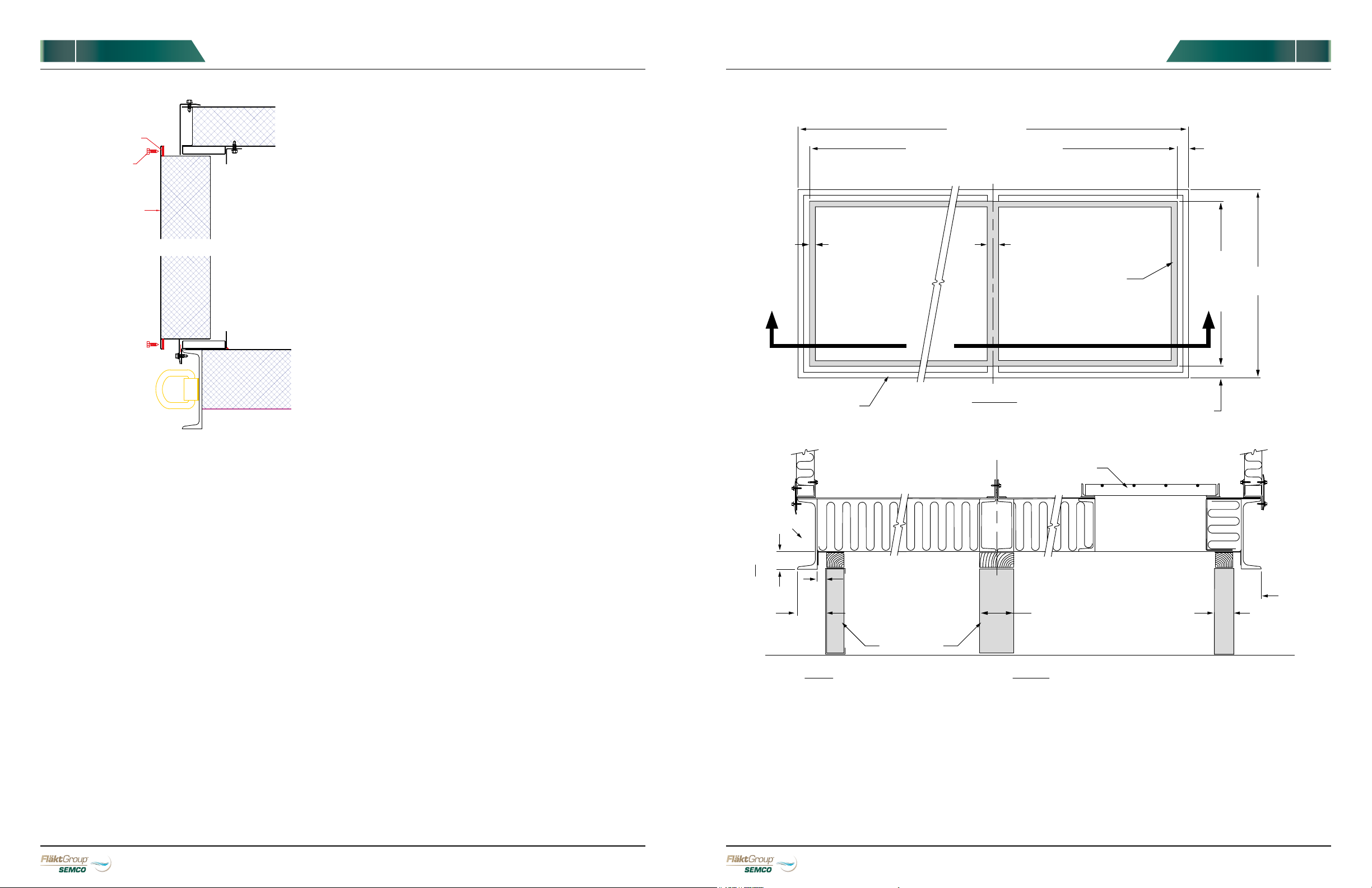
6) After positioning the module correctly, install
continuous gasket material on field joint flange as
indicated in FIGURE 6.
INSTRUCTION
LABEL
REMOVE
BEFORE
INSTALLATION
BUTT STRAP TEK SCREW 12" O.C.
POLYURETHANE CAULK
POLYURETHANE CAULK
PANEL
GASKET BETWEEN JOINT
TEK SCREW 12" O.C.
POLYURETHANE CAULK
POLYURETHANE CAULK
POLYURETHANE CAULK
PANEL
GASKET
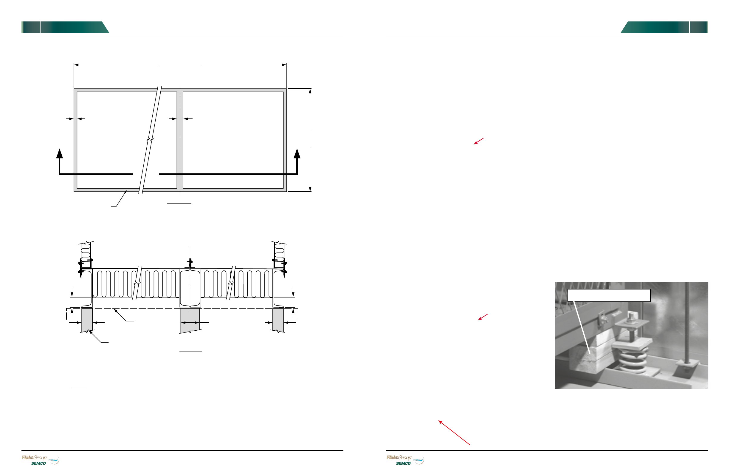
FIGURE 6. Detail of field joint located on side.
FIGURE 7. Field joint located on base. Use only these bolts to
pull the modules together!
7) Hoist the second module by its lifting lugs
(continue to use spreader bars), and position it
close to the first module. After aligning with the
first module, move the second module against the
first module.
8) Insert bolts that join the first two modules in the
unit base and tighten. The large bolts in the unit
base may be used to help pull the two modules
against each other. Do not use any of the internal
field joints to pull the units together.
(See FIGURE 7).
9) Verify that the two modules are straight, square
and level. Use metal shims if necessary to level.
10) Hoist and set succeeding modules as described
in STEPS 5-7.
If moisture is found in any module, it must be removed
immediately. The source of the moisture must be
determined and corrected immediately.
During storage, modules should not be stacked on top
of each other.
Boxes containing bolts, gaskets and other items
should be stored inside the modules (See FIGURE 4).
11) If installation requires that some modules be
placed on top of base or bottom modules, be sure
to install continuous gaskets between upper
and lower modules as indicated in drawings and
submittals.
12) Do not torque connecting bolts until all upper
modules are installed. Experience suggests
installing bolts in the following manner. First,
attach bolts that join the centers of connecting
modules. Then work outward from the center
and attach remaining bolts, which will assure
proper alignment. Bolts should only be tightened
by hand until all upper modules are in place.
Then they should be torqued to 25 ft-lbs.

76
SPECIALIZED
HEALTHY
AIR SOLUTION
S
SPECIALIZED
HEALTHY
AIR SOLUTION
S
OWNER’S MANUAL OWNER’S MANUAL
ASCENDANT™ASCENDANT™
FIGURE 9. Field joint located at floor.
BUTT STRAP
3/4"-10 NUT
FLAT WASHER
1/2'' THICK BAR STOCK
FIELD
JOINT
C8 x 11.5 CHANNEL
3/4"-10 BOLT
2 1/2" LONG
FLAT WASHER
FIGURE 8. Detailed drawing of field joint.
FIGURE 10
FIGURE 11
FIGURE 12
FIGURE 13
FIGURE 14
FIGURE 15
13) Complete field joint assembly by applying
polyurethane caulk to the exterior of the joint and
then cover with butt strap as shown in FIGURE 6
(on PAGE 5), FIGURE 8 and FIGURE 9.
14) Modules produced for outdoor locations are
manufactured with a galvanized steel standing
seam roof. A section of roof is shipped loose for
field installation at each field job.
Caulk this edge on both sides of
the unit before installing metal
15) Apply polyurethane caulk along the underside
of the roof butt strap and center over the joint
Slide edge of roof panel
under J portion of roof.
between the two modules. Using #12 TEK screws
at approximately 12” centers, screw the butt strap
to the roof.
Caulk, drill and pop rivet to
close/seal end of panel.
Crimp roof lips
after installation
Install butt strap over joint –
caulk and screw in place
(butt strap not shown)
First Foam Panel
16) Apply caulk at high and low point of roof and add
first foam panel.
17) Apply second foam panel. (See FIGURE 14 picture
for caulking instructions).
18) Insert one edge of roof panel as shown and
rotate into place (See FIGURE 13).
Raincap
19) Crimp roof lips with crimping tool (See FIGURE 14).
20) Finish high side of roof with rain cap. Screw in
place similar to factory cap.
21) Holes for conduit, piping, etc., are normally
precut in module panels at the factory. However,
if it is necessary to change the location of a
hole or to cut a new one, these guidelines must
be observed:
• Every hole represents a potential leak. Avoid
adding new holes to the enclosure if possible.
• If it is necessary to add a new hole or to
move the location of a hole already in the unit,
select a location as close as possible to
hookup inside the enclosure.
•Cut holes through panels. DO NOT cut through
structural members.
22) Removable panels are furnished for large items
such as coils. Adequate service space in front of
these panels should be provided in case the item
or items will have to be removed at some future
time (See FIGURE 16 on PAGE 8 ).

8
SPECIALIZED
HEALTHY
AIR SOLUTION
S
OWNER’S MANUAL
ASCENDANT™
FIGURE 17. Inside the electrical box cover you will find a
wiring schematic, and the quality assurance label.
PAN HEAD SCREW
GASKET
PANEL
REMOVABLE
FIGURE 16. Detailed drawing of removable panel installation.
23) Complete electrical and control connections
across field joints. Use coded wires or terminal
strips in junction boxes and the flex connections
provided. Wiring diagrams are attached to the
inside of the electrical panel (See FIGURE 17).
24) Complete service connections to piping and
power. Be certain to check specific requirements
for electrical power to the energy recovery unit,
fans, dampers and other electrical devices.
25) For components, please reference instructions
in the following sections of this manual before
proceeding.
9
SPECIALIZED
HEALTHY
AIR SOLUTION
S
OWNER’S MANUAL
ASCENDANT™
MOUNTING DETAILS, CURB SUPPORT
SELF FLASHING UNIT BASE
SHOWING CURB SUPPORT REQUIREMENTS
UNIT LENGTH
CURB
PERIMETER
UNIT PERIMETER
CURB LENGTH = UNIT LENGTH - 6 ½"
SECTION
TYPICAL UNIT WITH CURB SUPPORT
PLAN VIEW
CURB
WIDTH =
UNIT
WIDTH -
6½"
UNIT
WIDTH
3 ¼"
TYPICAL BOTH
ENDS
4"
MINIMUM
SUPPORT AT
FIELD JOINTS
2"
MAXIMUM
SUPPORT ON
UNITS WITH FLOOR
OPNGS.
NOTES
1. ROOF CURB SHOULD BE SIZED TO
ALLOW UNIT TO HANG OVER CURB.
2. CURB SIZE:
WIDTH = UNIT WIDTH - 6.5"
LENGTH = UNIT LENGTH -6.5"
3. UNIT SUPPORT IS REQUIRED
AROUND THE ENTIRE PERIMETER
AND ALONG BOTH SIDES OF ANY
FIELD JOINTS.
4. WHEN UNITS REQUIRE FIELD JOINTS,
SUPPORT SHOULD BE LEVEL TO
1/16" BETWEEN FIELD JOINTS.
3¼"
TYPICAL BOTH
SIDES
2" WIDE SUPPORT AT UNIT
PERIMETER
FIELD JOINT
CENTERLINE
FIELD
JOINT
FLOOR GRATE
FLOOR
OPENING
3 ¼"
3 ¼"
CURB (BY OTHERS)
1"
2"
4" WIDE MINIMUM
SUPPORT AT FIELD
JOINTS

1110
SPECIALIZED
HEALTHY
AIR SOLUTION
S
SPECIALIZED
HEALTHY
AIR SOLUTION
S
OWNER’S MANUAL OWNER’S MANUAL
ASCENDANT™ASCENDANT™
SPECIALIZED
HEALTHY
AIR SOLUTION
S
OWNER’S MANUAL
All necessary active desiccant wheel components
have been installed at the factory and tested for
proper operation prior to shipping. Before start up,
the following steps should be taken:
1) Pump grease into the two rotor bearing grease
fittings using a high quality NLGI No. 2 grease
(See FIGURE 18).
ACTIVE DESICCANT WHEEL
FIGURE 21. Fan shipping restraints located at the base of
the fan.
Remove wooden blocks
All necessary system fans and fan motors are installed
at the FläktGroup SEMCO factory. However, before
attempting to operate them, a pre-startup inspection is
recommended.
1) Make sure all power to the fan motors is off.
2) Remove wooden blocks and any shipping
restraints and discard (See FIGURE 21).
FANS
FIGURE 18. Pump
grease into two
rotor bearing
grease points, one
on each side of
the rotor.
FIGURE 20. The
bearing set
screws, one on
each side of the
rotor, should
be checked for
tightness every
six months.
FIGURE 19.
Inspect bearing
collar to ensure
all bolts and
screws are tight.
2) Inspect the rotor visually. It should be well
centered in its casing and should not tilt in any
one direction. If alignment is not suitable, contact
FläktGroup SEMCO.
3) Inspect the bearing bolts and the Allen screws
on the bearing collar to ensure that all are tight
(See FIGURE 19). Tighten any loose screws and
bolts. The bearing bolts should be torqued to 50
ft-lbs. The bearing set screws should be torqued
to 15 ft-lbs.
4) The bearing set screws should be checked
periodically for tightness. A bearing set screw is
located on each side of the rotor (See FIGURE 20).
5) The bearing set screws should be torqued to
15 ft-lbs.
6) Upon unit startup observe the wheel in operation
and verify that the rotor does not bind. If binding
occurs in a new unit, it is usually caused by the
seal or freight damage.
ADJUSTING THE SEALS
Maintaining correct seal adjustment is vital to the
effective operation of the unit. The face and perimeter
seals are designed to gently contact the face of the
wheel and wheel rim angle to prevent air from leaking
across or around the wheel sections. Adjustment of the
seals is simply done by loosening the screws holding the
seal clips in place, adjusting the seal so it just contacts
the surface of the wheel/rim, and then re-tightening the
screws.
3) Inspect the fans:
•Check fan bolts and mountings for tightness.
Tighten loose screws and bolts.
SECTION
UNIT BASE WHEN MOUNTING
ON PAD OR STRUCTURAL GRID
PLAN VIEW
TYPICAL UNIT WITH HOUSEKEEPING PAD
OR STRUCTURAL GRID SUPPORT
UNIT LENGTH
UNIT PERIMETER
UNIT
WIDTH
4"
MINIMUM
SUPPORT AT
FIELD JOINTS
2"
MINIMUM
SUPPORT AT
UNIT PERIMETER
2"
MINIMUM
SUPPORT AT
UNIT PERIMETER
NOTES
1. UNIT SUPPORT IS REQUIRED
AROUND THE ENTIRE
PERIMETER AND ALONG BOTH
SIDES OF ANY FIELD JOINTS.
2. WHEN UNITS REQUIRE FIELD
JOINTS, SUPPORT SHOULD BE
LEVEL TO 1/16" BETWEEN FIELD
JOINTS.
2" WIDE SUPPORT AT
UNIT PERIMETER
FIELD JOINT
CENTERLINE
FIELD
JOINT
CONCRETE PAD
(BY OTHERS)
2"2"
4" WIDE MINIMUM
SUPPORT AT
FIELD JOINTS
STRUCTURAL GRID
(BY OTHERS)
MOUNTING DETAILS, GRID OR PAD SUPPORT

1312
SPECIALIZED
HEALTHY
AIR SOLUTION
S
SPECIALIZED
HEALTHY
AIR SOLUTION
S
OWNER’S MANUAL OWNER’S MANUAL
ASCENDANT™ASCENDANT™
SPECIALIZED
HEALTHY
AIR SOLUTION
S
OWNER’S MANUAL
Heating and/or cooling coils can be ordered with the
energy recovery system. All necessary heating and/
or cooling coils have been installed at the FläktGroup
SEMCO factory. However, before operating them, a brief
pre-startup inspection is recommended.
INSPECTION
• Inspect all pipe connections to verify they are tight
and that no damage has occurred during transit or
on-site installation.
•STEAM COILS – Be sure that the unit is level so the
coils inside the casing slope toward the header.
• HOT WATER COILS – Check the freeze protection
thermostat for proper operation so that it will
function to prevent freeze-ups.
OPERATION
•STEAM COILS – Non-freeze steam coils are
designed to operate steam pressures up to, and
including, 150 psig and temperatures to 350°F.
•During initial operation, make sure that
condensate flows back to the headers. Check for
leaks.
•HOT WATER COILS - are designed to operate at
pressures to 150 psig, and temperatures to
366°F. Check for leaks during initial operation.
• COOLING COILS -are designed to withstand
pressures to 200 psig. During initial operation,
check for leaks (See FIGURE 25).
COILS
FIGURE 25. Cooling coils should be checked for leaks during
operation.
3) The dampers are controlled by electric motors.
Make sure that wiring is complete. Check the
wiring diagram on the motor.
4) Turn on power and observe whether or not the
controls trigger dampers correctly. Be sure that
limit switches close when blades are open and
open when blades are closed.
AIR FILTERS
Air filters for the energy recovery system are boxed,
tagged and shipped loose inside the system for field
installation. This minimizes any risk for filter damage
during transit. The air filters must place installed prior
to startup or the warranty could be voided.
Throughout the operating life of the system, it will be
necessary to replace filters as they accumulate dirt
from the air stream.
The system is equipped with two pressure differential
gauges. As air filters accumulate dirt, the pressure
differential will rise.
The PRE-FILTER CAPACITY AND RESISTANCE TABLE
(FIGURE 26) and FINAL FILTER CAPACITY AND
RESISTANCE TABLE (FIGURE 27) provide data for most
pre-filters and final filters used in FläktGroup SEMCO
systems. For each filter size, the pressure differential
(resistance at capacity) using new, clean air filters in
air streams is shown. The capacities columns define
airflow in cubic feet per minute. For specific airflows,
interpolating and estimating will provide adequate
data.
SPECIALIZED
HEALTHY
AIR SOLUTION
S
OWNER’S MANUAL
FIGURE 22. As an option, the fans can be mounted on seismic
arrest mounts.
•Rotate the impeller by hand; it should turn freely.
If not, check for obstructions and contact
FläktGroup SEMCO (see the BACK COVER for
contact info.).
•Ensure that the fan wheel and fan interior are
clean are free of debris.
•Check fan set screw for tightness; re-tighten if
necessary.
4) After completing inspection checks on motors and
fans, turn power on then off quickly. Power should
be on just long enough to start fan rotation.
5) If fans start rotating in the wrong direction (See
ARROW ON THE BLOWER) turn off power
immediately. To correct rotation, lock out power to
the unit feeder, and switch any two line power
wires. To change rotation of only an inverter driven
wheel and not the fans, switch any two VFD line
power wires.
6) Using an amp probe or amp meter, check the
actual operating current of the motor to make
sure it is not being overloaded or underpowered.
The operating current must not exceed the
nameplate current.
7) Allow the assembly to run for about an hour. During
this time, listen for any unusual sounds. To correct
noise problems, see TROUBLESHOOTING on
PAGE 19.
OPTIONAL FAN MOUNT
DAMPERS
While they have been installed and checked at the
FläktGroup SEMCO factory, a pre-startup inspection
is recommended to be sure that nothing has become
detached or damaged during shipment or on-site
installation.
INSPECTION
1) Check blade rotation clearance. Verify that blades
open and close properly and rotate sufficiently.
If they do not, check for obstructions, broken or
bent blades, or loose linkage. Correct or repair as
necessary (See FIGURE 23).
FIGURE 23. Be sure that damper blades open
and close properly and have sufficient rotation
clearance.
2) Be sure that actuator arms and bars connecting
damper motors to control rods or shafts are tight.
(See FIGURE 24).
FIGURE 24. Damper actuator.

1514
SPECIALIZED
HEALTHY
AIR SOLUTION
S
SPECIALIZED
HEALTHY
AIR SOLUTION
S
OWNER’S MANUAL OWNER’S MANUAL
ASCENDANT™ASCENDANT™
SPECIALIZED
HEALTHY
AIR SOLUTION
S
OWNER’S MANUAL
FIGURE 28. Quantity and size of filters in standard units
WHEN TO REPLACE FILTERS
MODEL SIZE
SIZE 5 SIZE 9 SIZE 13 SIZE 18 SIZE 24
SA FILTER
QTY AND
SIZE
24" x 24" (4) 24" x 24" (4) 24" x 24" (6) 24" x 24" (9) 24" x 24" (12)
— 12" x 24" (4) 12" x 24" (3) 12" x 24" (3) 12" x 24" (4)
EA FILTER
QTY AND
SIZE
24" x 24" (2) 24" x 24" (2) 24" x 24" (3) 24" x 24" (6) 24" x 24" (8)
12" x 24" (2) 12" x 24" (3) 12" x 24" (3) 12" x 24" (2) —
It is recommended that filters be changed when the
pressure differential gauge reaches the final resistance
rating illustrated in FIGURE 26 and FIGURE 27 (on PAGE
14). Experience with the new system may suggest
changing filters at a slightly higher or lower reading.
Depending upon the total volume of air required in
the building, altering the replacement differential may
be necessary. But waiting to change filters when the
pressure differential reaches or approaches a higher-
than-recommended figure would mean using packed
air filters that seriously reduce airflow.
If the system is ordered with final filters, then these will
be located behind the pre-filters.
The procedure for removing the old filters and installing
new ones is the same as described on PAGES 5and 6.
For systems equipped with pre-filter and final filter
banks, it is recommended that pre-filter banks be
changed twice as often as final filters.
For air filter replacement, a rigid, cell-type filter that
matches the specifications shown in the PRE-FILTER
AND FINAL FILTER CAPACITY AND RESISTANCE TABLES
is recommended.
SPECIALIZED
HEALTHY
AIR SOLUTION
S
OWNER’S MANUAL
FIGURE 26. Pre-filter Capacity and Resistance Data
• PRE-FILTER CAPACITY AND RESISTANCE DATA
FILTER
DEPTH
NOMINAL
SIZE
(INCHES)
ACTUAL SIZE
(INCHES) CAPACITIES (CFM) RESISTANCE AT CAPACITY
(INCHES W.G)
WIDTH HEIGHT DEPTH MEDIUM HIGH MEDIUM HIGH FINAL
4"
12x24x4 11.38 23.38 3.88 600 1,200 0.12 0.35 0.90
24x24x4 23.38 23.38 3.88 1,200 2,400 0.12 0.35 0.90
2"
12x24x2 11.38 23.38 1.88 500 1,000 0.08 0.28 0.90
12x24x2 23.38 23.38 1.88 1,000 2,000 0.08 0.28 0.90
12" FINAL FILTER CAPACITY AND RESISTANCE DATA*
FILTER MEDIA
EFFICIENCY
NOMINAL SIZE
(INCHES)
ACTUAL SIZE1
(INCHES) AIRFLOW CAPACITY
(CFM)
RESISTANCE (IN.WG.)
WIDTH HEIGHT INITIAL FINAL2
60-65%
12x24 11.38 23.38 1,000 0.29 1.5
24x24 23.38 23.38 2,000 0.29 1.5
80-85%
12x24 11.38 23.38 1,000 0.50 1.5
24x24 23.38 23.38 2,000 0.50 1.5
90-95%
12x24 11.38 23.38 1,000 0.68 1.5
24x24 23.38 23.38 2,000 0.68 1.5
FIGURE 27. 12” Final Filter Capacity & Resistance Data
*NOTES:
1) Actual depth of the 12" filter is 11.50"
2) Maximum recommended final resistance. System design may require a lower change-out reistance.
Maximum operating temperature limit for the filters is 180ºF in continuous operation and 200ºF in intermittent operation.

1716
SPECIALIZED
HEALTHY
AIR SOLUTION
S
SPECIALIZED
HEALTHY
AIR SOLUTION
S
OWNER’S MANUAL OWNER’S MANUAL
ASCENDANT™ASCENDANT™
SPECIALIZED
HEALTHY
AIR SOLUTION
S
OWNER’S MANUAL
PARAM.
TITLE FUNCTION OPTIONS DEFAULT
SETTING
SEMCO
SETTING COMMENTS
B1-01 Frequency
Reference
Selection 1
0: Operator - Digital preset speed d1-
01 to d1-17.
1: Terminals - Analog input terminal A1
or A2.
2: MEMOBUS communications
3: Option PCB
4: Pulse Input (Terminal RP)
1 1 Selects the frequency
reference input source.
B1-02 Run Command
Selection 1
0: Operator - RUN and STOP keys on
the digital operator.
1: Digital input terminals
2: MEMOBUS communications
3: Option PCB
1 1 Selects the run command
input source.
B1-04 Reverse Operation
Selection
0: Reverse enabled.
1: Reverse disabled.
0 1 Permits or prohibits reverse
operation.
B1-07 Local / Remote
Run
0: Run command must be cycled
1: Continue running
0 1 Drives run if run command
is active in new controller
B1-17 Run Command at
Power Up
0: Run command must be cycled
1: Run command issued
0 1 Drive runs if run command
is active at power up
C1-01 Acceleration Time 0.0 to 6000.0 10 60 Acceleration time
C1-02 Deceleration Time 0.0 to 6000.0 10 60 Deceleration time
C4-01 Torque
Compensation Gain
0.00 to 2.50 1 0 Compensates for added
load by increasing output
voltage.
C6-02 Carrier Frequency
Selection
1 : 2.0 kHz
2 : 5.0 kHz
3 : 8.0 kHz
4 : 10.0 kHz
5 : 12.5 kHz
6 : 15.0 kHz
7 : Swing PWM1 (Audible sound 1)
8 : Swing PWM2 (Audible sound 2)
9 : Swing PWM3 (Audible sound 3)
A : Swing PWM4 (Audible sound 4)
B to E: No setting possible
F : User defined (determined by C6-03
through C6-05)
3 1 Lower carrier frequencies
increase torque and audible
noise.
E1-03 V/f Pattern
Selection
0 to FF F F Allows custom voltage
frequency curve.
E2-01 Motor Rated
Current
10 to 200% of drive rated current kVA
dependent
0.57
(208-230)
0.29 (460)
E2-03 Motor No-Load
Current
0 to [E2-01] kVA
dependent
0.23
(208-230)
.11 (460)
Nameplate amps * 40%
Consult SEMCO
PROGRAMMING PARAMETERS
*FläktGroup SEMCO does not recommend use with motors other than those provided with the unit. Consult Yaskawa for assistance
in programming for use with other motors.
SPECIALIZED
HEALTHY
AIR SOLUTION
S
OWNER’S MANUAL
UNIT CONTROLS
PROGRAMMING PARAMETERS
PROGRAMMING THE WHEEL MOTOR VFD:
NOTE: For most V1000 parameters, the drive must be in a STOP
condition while programming.
1) Press ESC key until left-most part of drive’s display
shows F. DRV LED will also be lit.
2) Press DOWN arrow twice to display PAr then press
ENTER key. (Parameters are now accessible)
3) Using UP/DOWN/RIGHT ARROWS, select
parameters to be read and/or changed starting
with A1-01.
4) If required, use RIGHT ARROW or ENTER key to
scroll to right-most digits of parameter name.
Digits will flash.
5) Press ENTER key to read value.
6) Using UP/DOWN/RIGHT ARROWS, set desired
value then press ENTER key to store value. Drive
will accept value,
if valid, then re-display parameter number (i.e. B1-
01, C1-02, etc.)).
7) Repeat STEPS 3 - 6 to program remaining
parameters per application requirements.
8) When complete, press ESC key until left-most part
of drive’s display shows F. DRV LED will also be lit.
V1000 DRIVE IS NOW READY TO RUN.
SEQUENCE OF OPERATION
Refer to the Unit Submittal for a detailed sequence of
operation, performance, and wiring schematic.
The typical sequence of operation is that upon a call
for dehumidification, the pre-cooling coil is active and
cools the process air to the temperature shown in the
submittal. The dehumidification wheel bypass damper
modulates partially closed to produce the correct
proportion of process air through the wheel and bypass.
The regeneration heat source modulates to maintain the
humidity setpoint. The process and regen fans modulate
to maintain their supply CFM setpoints.

1918
SPECIALIZED
HEALTHY
AIR SOLUTION
S
SPECIALIZED
HEALTHY
AIR SOLUTION
S
OWNER’S MANUAL OWNER’S MANUAL
ASCENDANT™ASCENDANT™
SPECIALIZED
HEALTHY
AIR SOLUTION
S
OWNER’S MANUAL
TROUBLESHOOTING
A failure in the drive can fall into one of two categories,
ALARM or FAULT.
WHEN THE DRIVE DETECTS A FAULT:
• The digital operator displays text that indicates the
specific fault and the ALM indicator LED remains lit
until the fault is reset.
•The fault interrupts drive output and the motor
coasts to a stop.
•It will remain inoperable until that fault has been
reset.
TROUBLESHOOTING THE WHEEL
MOTOR VFD
Burner safeties consist of:
• Low gas pressure switch (located on the entering
side of the dual automatic safety shutoff valve)
• High gas pressure switch (located on the leaving
side of the dual automatic safety shutoff valve)
• Automatic reset airflow switch (located inside the
unit measuring air pressure drop across the burner
profile plate)
•High limit (controller mounted inside the burner
control panel)
• Flame rod - signal can be measured at Honeywell
R7847A Flame Amplifier port provided on the
Honeywell RM7895A Flame Relay. The flame rod
signal is 0 – 5.0 VDC, with 1.25 VDC volts minimum
required. Refer to Honeywell literature for detailed
information.
If the FläktGroup SEMCO controller is calling for heat,
and all safeties are made, then 120VAC power will be
delivered to terminal # 7 on the Honeywell flame relay.
If 120VAC power is not present, then trace the voltage
using the SEMCO electrical schematic. If voltage is
present but the burner does not light:
•Is there air in the gas line?
• Are the gas valves opening?
•Measure the flame amplifier signal
•Is the flamerod clean?
If you have additional questions, please contact
FläktGroup SEMCO Service at (573) 443.3636.
TROUBLESHOOTING THE DIRECT-FIRED
GAS HEATER (ON APPLICABLE UNITS)
The basic troubleshooting strategy is to determine if
the problem resides with the program, controller, input
devices, outputs, wiring, or controlled device.
Check sensor input values using the BACview keypad
to confirm that all inputs are operating correctly and
values are as anticipated.
View setpoints using the BACview setpoint menu.
Compare setpoints to the design performance shown in
the unit submittal.
View outputs using the BACview setpoint menu to view
the output determined by the controller.
Measure the output at the controller, then at controlled
device and compare to the output calculated by the
controller. Are all controller outputs set to automatic?
Are inverters set to AUTO and NOT HAND MODE?
The controller has hand-off-auto capabilities which
can be useful for troubleshooting or for emergency
operation. For automatic operation, all output switches
on the controller should be to the left.
Manuals for the inverters and any gas-fired equipment
are shipped with the unit. Manuals for damper
actuators are available from the manufacturer's web
site. Condensing units for DX coils are provided by
other than FläktGroup SEMCO.
WHEN THE DRIVE DETECTS AN ALARM (MINOR FAULT):
The digital operator displays text that indicates the
specific alarm or minor fault and the ALM indicator LED
flashes.
• The motor does not stop.
• The digital operator displays text that indicates the
specific alarm or minor fault and the ALM indicator
LED flashes.
• Remove the cause of an alarm or minor fault to
automatically reset.
In the event of an alarm or fault consult the Yaskawa
V1000 Technical Manual (page 241), also available
at www.drives.com, or contact FläktGroup SEMCO
Technical Service at (573) 443.3636 for assistance.
SPECIALIZED
HEALTHY
AIR SOLUTION
S
OWNER’S MANUAL
PARAM.
TITLE FUNCTION OPTIONS DEFAULT
SETTING
SEMCO
SETTING COMMENTS
H5-01 Drive Node
Address
0-20H 1F * Serial Communications
address
Set at factory. Consult
SEMCO
H5-09 CE Detection Time 0.0 - 10.0s 2 10 Sets the time required to
detect a communications
error.
L1-01 Motor Overload
Protection
0: Disabled
1: Std. Fan Cooled (speed range < 10:1)
2: Std. Blower Cooled (speed range
10:1)
3: Vector Motor (speed range 100:1)
1 3 Overload function based on
motor type
L2-01 Momentary Power
Loss Operation
Selection
0: Disabled - Drive trips on (Uv1) fault
when power is lost.
1: Power Loss Ride-Thru Time - Drive
restarts if power returns within the
time set in L2-02.
2: CPU Power Active - Drive will restart
if power returns as long as the CPU
is working.
0 1 Allows drive to restart after
power loss without a fault
L3-01 Stall Prevention
Level during
Acceleration
0: Disabled
1: Enabled
2: Intelligent Stall Prevention
1 0 Disables stall prevention
during acceleration
L3-04 Stall Prevention
Level during
Deceleration
0: Disabled
1: General Purpose Stall Prevention
2: Intelligent Stall Prevention
3: Stall Prevention with Braking Option
4: Over excitation Braking
1 0 Disables stall prevention
during deceleration
L3-05 Stall Prevention
Level during Run
0: Disabled
1: Decelerate Using C1-02
2: Decelerate Using C1-04
1 0 Disables stall prevention
during run
L5-01 Number of Auto
Restart Attempts
0 to 10 0 5 Selects number of automatic
restart attempts after fault.
L8-05 Input phase loss
protection
0: Disabled
1: Enabled
1 0 Selects the detection of
input current phase loss,
power supply voltage
imbalance, or main circuit
electrolytic capacitor
deterioration.
L8-07 Output phase loss
protection
0: Disabled
1: Enabled
2: Enabled
0,1 0 Selects the output Phase
loss detection

2120
SPECIALIZED
HEALTHY
AIR SOLUTION
S
SPECIALIZED
HEALTHY
AIR SOLUTION
S
OWNER’S MANUAL OWNER’S MANUAL
ASCENDANT™ASCENDANT™
SPECIALIZED
HEALTHY
AIR SOLUTION
S
OWNER’S MANUAL
MAINTENANCE
COMPONENT SERVICE STARTUP
MONTH
1 3 6 9 12
WHEEL
Rotor bearing lubrication x x x
Bearing bolts tightness x
Bearing set screw tightness x x x x
Motor and gear reducer bolt
tightness
x x x x
Check seals x x x x
Check/clean variable
frequency controller
x
Drive System X X X
FAN Check/clean shaft and wheel x x x x x
FAN MOTORS
Clean motors x x
Inspect motor connections x x
Check operating current x x
Check motor bolt tightness x x
Lubricate motor bearings x
DAMPERS
Check rotor blade clearance x
Inspect damper for dirt and
foreign matter
xxxx
Inspect dampers seals for
deterioration
xxxx
FILTERS Replace based on pressure
differential
MAINTENANCE SCHEDULE
DAILY MAINTENANCE
It is recommended that the unit be visually inspected daily. Taking a few moments each day to make sure that the
unit is functioning will save many future hours, dollars and headaches. Each day, ensure that:
•The rotor is rotating under power;
• The motor is running;
•All devices are on and operating (the variable frequency controller, temperature controller, and rotation detector).
All other maintenance activity should be conducted monthly, quarterly, semiannually or annually as described in this
manual. All essential maintenance services are summarized in the MAINTENANCE SCHEDULE below.
SPECIALIZED
HEALTHY
AIR SOLUTION
S
OWNER’S MANUAL
PROBLEM POSSIBLE CAUSES SOLUTION
Vibration
Out of balance fan motor.
Check for dirt. If dirty, clean motor. Airfoil blades are usually hollow.
Check inside for moisture. If it is accumulating, drill 3/16” drain hole
on trailing edge to solve accumulation problem.
Loose mounting bolts. Tighten bolts.
Bent fan shaft. Check shaft with dial indicator. If bent, replace shaft immediately.
Fan operating in stall or
unstable flow.
Make sure system is operating at design static pressure and design
flow rates.
Noise -
motors
Supply voltage is high or
inconsistent.
Check supply voltage with voltmeter.
Correct supply voltage if necessary.
Poor air
performance
Incorrect fan rotation. Rotation can be changed on 3-phase motors by reversing any 2
motor leads.
Abrupt turn in duct close to
fan discharge or air prespin
caused by elbows at fan inlet.
Install turning vanes or elbow splitters in duct. If more change is
needed, discharge position may have to be changed.
If fan has inlet volume
control, is it properly
installed?
Inlet volume control must be installed with prespin of the air in
direction of wheel rotation when control is partially closed.
Devices for air modulation
closed or plugged. Open or unplug.
Clogged filters. Replace filters.
Improperly mounted fan
wheel, or off-center wheel.
Center fan between inlet cones to avoid overloading one side and
starving the other side. Correct wheel mounting.
Fan power draw
unexpectedly low.
• Correct air prespin into fan inlet.
• Fan drive sheaves may be set for too low fan speed; correct if
necessary.
• Resistance to air flow is much higher than calculated; check for
closed damper or other duct obstructions; recheck duct layout.
Fan power draw
unexpectedly high.
• Fan speed may be too high. Fan may operate without duct work at
low resistance so too much air flows.
• Fan may be handling ambient air instead of intended hot, less
dense air.
• Fan may be running backward; check and correct if necessary.
Damaged or dirty fan or
system. Clean fan or system, or replace damaged parts.
Motor
problems
Incorrect wiring. Correct.
Fan speed too high. Check fan speed against submittal.
Parts improperly installed or
binding.
See “Inspection” at beginning of this section. Re-check and correct if
necessary.
Bearings improperly
lubricated.
See motor lubrication instruction in the maintenance section.
Do not over-lubricate.
Protection devices may be
improperly sized. Check against submittal.
TROUBLESHOOTING: FANS AND MOTORS

2322
SPECIALIZED
HEALTHY
AIR SOLUTION
S
SPECIALIZED
HEALTHY
AIR SOLUTION
S
OWNER’S MANUAL OWNER’S MANUAL
ASCENDANT™ASCENDANT™
SPECIALIZED
HEALTHY
AIR SOLUTION
S
OWNER’S MANUAL
FIGURE 31. Detail of TE-1567 R0 Idler
VARIABLE FREQUENCY CONTROLLER
1) The variable frequency controller is cooled by
air flowing through the heat sink slots. The
slots must never be allowed to become
obstructed with dirt or foreign material.
Periodically check and clean the heat sink
slots with compressed air or a vacuum.
Airflow must never be restricted in any way.
2) Check and clean the variable frequency
controller annually.
MEDIA CLEANING
Semi-annually, or more frequently if pressure drop
across the wheel increases at a given airflow, clean
wheel media by air blowing at 100 psi while using a
vacuum or other device to collect any dust or debris
that may exit the other side. Extra care should be
taken to ensure that the air nozzle or vacuum/other
device does not touch or damage the rotor surface.
SEALS
Seals should be checked to ensure they remain in
gentle contact with the wheel after the first month of
operation, and every 3 months thereafter.
NOTE: If seals give any sign of binding the rotor, they should
be adjusted immediately.
Adjustment of the seals is simply done by loosening
the screws holding the seal clips in place, adjusting the
seal so it just contacts the surface of the wheel/rim,
and then re-tightening the screws.
holding the bracket to the perimeter, correct the
position, laterally and/or along the perimeter, so the
teeth now mesh, and reattach the bracket using #10 x
¾” tek screws.
CHAIN TENSION DETAIL
If the chain is excessively tight, chain damage and
gear motor failure may result. If the chain is too loose,
the chain may slip off the wheel sprocket(s). A good
rule of thumb for amount of slack is 2 to 4 percent of
the distance between the idler and the point where the
chain connects with the wheel.
The tensioner should be positioned so that after final
tensioning it is approximately at a 45 degree angle as
shown on FIGURE 31. Too little tension will limit the
effectiveness of the tensioner and too much may cause
premature chain failure.
TENSIONER ADJUSTMENT
1) Loosen the tensioner by accessing the
mounting bolt from the back side of the
mounting bracket.
2) Adjust the tensioner base by using a wrench
on the adjusting nut to load the tension spring.
3) Tighten until chain has proper amount of
slack and preload tensioner spring. Utilize
tick marks on the tensioning arm and base
as a guide. After final tensioning the tensioner
should be able to move one full tick mark
when pulled to compress the spring (removing
chain tension).
SPECIALIZED
HEALTHY
AIR SOLUTION
S
OWNER’S MANUAL
MAINTENANCE: SYSTEM
The system enclosure requires very little maintenance
since it is constructed of strong, weather-resistant
materials. Equipment contained within the enclosure
requires regular maintenance to keep the system
operating smoothly. You will find maintenance
instructions for every component in this section.
• Inspect the enclosure periodically:
• Check for air leaks in the casing
•Ensure modules remain level
• Make sure that doors do not bind
•Check around all penetrations and roof joints to be
sure that seals remain tight and do not leak
MAINTENANCE: WHEEL
ROTOR BEARING
The rotor bearing’s anticipated average life is 20 years.
The bearing was greased prior to shipment. However,
lubrication just prior to start-up is recommended.
RECOMMENDED LUBRICATION
The bearing’s lubrication cycle depends upon the range
of temperatures normally experienced by the unit 24
hours a day. For a typical temperature range of -20°F
to 130°F, lubrication every 6 months is adequate. If
higher temperatures (130° to 170°F) are experienced,
lubrication every 3 months is recommended. For
environments with temperatures above 170°F, consult
FläktGroup SEMCO.
Grease should be pumped into the 2 bearing grease
points - one located on each side of the rotor. (See
FIGURE 29) A high grade NLGI No. 2 grease is
recommended. NOTE: If a rotor bearing requires
replacement, contact FläktGroup SEMCO for detailed
instructions.
FIGURE 29. Grease
should be pumped
into two rotor bearing
grease points, one
located on each side
of the rotor. Lubrication
frequency depends
upon operating
temperatures normally
experienced around the
rotor.
FIGURE 30. The
bearing set screws,
one on each side of
the rotor, should be
checked for tightness
every six months.
The bearing bolts normally require checking at start-up
only. The bearing bolts should be torqued to 50 ft-lbs.
BEARING SET SCREWS
1) The bearing set screws should be checked
periodically for tightness. A bearing set screw
is located on each side of the rotor (See FIGURE 30).
RECOMMENDED CHECKING FREQUENCY –
Bearing set screws should be checked at start-
up, one month after start-up, then every 6 months
thereafter.
2) The bearing set screws should be torqued to 15 ft-lbs.
MOTOR
The motor has deep grooved, double-shielded bearings
with sufficient lubricant packed into the bearings by the
manufacturer for “life lubrication.” The initial lubricant
is supplemented by a supply packed into larger
reservoirs in the end shield at the time of assembly. No
grease fittings are provided as the initial lubrication is
adequate for up to 10 years of operation under normal
conditions. No lubrication is required.
WHEEL DRIVE SYSTEM
The chain and sprockets should be checked
periodically for wear and correct chain tension after
start-up and semi-annually thereafter. Although the
Ascendant wheel rotates at low speeds – less than
25 revolutions per hour – unnecessary wear can still
result from misalignment or improper tensioning.
DRIVE SYSTEM ALIGNMENT
At startup, observe the chain as the wheel rotates.
The chain should mesh with the teeth on the wheel
perimeter. If the teeth do not mesh, remove the screws

2524
SPECIALIZED
HEALTHY
AIR SOLUTION
S
SPECIALIZED
HEALTHY
AIR SOLUTION
S
OWNER’S MANUAL OWNER’S MANUAL
ASCENDANT™ASCENDANT™
SPECIALIZED
HEALTHY
AIR SOLUTION
S
OWNER’S MANUAL
Check shafts and fan wheels every three months for
dirt buildup, corrosion and cracks, and other signs of
stress or fatigue. Clean as necessary, and apply new
coatings when appropriate.
NOTE: After applying new coatings and/or applying welds
to the fan, be sure to check the assembly’s balance. The
application of welds and coatings can cause an imbalance.
MAINTENANCE: FANS
MAINTENANCE: FAN MOTORS
• Motors will operate effectively for years if operated
by proper current and kept clean, dry and properly
lubricated.
• Clean motors every six months. Use moderate air
pressure (25-30 psi) to blow away dirt from vent
fins and other accessible areas.
NOTE:Keep areas surrounding the motors clear so
air can circulate freely through the motor to cool it.
•Inspect connections every six months. Watch for
frayed or exposed wiring and loose connections.
Repair or tighten as necessary.
•Check operating current every six months. Make
sure that motors continue to operate at faceplate
current or below.
•Check for vibration and for mounting-bolt tightness
every six months. Tighten any loose mounting bolts.
Make sure that motor runs smoothly without
vibrating.
•Lubricate motor bearings with one or two squirts
of high grade, lithium-based grease annually
(Chevron SRI #2 or similar recommended). Do
not over lubricate! Consult motor manufacturer
for detailed lubrication instructions.
MAINTENANCE: DAMPERS
• Every 3 months, inspect dampers, arms, bars, and
control rods and shafts for dirt and other foreign
matter that would impede normal movement and
prevent blades and seals from seating properly.
Clean as necessary.
• Inspect seals every three months to be sure that
none have pulled loose or deteriorated. If
replacement is required and the seal can be
replaced, remove it and replace with a new
seal of the same shape, design and material used
originally. Do not use a different size or shape. In
some instances, the seal may not be replaceable
and it may be necessary to replace the entire
blade.
•No lubrication required. Damper shafts utilize non-
lubricating bearings.
MAINTENANCE: COILS
Heating and cooling coils function at peak efficiency
when clean and free of foreign matter. Frequent visual
inspections should be made, and any built up dirt and
foreign matter should be removed. A fin comb may be
required to remove matter entangled in fins or coils
(See FIGURE 32), but flushing with water under normal
local pressure will remove most particulates.
FIGURE 32. A fin comb may be used to remove matter
entangled in fins, as well as to straighten fins. But normally,
flushing coils with water under normal pressure will remove
most matter.
•An acid or alkaline coil cleaner is recommended
every 1 or 2 years, depending upon the degree of
oxidation, to thoroughly clean and brighten coils
and fins.
• Local water conditions may make it necessary to
treat chilled water systems, hot water systems and
steam systems to control corrosion, sludge and/or
metal oxides. In some water supplies, scale
removers and inhibitors may also be required.
•Cooling coils – If water in the system will be
exposed to outdoor temperatures that are below
freezing, either drain the system before
temperatures dip below 32°F, or add glycol to the
system to prevent freezing.
THIS PAGE WAS INTENTIONALLY LEFT BLANK

SPECIALIZED
HEALTHY
AIR SOLUTION
S
WWW.SEMCOHVAC.COM ASCENDANT IOM / 2021.09.12
Ascendant Owner’s Manual - FlaktGroup Semco 2021-12
To learn more about FläktGroup
SEMCO offerings and to contact your
nearest representative please visit
www.semcohvac.com
© Copyright 2021 SEMCO LLC. All Rights Reserved. SEMCO embraces a policy of continuous development and improvement, the right is reserved to supply products which may differ from those illus-
trated and described in this publication. Specifications are subject to change without further notice. Any FläktGroup SEMCO purchase is subject to FläktGroup SEMCO standard terms and conditions.
Certified dimensions will be supplied upon request on receipt of order. SEMCO is a registered Trademark of SEMCO LLC. Other trademarks and logos in this publication may be property of SEMCO, LLC,
its subsidiaries or any of its related companies and/or other organizations or individuals.
FläktGroup SEMCO delivers smart, energy-efficient, air-quality solutions to
support every building application. We offer our customers innovative
technologies, high-quality products and outstanding performance
supported by more than fifty years of accumulated industry experience.
The broadest offering on the market and a strong market presence in 65
countries worldwide guarantees that we are always by your side, ready
to deliver: Excellence in Solutions.
FläktGroup SEMCO
Corporate Headquarters
1800 East Pointe Drive
Columbia, Missouri 65201 USA
573.443.1481
Table of contents
Other FläktGroup Industrial Equipment manuals