TIDELAND SeaBeacon 2 User manual

Tideland Signal Corp.
Featuring Aids to NavigationProducts
INSTALLATION MANUAL
SeaBeacon® 2 System 6 Racon EX
0111296-00
Alfredo Dominguez
Andrew Zeller
Hernando Ramirez
Engineering Mgr.
Project Engr.
Checker
A
0249
New Release
21SEPT16
EG
REV
ECO
Description
Date
By

INSTALLATION AND OPERATION MANUAL
SeaBeacon® 2 System 6 Racon EX
0111296-00
TIDELAND SIGNAL
HEADQUARTERS (Houston, TX)
TEL + 1 713-681-6101
FAX + 1 713-681-6233
EMAIL us-sales@tidelandsignal.com
TIDELAND SIGNAL (Nova Scotia)
DSS Marine Incorporated
TEL + 1 844 843 3526
FAX + 1 613-680-7418
EMAIL canada-sales@tidelandsignal.com
TIDELAND SIGNAL (Burgess Hill, UK)
TEL + 44 (0) 1444-872240
FAX + 44 (0) 1444-872241
EMAIL emea-sales@tidelandsignal.com
TIDELAND SIGNAL (Dubai, UAE)
TEL + 971 (0) 4-885-5842
FAX + 971 (0) 4-885-7352
EMAIL emea-sales@tidelandsignal.com
TIDELAND SIGNAL (Singapore)
TEL + 65 6333-0078
FAX + 65 6333-0079
EMAIL asia-sales@tidelandsignal.com
TIDELAND SIGNAL (China)
TEL + 86 (0) 21- 1380 101 4639
FAX + 86 (0) 21-3868-8087
EMAIL asia-sales@tidelandsignal.com
WEBSITE: www.tidelandsignal.com

INSTALLATION AND OPERATION MANUAL
SeaBeacon® 2 System 6 Racon EX
0111296-00
Table of Contents
1. INSTALLATION.......................................................................................................................... 1
1.1 INSTALLATION MATERIALS SUPPLIED .............................................................................. 1
1.2 RACON MOUNTING.......................................................................................................... 2
1.2.1 Level Mounting Surfaces........................................................................................... 3
1.2.2 Non-Level Mounting Surfaces................................................................................... 3
1.3 CONTROL BOX MOUNTING .............................................................................................. 5
1.3.1 Initial Turn On of your Racon.................................................................................... 6
1.4 INHIBIT AND STATUS DISPLAY.......................................................................................... 6
1.4.1 Inhibiting Racon Response to Fixed Radar ............................................................... 6
1.4.2 Status Display............................................................................................................ 7
1.4.3 Purge and Pressure, General .................................................................................... 8
1.4.4 Gather and Assemble Pure and Pressure Devices.................................................... 9
1.4.5 Purging and Pressuring ............................................................................................. 9
Table of Figures
Figure 1. Inhibit Pulse Characteristics............................................................................................. 7
Figure 2: Functionally Equivalent Blanking Circuit Inside Room .................................................... 7
Figure 3: The GO/NO GO Circuit ..................................................................................................... 8

INSTALLATION AND OPERATION MANUAL
SeaBeacon® 2 System 6 Racon EX
0111296-00
Tideland Signal Page 1 of 24
0111296-00 Rev. A 1-Nov-16
1. INSTALLATION
Initial Inspection of a SeaBeacon 2 System 6 Ex racon:
1. Receiving:
When the SeaBeacon 2 System 6 Ex racon arrives, make note of any physical damage to the
exterior of the shipping container. Exterior damage may be the only clue to possible interior
damage caused by rough handling in shipment.
2. Unpacking:
Unpack the racon carefully without damaging the shipping container. The container has custom
designed cavities that conform to the shape of the racon. Save it for future use in shipping the
racon.
3. Visual Inspection:
After the unit is unpacked, visually inspect the racon for obvious damage. Check that all
associated hardware is accounted for and damage free.
1.1 INSTALLATION MATERIALS SUPPLIED
Your racon is packaged and shipped in a large box that should be temporarily retained for
possible warranty returns. All materials required for normal installation are included in the
shipping container. The shipping container has within it the racon, a control box, an
installation manual and a bag of mounting hardware.
Note: Do not discard the installation manual. The manual contains operating
instructions that will be needed after the racon is installed.
1.1.1 Locating the Racon
Site
The racon should be leveled. For fixed mounting surfaces, install the racon within
a few degrees of true vertical. For best results, locate the racon as high as practical
in order to provide a clear line-of-sight path between the racon and where the
client ships or vessels are or will be located. In general, the higher the racon is
mounted; the better is its useful range.
For example: a ship’s radar antenna is 15 meters (50 ft) above water, and the
highest point of land the vessel is approaching is 91 meters (300 ft) resulting in a
nominal radar range of approximately 28 nautical miles.
TRTXNM HHR 08.2
R is in Nautical Miles
HTX and HTR are Heights in Meters

INSTALLATION AND OPERATION MANUAL
SeaBeacon® 2 System 6 Racon EX
0111296-00
Tideland Signal Page 2 of 24
0111296-00 Rev. A 1-Nov-16
For more information about racon range estimates, please see the latest IALA
publication “Guidelines on Racon Range Performance”.
Orientation
The racon must be mounted vertically. The orientation arrows on the lift ring
(opposite the connectors) should point seaward or toward the longest range of
the traffic service area.
Interference
The racon must be installed in an area that has a clear view or sight of where the
client ships or vessels are located. Do not install the racon behind poles, posts,
fences or guard rails. The racon signal behaves like light and cannot go through or
around objects of any kind.
1.2 RACON MOUNTING
The racon can be mounted on a level surface with four hole mounting or on a tilted surface
with 3 hole mounting. The racon has a wide vertical divergence of 22º and is well tolerant
of slight out of vertical installations. However, maximum range can only be achieved with
height, see “Site” above, and a near vertical installation.
Locate the TSC 9011042-00 KIT, LEVELING MOUNTING HARDWARE or bag of mounting
hardware.
The kit consists of the following:
QTY
DESCRIPTION
PART NUMBER
4 each
SCR HX, M10X1.5X100MM SST, A-THD
2111467-00
4 each
NUT HEX LOCK M10X1.5 NYLON, SST
2211055-00
12 each
NUT HEX STD, M10X1.5 --316 SST
2211064-00
9 each
WASHR FLAT STND, M10 CLEAR SST
2301034-00
3 each
WASHR LOK EXTRNL M10 CLEAR SST
2321008-00
6 each
WASHR SPLIT-LOCK M10 CLEAR SST
2331043-00

INSTALLATION AND OPERATION MANUAL
SeaBeacon® 2 System 6 Racon EX
0111296-00
Tideland Signal Page 3 of 24
0111296-00 Rev. A 1-Nov-16
CAUTION
The Ground Strap must securely connect to
an earth ground for lightning protection.
1.2.1 Level Mounting Surfaces
1. Drill four 13 mm or 0.5 inch diameter holes in the mounting surface.
Reference drawing 9011042-00 page 2 of 4.
2. Set the racon over the holes and oriented to enable easy wiring.
3. Insert the bolts, SCR HX,M10X1.5X100MM SST,A-THD, in the 4 indicated
holes first through the base housing and then through the mounting
surface as shown on the drawing 9011042-00, page 2 of 4.
4. From underneath the mounting surface, install a flat washer, WASHR FLAT
STND, M10 CLEAR SST, a split washer, WASHR SPLIT-LOCK M10 CLEAR SST,
and a standard hex nut, NUT HEX STD, M10X1.5 --316 SST. Snug up the
nuts but do not tighten them. See drawing 9011042-00, page 2 of 4.
5. Tighten the nuts in an alternating bolt sequence to initially 13 N-m or 10
ft lb.
6. Again, in an alternating bolt sequence, tighten the nuts to 40 N-m ± 2.5
N-m or 30 ft lb ± 2 ft lb.
7. Optionally, install a NUT HEX LOCK M10X1.5 NYLON, SST on each of the
bolts. Snug the nylon lock nut up against the torqued nut.
1.2.2 Non-Level Mounting Surfaces
1. Drill three 13 mm or 0.5 inch diameter holes in the mounting surface.
Reference drawing 9011042-00 page 1 of 4.
2. Install three bolts, SCR HX, M10X1.5X100MMSST, A-THD, on the flange of
the base housing. On each bolt install a flat washer, WASHR FLAT STND,
M10 CLEAR SST, a split washer, WASHR SPLIT-LOCK M10 CLEAR SST, and
two standard hex nuts, NUT HEXSTD, M10X1.5--316 SST.

INSTALLATION AND OPERATION MANUAL
SeaBeacon® 2 System 6 Racon EX
0111296-00
Tideland Signal Page 4 of 24
0111296-00 Rev. A 1-Nov-16
3. Tighten the top nut, closest to the base housing, to 11 ± 0.7 N-m or 8 ±
0.5 ft lb.
4. Further, on each of the bolts install a star lock washer, WASHR LOK
EXTRNL M10CLEAR SST, another hex nut, NUT HEX STD, M10X1.5 --316
SST and finally aflat washer, WASHRFLAT STND, M10 CLEAR SST.
5. Insert the bolts into the drilled holes; orienting the racon for ease of
wiring.
6. From underneath the mounting surface, install a flat washer, WASHR FLAT
STND,M10 CLEAR SST, a split washer, WASHR SPLIT-LOCK M10 CLEAR SST,
and a standard hex nut, NUT HEX STD, M10X1.5 --316 SST. Snug up the
nuts but do not tighten them.
7. Put a carpenter’s level on the lift ring. Adjust the nuts as needed to level
the racon.
8. Tighten the nuts above and below the mounting surface in an alternating
bolt sequence to initially 13 N-m or 10 ftlb.
9. . Tighten the nuts above and below the mounting surface to 40 N-m ± 2.5
N-m or 30 ftlb ± 2 ft lb.
10. Optionally, install a NUT HEX LOCK M10X1.5 NYLON, SST on each of the
bolts.
11. Snug the nylon lock nut up against the torqued nuts.
CAUTION
The Ground Strap must securely
connect to an earth ground for
lighting protection

INSTALLATION AND OPERATION MANUAL
SeaBeacon® 2 System 6 Racon EX
0111296-00
Tideland Signal Page 5 of 24
0111296-00 Rev. A 1-Nov-16
1.3 CONTROL BOX MOUNTING
The control box, 6301343-00, has an EEx e IIC rating with IP66 ingress protection. Protect
the key from loss and misuse. The racon cannot be turned on without the key.
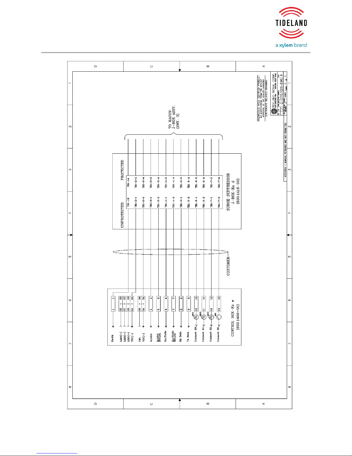
Wiring connections are made to Weidműeller part number 0294360000 feed through
terminals. Please see the manufacture’s data sheets for connection details and wire sizes.
Connections to the racon junction box are made via Pepperl+Fuchs DP-LBF-11.34 surge
protection devices. The maximum wire sizes are 2.5 mm2 or less than 10AWG.
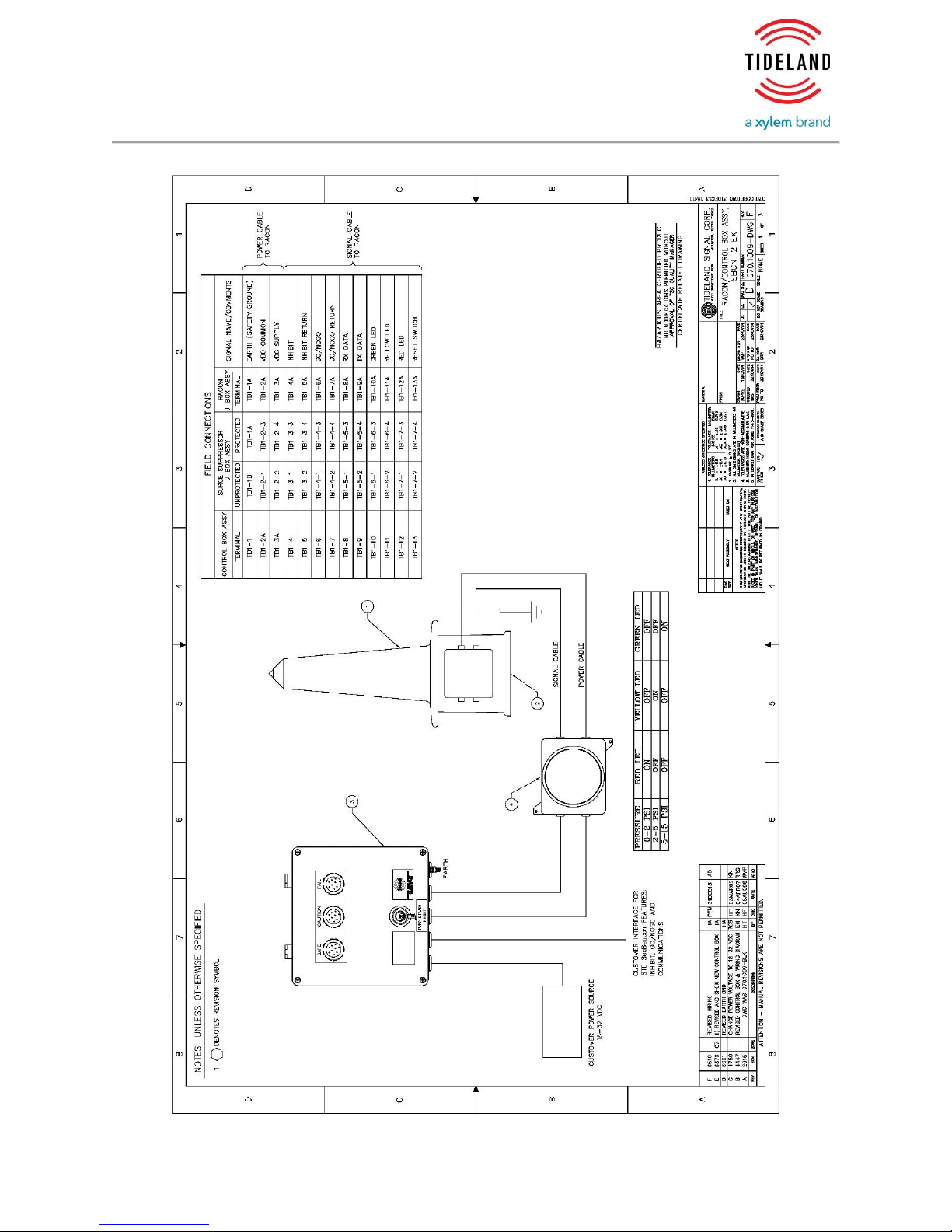
See drawing 0701009-DWG included with your racon. All “Customer Field Wiring” should
be as short as is practicable.
Power Source
Your racon is a 24 volt Direct Current (DC) device. The best power source is a battery with
some kind of charger. Electrical DC power supplies may be used but they must be able to
go from a few milliamps to 2 amperes in less than a few milliseconds. I.e. the power supply
must have very low internal impedance. Usually the simplest and most reliable solution is
a battery. The DC source should be located close to the control box and the wiring from
the control box to the racon should be kept very short.
Wire List:
Control
Box
Description
Surge Supressor J-Box
Unprotected
Protected
Racon J Box
1
Earth
TB1-1B
TB1-1A
TB1-1A
2A
24V Battery Minus (-)
TB1-2-1
TB1-2-3
TB1-2A
3A
24V Battery Plus (+)
TB1-2-2
TB1-2-4
TB1-3A
4
Inhibit or Blanking (+)
TB1-3-1
TB1-3-3
TB1-4A
5
Inhibit or Blanking (-)
TB1-3-2
TB1-3-4
TB1-5A
6
Go/No Go or Status (+)
TB1-4-1
TB1-4-3
TB1-6A
7
Go/No Go or Status (-)
TB1-4-2
TB1-4-4
TB1-7A
8
RS232C Rx data
TB1-5-1
TB1-5-3
TB1-8A
9
RS232C Tx data
TB1-5-2
TB1-5-4
TB1-9A
10
Green Indicator Light
TB1-6-1
TB1-6-3
TB1-10A
11
Yellow Indicator Light
TB1-6-2
TB1-6-4
TB1-11A
12
Red Indicator Light
TB1-7-1
TB1-7-3
TB1-12A
13
Reset
TB1-8-2
TB1-7-4
TB1-13A

INSTALLATION AND OPERATION MANUAL
SeaBeacon® 2 System 6 Racon EX
0111296-00
Tideland Signal Page 6 of 24
0111296-00 Rev. A 1-Nov-16
1.3.1 Initial Turn On of your Racon
When power is initially applied to the control box, the red LED indicator light will
come on. In this initial condition there is no power to the racon.
1. Insert, rotate the key clockwise and push in briefly. This action sends a
reset or temporary power to the racon.
a. If the internal pressure is greater than 2 PSI (14 kPa) but less than 5 PSI
(35 kPa) then the yellow LED light will come on and stay on.
b. If the internal pressure of the racon is greater than 5 PSI (35 kPa) then
the green LED light will come on.
c. If either of the yellow or the green lights are on then the racon will
function normally.
Note: The yellow light is a warning that the racon is leaking pressure
and may soon fail.
d. If the red LED light stays on then the internal pressure of the racon is
less than 2 PSI (14 kPa) or there is a wiring error or other failure and
the racon will not be allowed to be powered up.
2. If the green light is on then the racon is on and the protection circuits are
working.
3. Test your racon with local radars for Morse Code, Time ON and Time OFF,
range and area availability.
1.4 INHIBIT AND STATUS DISPLAY
1.4.1 Inhibiting Racon Response to Fixed Radar
Racon responses may interfere with fixed local radars that are on the platform.
Inhibiting can be used to eliminate an undesirable racon reply. To use this function
connect an inhibit control signal from the fixed local radar to the racon. The inhibit
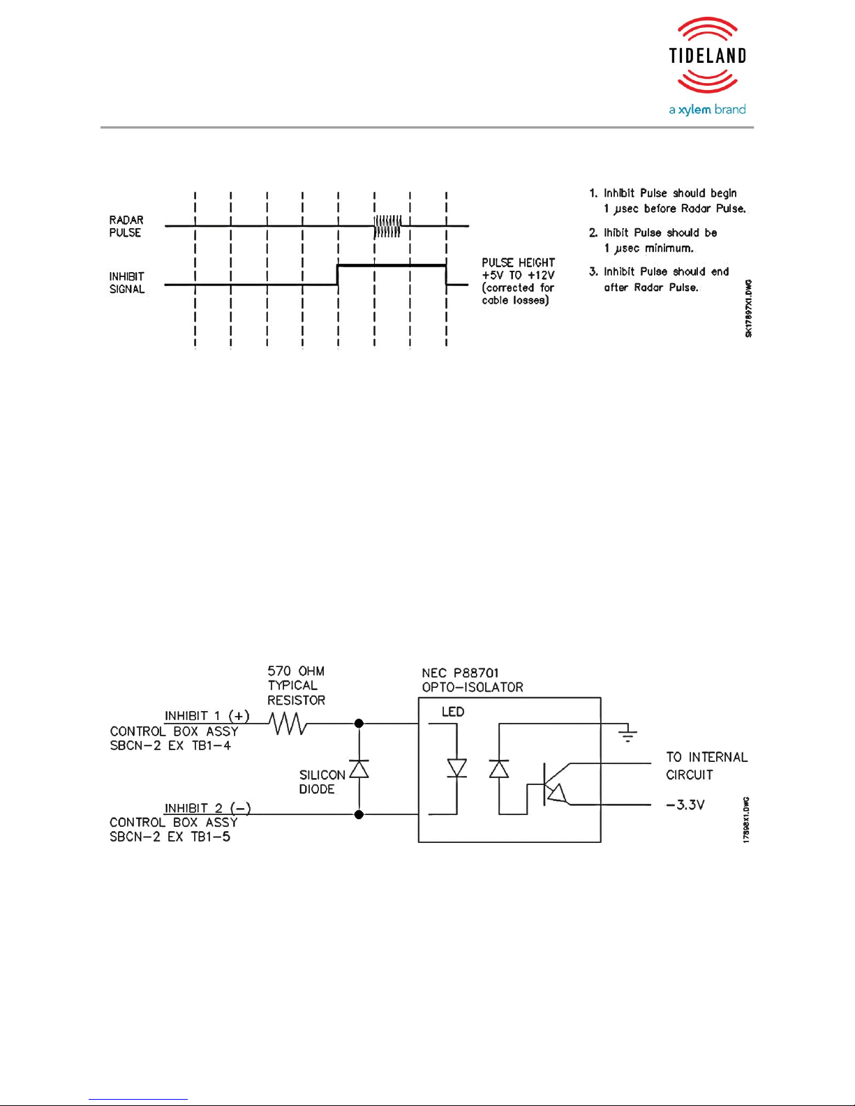
signal should have the characteristics shown in Figure 1.
INSTALLATION AND OPERATION MANUAL
SeaBeacon® 2 System 6 Racon EX
0111296-00
Tideland Signal Page 7 of 24
0111296-00 Rev. A 1-Nov-16
Figure 1. Inhibit Pulse Characteristics
The inhibit signal is driven from an external source of +5V to +12V pulses from a
local radar.
These signals are to be connected to the INHIBIT (+) with a return connected to
INHIBIT (-). The pulses should go active about one microsecond before the radar
begins transmission and remain till about one microsecond after the transmission
has ended. The input to the inhibit circuit is a NEC PS8701. The NEC PS8701 is an
optically coupled isolator containing a GaAIAs LED on the light emitting diode
(input) side and a PIN photodiode and a high speed amplifier transistor on the
output side. Typical ratings are VF = 1.7V at IF = 16mA (max), VF = 1.6V at IF = 1mA
for the LED. The LED has 520 ohms of external resistance in the anode circuit and
50 ohms in the cathode circuit for a total of 570 ohms of series resistance added
see Figure 2.
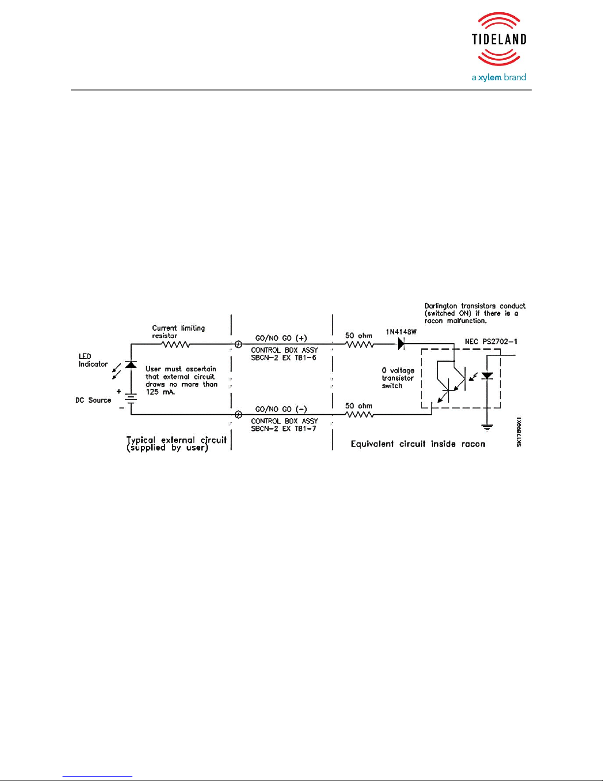
Figure 2: Functionally Equivalent Blanking Circuit Inside Room
1.4.2 Status Display
The status display lines (GO/NO GO + and -) provide a means of continuously
monitoring whether or not the racon has passed its self test. Figure B.3 shows a
functionally equivalent circuit along with a possible method for implementing the
INSTALLATION AND OPERATION MANUAL
SeaBeacon® 2 System 6 Racon EX
0111296-00
Tideland Signal Page 8 of 24
0111296-00 Rev. A 1-Nov-16
GO/NO GO function. The circuit can switch an outside current source of 125 mA
or less.
The polarity or signal sense that the SeaBeacon 2 System 6 EX racon provides, is
user selectable. The opto-isolator is normally turned on only if there is a racon
malfunction.
The output of the GO/NO GO circuit is a NEC PS2702-1 optically coupled isolator
containing a GaAs light emitting diode and an NPN silicon darlington-connected
phototransistor. There are two 50 ohm resistors, one on the GO/NO GO (+) and
the other on the GO/NO GO (-), and a 1N4148W diode in series on the GO/NO GO
(+) see Figure 3
Figure 3: The GO/NO GO Circuit
1.4.3 Purge and Pressure, General
Your racon was factory pressured and purged to 15 PSI (106 kPa) with dry
nitrogen. Nitrogen is used to reduce the aging effects of corrosion and oxidation.
While nitrogen is recommended it is not required to pressure your racon. Dry air
will work for the task; but it must be dry. Any moisture in the air will eventually
condense out onto the internal electronics and will significantly shorten the useful
life of the racon.
The purposes of the pressure are twofold:
1. First, pressuring is necessary to meet the permit requirements of this
hazardous area certified product.
2. Second, the internal pressure is an indicator of how well, or not, the racon is
sealed against the external marine and potentially explosive environment. The
internal electronics are extremely fragile and they are easily damaged beyond
reasonable repair efforts by moisture or by chemical contamination.

INSTALLATION AND OPERATION MANUAL
SeaBeacon® 2 System 6 Racon EX
0111296-00
Tideland Signal Page 9 of 24
0111296-00 Rev. A 1-Nov-16
Routine pressuring or purging is not required nor is it recommended. Routine
checks of the pressure are recommended at six month intervals and not longer
than one year. The pressure may be tested with an external low pressure gauge
or by communications with the racons’ internal pressure sensor. (See section 3.5
“User Functions” subsection “7 RACON MONITOR” in installation manual
0111181-00) Some loss of pressure can be expected over long periods of time.
Pressure losses that cause the yellow LED light to come on should be promptly
attended to.
1.4.4 Gather and Assemble Pure and Pressure Devices
Parts
1. Pressured Nitrogen source –usually a high pressure bottle
2. Low pressure regulator –Pressures in excess of 30 PSI (207 kPa) will cause
damage to your racon that will require extensive and costly repairs.
3. Pressure gauge - capable of displaying low pressures of 1PSI(7 kPa) to 15PSI
(103 kPa)
4. Interconnecting hose and adapters
1.4.5 Purging and Pressuring
Purge
1. Close the isolation valve.
2. Set the outlet pressure of the low pressure regulator to 20 to 25 PSI (138 to
172 kPa)
3. Remove the cap from the purge inlet valve. Set it aside for later. Install
adapters as needed.
4. Remove the tamper resistant vent valve at the top of the racon radome. The
vent tool, 2971010-00, or other appropriately sized rod will do. Save the flat
gasket.
5. Connect the pressure source hose to the racon.
6. Slowly open the isolation valve. Do not let the pressure climb above 15 PSI
(106 kPa).

INSTALLATION AND OPERATION MANUAL
SeaBeacon® 2 System 6 Racon EX
0111296-00
Tideland Signal Page 10 of 24
0111296-00 Rev. A 1-Nov-16
7. Let the gas flow through the racon and out the top valve for about 5 minutes.
8. Close the isolation valve.
9. Install the vent valve gasket and the vent valve. Tighten the valve with the
vent tool until the valve seats firmly on the radome. Excessive torque will
damage the radome bolt, 2111550-00 SCREW CONT RETAINING SBCN-2.
Pressuring
1. Slowly open the pressure isolation valve till the gauge reads 15 PSI (106kPa).
2. When the gauge reaches 15 PSI then close the isolation valve. The gauge
reading will drop.
3. Open the isolation valve again till 15 PSI is reached. Close the valve again.
4. Repeatedly open and close the isolation valve until the gauge reading holds at
15 PSI (106 kPa).
5. Close the isolation valve.
6. Turn off the gas to the low pressure regulator.
7. Quickly remove the hose from the racon purge inlet valve.
8. Firmly reinstall the purge inlet valve cap.
9. Your racon is now purged and pressured.
10. Test for leaks. This can be done with soapy water applied around all
connections. If bubbles are seen then the racon seals must be repaired. Please
contact your Tideland Signal Corp. representative for assistance.

INSTALLATION AND OPERATION MANUAL
SeaBeacon® 2 System 6 Racon EX
0111296-00
Tideland Signal Page 11 of 24
0111296-00 Rev. A 1-Nov-16

INSTALLATION AND OPERATION MANUAL
SeaBeacon® 2 System 6 Racon EX
0111296-00
Tideland Signal Page 12 of 24
0111296-00 Rev. A 1-Nov-16

INSTALLATION AND OPERATION MANUAL
SeaBeacon® 2 System 6 Racon EX
0111296-00
Tideland Signal Page 13 of 24
0111296-00 Rev. A 1-Nov-16

INSTALLATION AND OPERATION MANUAL
SeaBeacon® 2 System 6 Racon EX
0111296-00
Tideland Signal Page 14 of 24
0111296-00 Rev. A 1-Nov-16

INSTALLATION AND OPERATION MANUAL
SeaBeacon® 2 System 6 Racon EX
0111296-00
Tideland Signal Page 15 of 24
0111296-00 Rev. A 1-Nov-16
INSTALLATION AND OPERATION MANUAL
SeaBeacon® 2 System 6 Racon EX
0111296-00
Tideland Signal Page 16 of 24
0111296-00 Rev. A 1-Nov-16
INSTALLATION AND OPERATION MANUAL
SeaBeacon® 2 System 6 Racon EX
0111296-00
Tideland Signal Page 17 of 24
0111296-00 Rev. A 1-Nov-16
Table of contents
Popular Boating Equipment manuals by other brands

Scanstrut
Scanstrut Scanpod SPR-1i-AM installation instructions

Nielsen-Kellerman
Nielsen-Kellerman SpeedCoach XL1 Troubleshooting

Vetus
Vetus BOW1254DE Operation manual and installation instructions

MINN KOTA
MINN KOTA i-Pilot Link Quick reference guide

Floe
Floe 510-27100-00 Assembly instructions and owner's manual

Easytow
Easytow ski owner's manual

Floe
Floe VSD 5000 Assembly instructions

Sleipner
Sleipner SX35POD installation guide

JOBE
JOBE TOWER BIMINI installation guide

South Pacific Industrial
South Pacific Industrial DW700 Owner's installation & operations manual

Boston Whaler
Boston Whaler Pilot Seat Assembly instructions

Harken
Harken 418 instructions


