Tie Down Engineering Roof Zone Penetrator 2+2 User manual
TMTM
TIE DOWN ENGINEERING • Atlanta, GA 30336
www.tiedown.com (404) 344-0000
Serious injury or death may occur if this equipment is used for purposes other than intended.
Tie Down Engineering provides the following instructions for the use and care of this
equipment. It is the responsibility of the user to understand and convey proper instruction to
any and all individuals who use this product for Fall Arrest and or Fall Restraint. The
Penetrator 2+2 complies with the requirements set forth by the Federal Occupational Safety
and Health Administration (OSHA) when used according to the manufacturers’ instructions.
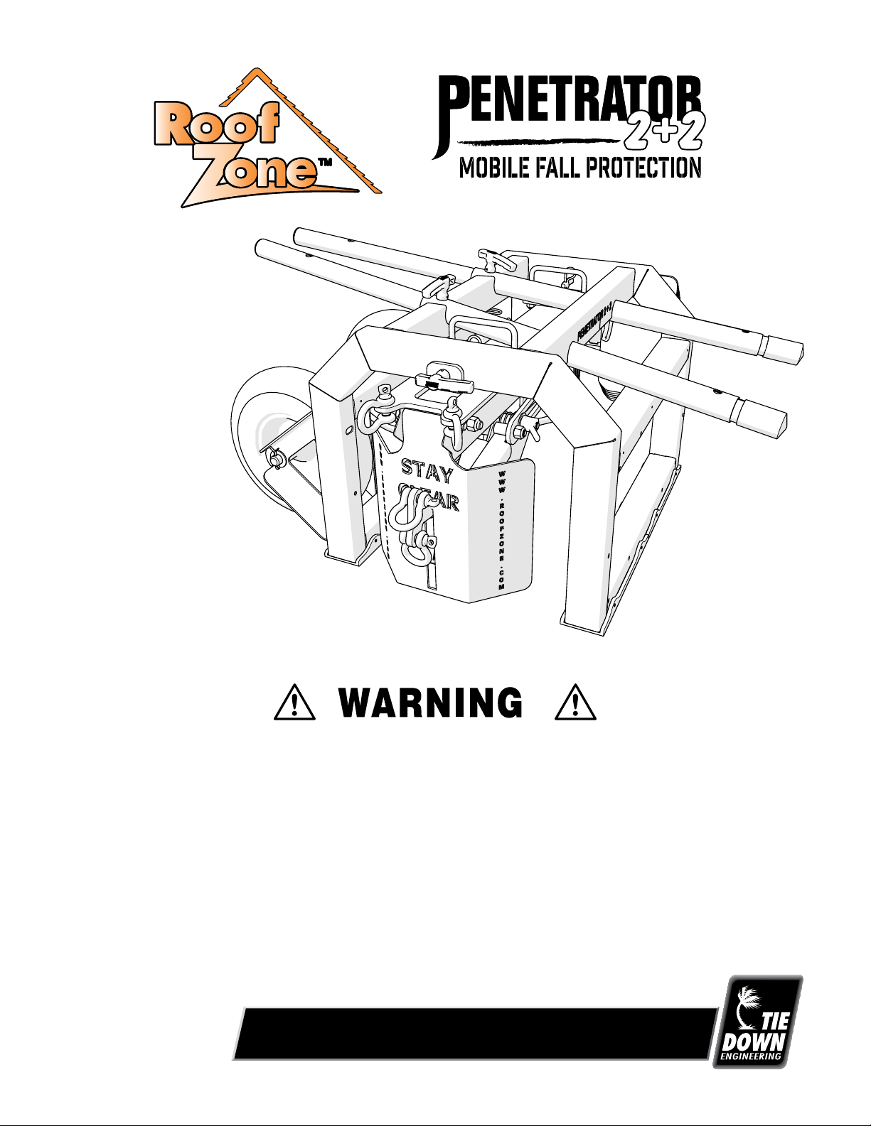
Penetrator 2+2 Fall
Protection Device
Model #40640
Instruction Sheet
#08282 Rev. 4/11/17
Page 1 of 12
E1509; 041117
TMTM
TIE DOWN ENGINEERING • Atlanta, GA 30336
www.tiedown.com (404) 344-0000
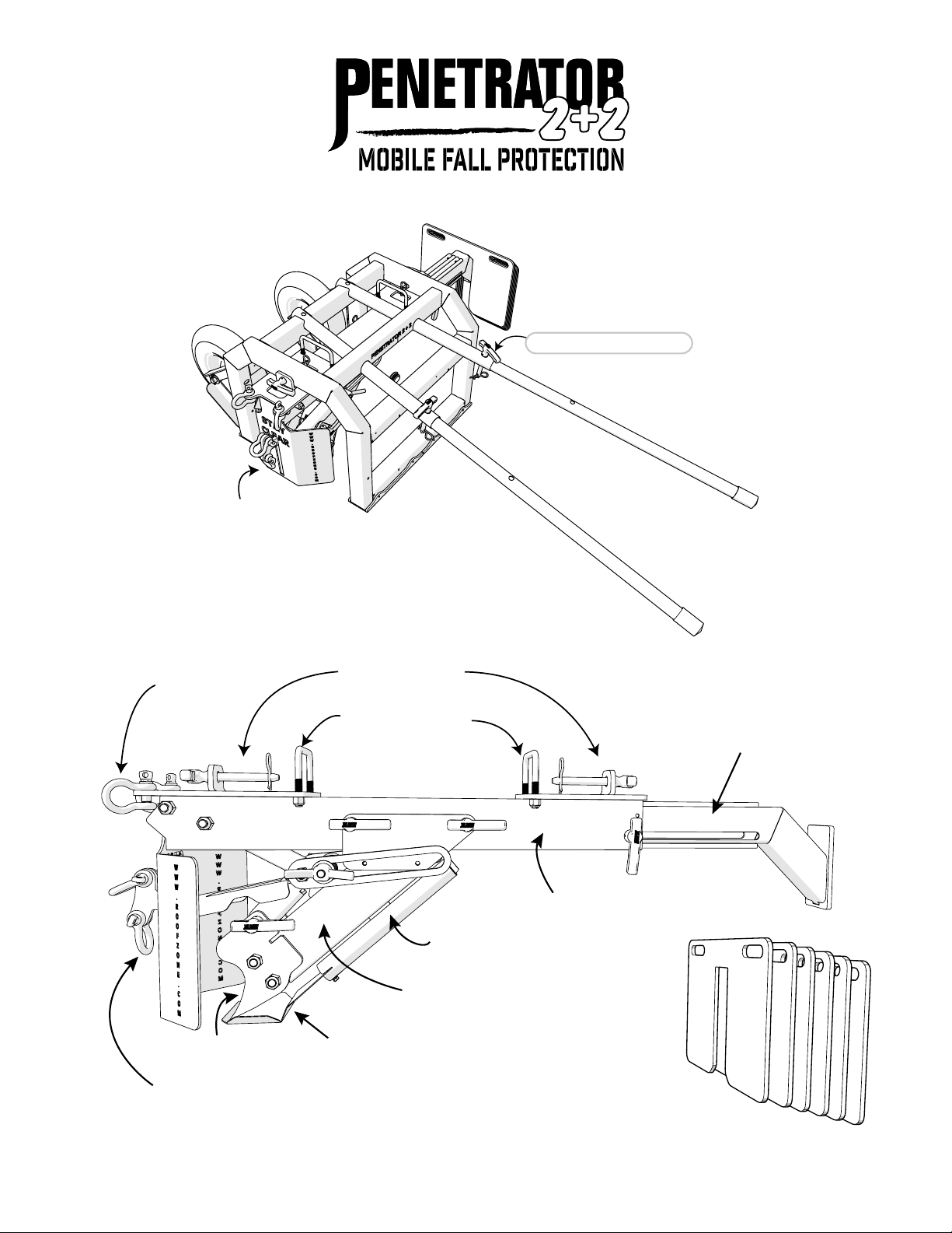
Handles -
Fully Extended
Includes: 6 - 25 lbs. Each
Ballast Slide
Instruction Manual Tube
Spike
Guard Shield
Mounting Pins
Lifting Handles
Fall Restraint
Connection
“FRS”
Personal Fall Arrest
Connection
“PFAS”
Mounting Frame
Penetrator 2+2 Fall
Protection Device
Spike Engagement Tube
Ballast Weights
Penetrator
Spike
Handle Locking Pin
2

When set up properly the Penetrator 2+2 allows for two workers to be tied off for fall arrest using the specially
designed fall arrest connection mechanism with two individual attachment points. An additional two workers
can be tied-off for fall restraint at the specified attachment points.
Fall Restraint System – A fall restraint system (FRS) prevents the user from falling. The system is comprised of
a body harness along with an anchorage, connectors and other equipment. The components typically include a
lanyard and also may include a lifeline and other devices. The Penetrator 2+2 can be used as an anchorage in a
fall restraint system for up to two workers.
Personal Fall Arrest System – A personal fall arrest system (PFAS) arrests a fall after a fall incident has
occurred. The system is comprised of an anchor point, connecting device, body harness, connectors, and a body
harness and must include a deceleration system, or suitable combinations. Note that a PFAS does NOT prevent a
fall from occurring. The Penetrator 2+2 can be used as an anchorage in a PFAS for up to two workers. A Person-
al Fall Arrest System must meet the following OSHA requirements:
• Limit maximum arresting force on an employee to 1,800 pounds when used with a body harness;
• Be rigged (lifeline plus deceleration device) so that an employee can neither free-fall more than 6 feet
(1.8 meters) nor contact any lower level;
• Bring an employee to a complete stop and limit maximum deceleration distance an employee travels
to OSHA 3.5 feet (1.07 meters); and 4 ft. per ANSI 359.
• Have sufficient strength to withstand twice the potential impact energy of an employee free-falling a
distance of 6 feet (1.8 meters) or the free-fall distance permitted by the system, whichever is less.
Anchorage — An anchorage is a secure point of attachment for lifelines, lanyards, or deceleration devices. The
Penetrator 2+2 is a mobile anchorage.
Penetrator 2+2 Use - For use on flat surfaces only.
Applications
3

Recommended Surfaces:
✔Gypsum Deck
✔Modified Bitumen Membranes
✔Built-up Roofing (BUR) Membrane
✔Modified PVC Membranes
✔Thermoplastic Polyolefin (TPO) Membranes
✔Polyisocyanurate (ISO)
✔Expanded Polystyrene (EPS)
✔EPDM Roofing Membranes
✔Ballasted EPDM Membrane
✔Hardboard
✔Flat Surfaces to slopes up to 1:12.
✔Metal Deck (20 ga. and 22 ga. ONLY)
✔Dens Deck
✔Plywood
Do Not Use on the Following Surfaces:
✖ Metal Deck less than 22 ga.
Or over 20 ga. (Structural Deck)
✖ Loose laid material not part of a complete
finished system.
✖ Ice
✖ Snow
✖ Tectum Deck
✖ Concrete
Applications: Surfaces
Roofing Load Requirements
Before the Penetrator 2+2 and cart are hoisted to any roofing deck the user MUST VERIFY
THAT THE DECK CAN ACCOMMODATE THE LOAD REQUIREMENTS.
Verify that the surface that the Penetrator 2+2 will be used on is capable of supporting both the unit and
personnel using it. Inspect that the entire area to determine if the working surfaces have the strength
and to support users safely.
CAPACITY: The Penetrator 2+2 Mobile Fall Protection System is designed for a maximum of two persons
for fall arrest and two for fall restraint with a combined weight (clothing, tools) of no more than
310 lbs. per person. No more than four persons may be connected to the Penetrator 2+2 at any time.
IMPORTANT: DO NOT start work for which fall protection is required until the Penetrator 2+2 and
corresponding FRS or PFAS have been completely installed. Do NOT disable any part of the FRS or
PFAS, including the Penetrator 2+2 unit, or reposition the unit, until work for which fall protection is
required has ceased.
4
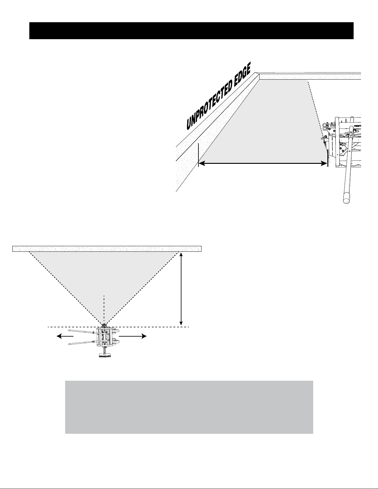
Placement/Repositioning of the Penetrator 2+2
The attachment tie-off anchor shackles must
be pointed toward the leading edge and the
cart is set to travel parallel to the unprotected
edge or leading edge.
Position the Penetrator 2+2 such that
the front guard plate is between 4 to 15 feet
from the leading edge, and in line with the
center of the area to be worked.
SAFE WORK ZONE
Minimum
4 ft. from
Unprotected Edge
4 ft. to 15 ft.
Cart
Path
Maximum
15 ft. from
Unprotected Edge
SAFE WORK
ZONE
4 ft. to
15 ft.
Unprotected Edge or Leading Edge
45˚ 45˚
RANGE OF USE
SAFE WORK ZONE
Minimum
4 ft. from
Unprotected Edge
4 ft. to 15 ft.
Cart
Path
Maximum
15 ft. from
Unprotected Edge
SAFE WORK
ZONE
4 ft. to
15 ft.
Unprotected Edge or Leading Edge
45˚ 45˚
RANGE OF USE
5
IMPORTANT: DO NOT allow workers to cross paths (cross lines) at anytime!
Fall Restraint/Fall Arrest lines must never cross over each other. Crossed
lines will cause the unit to not function as intended. Failure to maintain
clear lines may cause a accident or death.
Prior to Positioning the Penetrator 2+2:
Verify that the surface is capable of supporting the
Penetrator 2+2, ballast weights, cart, and
all personnel using it.
During Repositioning the Penetrator 2+2:
Active fall restraint is maintained by a maximum
length of five feet less than the distance of the cart
to the leading edge.
IMPORTANT: When repositioning the
Penetrator 2+2, active fall restraint is
maintained by a maximum length of five
feet less than the distance of the cart
to the leading edge.
Ballast Slide
Ballast Slide
Pull Pin
Ballast Slide
Ballast Slide
Pull Pin
Ballast Slide
Ballast Slide
Pull Pin
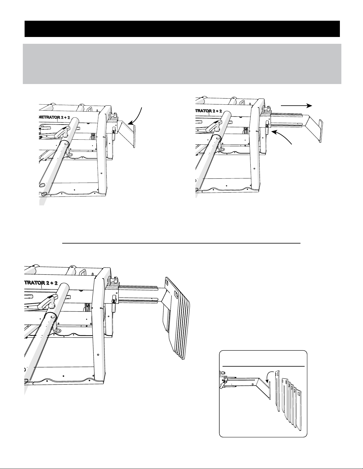
Setting the Ballast Slide and Weights
DO NOT use the Penetrator 2+2 Roofing Cart without the ballast slide extended and all ballast weights applied.
Once the location for the operation of the Penetrator 2+2 has been determined, the ballast slide must be
adjusted to the proper operational length.
Step 1
Pull the ballest slide out until it stops.
DO NOT REMOVE THE BALLAST PULL PIN
Step 2
Carefully place the ballast weights one at a time.
Be carefully when placing the ballast, each weight
has the potential of being a pinch point.
DO NOT USE THE PENETRATOR 2+2 WITHOUT
THE BALLAST SLIDE ARM EXTENDED AND
THE BALLAST WEIGHTS APPLIED.
6
ATTENTION!
Ballast Slide Must
Be Fully Extended!
ALL 6 Ballast Must Be
Applied on the Ballast Slide!
#15796

Connecting to the Penetrator 2+2
Before Using the Penetrator 2+2
DO NOT hook Personal Fall Arrest System (PFAS) to any point except a Fall Arrest or Fall Restraint Tie-off
Anchor Shackle.
When making connections, only use double-locking snap hooks and double-locking carabiners with this equipment.
Only use connectors that are suitable to each application. Ensure all connections are compatible in size, shape
and strength. Do not use equipment that is not compatible. Ensure that all connectors are fully closed and locked.
The Fall Restraint Tie-Off Shackles
Two Fall Restraint Anchor Shackles are installed on
the top side of the Penetrator 2+2 where labeled.
The Fall Restraint Anchor Shackles DO NOT
arrest falls . The user must insure that the Fall
Restraint worker is personally equipped with
lanyards, harnesses, safety lines, etc., when
working in conjunction with potential
fall arrest workers.
Do Not allow the fall restraint user to work
close to any roof edge.
FALL ARREST TIE-OFF Shackles
The two Fall Arrest Tie Off shackles are located on the
lower side of the Penetrator 2+2, in front of the stay
clear guard as labeled. The user must insure that the
lanyards and harness are properly attached.
Fall Restraint Anchor Shackles
Fall Arrest Anchor Shackles (2)
OSHA requires that before operating the system there must be an inspection for damaged equipment.
1 Check for loose, bent or damaged parts, including the three penetrating spikes.
2 Check welded components for distortion, cracks, or other damage.
3 Check Tie-off shackles for distortion or damage and confirm that they are properly tightened.
4 Check retaining slide bars for rusting and/or wear before each use.
5 All labels must be present and fully legible. (Copies of all labels are attached at the back of this
section for accurate inspection.)
6 Check for all pull pins that they are fully inserted and the safety cotter pin clips are
attached to each pull pin.
IMPORTANT: Confirm all screw pins on all four anchor shackles are fully inserted prior to attachment
of Fall Restraint or Fall Arrest lines.
IMPORTANT: DO NOT allow workers to cross paths (cross lines) at anytime! Fall Restraint/Fall Arrest
lines must never cross over each other. Crossed lines will cause the unit to not function as intended.
Failure to maintain clear lines may cause a accident or death.
7

Maintenance and Care
General Safety Precautions
IMPORTANT: BEFORE USING THIS UNIT, A RESCUE PLAN MUST BE ADOPTED.
OSHA requires employers to provide a quick rescue of employees in the event of a fall or employers
shall assure that employees are able to rescue themselves. It is impossible to guarantee that an
employee can rescue himself because he may be unconscious or injured as a cause or result of the
fall. Therefore, a procedure involving rescuers must be adopted.
Consult with your roofing distributor/supplier for fall rescue equipment.
USE COMMON SENSE! Most accidents can be avoided by using common sense and concentrating on the job at
hand. Look around and confirm a safe distance from the roof edge is being maintained.
The Penetrator 2+2 should not be used by persons whose ability or alertness is impaired by fatigue, intoxicating
beverages, illegal or prescription drugs, or any other physical cause that exposes the user or others to injury.
Always wear proper safety attire.
Keep hands and feet clear of moving parts. DO NOT stick hands or fingers in the equipment when workers are
attached to the Penetrator 2+2.
Do not operate the equipment near electrical power lines. ELECTRICITY KILLS!
DO NOT OPERATE DAMAGED EQUIPMENT. DO NOT OPERATE EQUIPMENT THAT HAS BEEN MODIFIED.
(Please use the Inspection and Maintenance Log contained within the instructions manual )
✔Inspect Penetrator 2+2 before and after each use.
✔Keep wheels free from roofing debris.
✔Regularly inspect for damaged or missing parts and do not place the Penetrator 2+2 into service until
all missing and or damaged parts have been replaced.
✔Store the Penetrator 2+2 in a place protected from weather and where only authorized employees
have access. Optional Penetrator 2+2 all weather protective cover may be purchased separately.
✔Maintain finish to prevent corrosion.
8

General Safety Precautions
Hoisting Safety Precautions
Procedure for Handling the Penetrator 2+2 After a Fall
Ensure that all areas directly underneath, and in front of the cart, are clear and free of debris.
Do not use on roofs with ice or snow.
Only use the unit on a surface or roof composition for which it has been tested.
Do not set unit atop unfastened materials. Materials may slide if not mechanically attached to the roof.
Loads may slip, if the Penetrator 2+2 is not hoisted properly, this could result in injury or death.
Do not use with damaged slings or chains.
Utilize appropriate rigging gear for overhead lifting.
Utilize rigging gear within the industry standards and the manufacturer’s recommendations.
Conduct regular inspection and maintenance of the rigging gear.
DO NOT hook to the fall arrest or fall restrain shackle safety line connectors when lifting the cart.
Before rescuing a fallen employee, check that the Penetrator 2+2 is secure.
It is highly recommended that any rescuer be tied off in a FRS before attempting to aid in a rescue.
The number of rescuers allowed to tie off to the Penetrator 2+2 is 2 (two) minus the number of fallen
workers. Up to 2 (two) additional rescuers may tie off to the Penetrator 2+2 utilizing the two fall restraint
tie-off shackles marked for FRS.
Prior to disengaging the Penetrator 2+2 after deployment as the result of an fall incident, make certain
that the rescue procedure has been successfully completed.
9
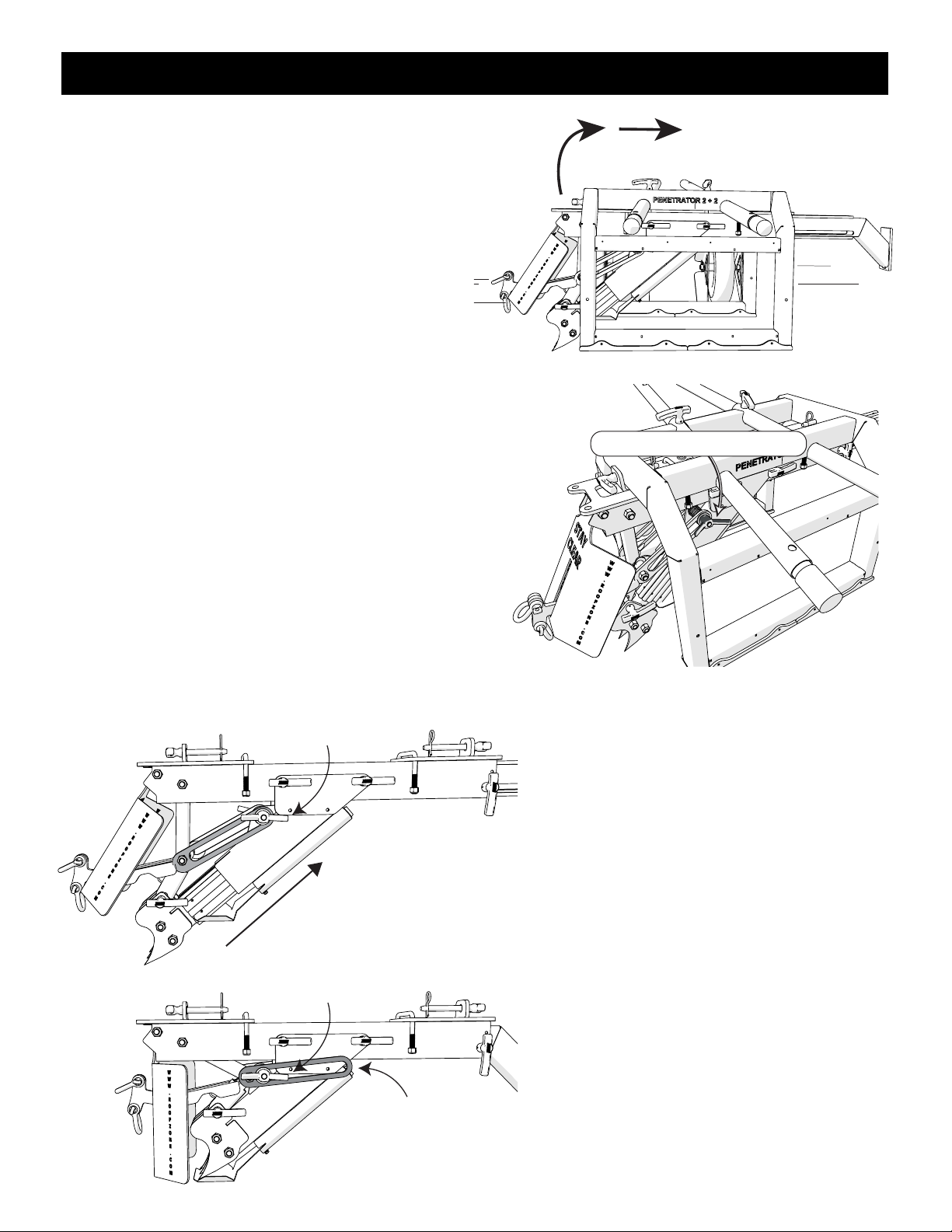
Procedure for Reseting the Penetrator 2+2 After a Fall
Rotate and Pull Back
Wing Nut - On Each Side
Loosen Wing Nut
OK to Tighten Wing Nut
Retaining Slide
Bar
Prior to disengaging the Penetrator 2+2 after
deployment as the result of an fall incident, make
certain that the rescue procedure has been
successfully completed.
The three penetrating spikes will be somewhat buried
into the roof after activation.
Follow these steps to reset the Penetrator 2+2 Device:
1. Remove the ballast weights.
2. Using at least two people, rotate the entire cart
while sliding it backward from the engagement
point. Once the spikes are clear of the engagement
area, it is safe to slowly lower the roofing cart.
3. Loosen the Wing Nuts on each side of the Spike
engagement tube.
4. Standing behind the Penetrator 2+2, reach down
through the cart, and grasp the upper front
sides of the outer spikes. Pull upward on the inner
spike tube, as you pull up the front guard
plate and other components will reset to their
original positions.
Rotate and Pull Back
Wing Nut - On Each Side
Loosen Wing Nut
OK to Tighten Wing Nut
Retaining Slide
Bar
Rotate and Pull Back
Wing Nut - On Each Side
Loosen Wing Nut
OK to Tighten Wing Nut
Retaining Slide
Bar
5. Continue pulling up the inner spike tube
until it stops. When the inner spike tube is
fully inserted into the outer engagement
tube, firmly tension the two large wing nuts
on both retaining slide bars until fully seated
against the threaded slide bolt.
(See illustration on the left).
Always use caution when disengaging the outer
engagement tube as well as reinserting the inner
engagement tube as these areas can become
pinch points and cause bodily injury.
Do not reuse the Penetrator 2+2 after incident
until fully inspected and any damaged parts
have been replaced and recertification and
inspection has been performed.
See inspection check list on back cover.
10

Warning and Product ID Labels
Product Model ID
& Serial Number
11

Inspection Checklist
and Maintenance Log
Penetrator 2+2 Model #_____________________ Date of Purchase: __________________
Serial Number: ________________________ Purchased From: ______________________
Cart
Frame: Free of Rust?
Frame: Welded Connections?
Axles/Wheels Rotate Properly?
Overall Cart Parts?
Date Corrective Action Taken:
Penetrator 2+2 Device
Frame: Free of Rust?
Frame: Welded Connections?
Mounting Pins (2)?
Ballast Slide: Slides In and Out?
Ballast Slide: Pin Available?
Penetrator 2+2 Spikes Free of Damage?
All Ballast Weights Available (6)?
Spike Guard Shield Present?
Anchor Shackles and Pins Available (4)?
Anchor Shackles and Pins Tightened?
Retaining Slide Bar Clear of Any Obstructions?
Wing Nut Tightened/Retaining Slide Bar?
Inner/Outer Spike Tube Engaged?
(If “Yes” DO NOT USE)
Pull Pins (5) Secured with Safety Cotter Pin?
Safety and Warning Labels Readable?
Date:
Date:
TMTM
12
This manual suits for next models
1
Popular Protection Device manuals by other brands

ABB
ABB Relion 670 series Commissioning manual

SENTRY GUARDING SYSTEM
SENTRY GUARDING SYSTEM 600 GUARDING installation manual

GE
GE D30 series instruction manual

Cedes
Cedes cegard/Lift LX/LY Installation and operation manual

Phyn
Phyn Plus Installer's guide

Schweitzer Engineering Laboratories
Schweitzer Engineering Laboratories SEL-311C instruction manual


