Cedes cegard/Lift LX/LY User manual

RoHS
Installation and Operation Manual
100 953 | 220503 | V 2.10
English Pages 2 – 26 Original version
German Seiten 27 – 51
CEDES AG is certified according to ISO 9001: 2015
cegard/Lift LX/LY

cegard/Lift LX/LY English
2 © CEDES | V 2.10
1. About this manual
This installation and operation manual, with metric
measurements is the original version.
The version number is printed at the bottom of each page.
To make sure you have the latest version, visit www.cedes.
com where this manual and related documents can be
downloaded.
1.1 Measurements
Measurements are, if not stated otherwise, given in mm
(non-bracketed numbers) and inches (numbers in brackets).
1.2 Related documents
cegard/Lift LX, LY datasheet en
Part No. 001 010 en
cegard/Lift LX, LY (70 beams) datasheet en
Part No. 001 128 en
1.3 CEDES headquarter
CEDES AG
Science Park
CH-7302 Landquart
Switzerland
CEDES AG reserves the right to modify or change technical data without prior notice.
Contents
1. About this manual 2
1.1 Measurements 2
1.2 Related documents 2
1.3 CEDES headquarter 2
2. Safety information 3
2.1 Non-intended use 3
3. Symbols, safety messages 3
3.1 Safety messages categories 3
4. Indroduction 4
5. Description of function 4
5.1 Structure 4
5.2 Interface to elevator controller 4
5.3 Timing diagrams 7
5.4 Description of light curtain component 9
6. Installation 9
6.1 Installation of opto edges 9
6.2 Installation system control rack 10
6.3 Flush mounting kit 10
6.4 Surface mounting kit 10
7. Connection configuration 11
7.1 cegard/Lift LX with latch contactor 12
7.2 cegard/Lift LY with latch voltage rectifier 12
8. Switching examples 13
8.1 Connecting a single-phase latch solenoid 13
8.2 Connecting a three-phase latch solenoid 13
8.3 Connecting two external output contactors
to safety circuit 13
8.4 Overriding the light curtain 13
8.5 Avoidance of errors 14
8.6 Latch-stopping time following the ending of
emergency stop via Reset 14
8.7 Example 1 with cegard/Lift LX: Light curtain with
dropped-out (released) latch solenoid actuation 15
8.8 Example 2 with cegard/Lift LX: Bypassed light
curtain in floor zone 16
8.9 Example 1 with cegard/Lift LY: Bypassed light
curtain with dropped-out (released) latch
solenoid actuation 17
8.10 Example 2 with cegard/Lift LY: Bypassed light
curtain in the zone 18
9. Commissioning 19
9.1 General description 19
9.2 Installation check 19
9.3 Function test 19
10. Display and operating elements 20
10.1 Tumbler switch on control unit plug-in 20
10.2 Tumbler switch on plug-in system
controller (Service button) 20
10.3 “Status” output on control unit plug-in (Loading
or door control) 20
10.4 Display elements 21
10.5 Display and operation in cabin interior 21
11. Error diagnosis 22
11.1 Plug-in system controller, interface for elevator
control 22
11.2 Control unit plug-in with optical edges 22
12. Regulations 23
12.1 Legislation and regulations 23
12.2 Qualifications of skilled personnel 23
12.3 Periodic testing 23
12.4 Reflection 23
12.5 Cleaning the opto edges 23
13. Decommissioning, repair and disposal 23
13.1 Decommissioning 23
13.2 Repair 23
13.3 Disposal 23
14. Technical data 24
15. Order information 25
15.1 System components 25
15.2 Replacement / Individual parts 26
15.3 Accessories 26
15.4 Customer specific opto edge pairs 26
16. Dimensions 51
16.1 System control rack housing 51
16.2 Opto edges / Lift LX,LY
(Part No. 101 072 & 101 073) 52

cegard/Lift LX/LY English
© CEDES | V 2.10 3
2. Safety information
The light curtain should never be installed in the elevator
control in a manner which allows the doors to be opened
during an emergency stop caused by an interruption of
the protective field in the unlocking zone. This results
in a dangerous step. Please read the instructions in
Chapter 5.2.7.
If a person leaves the elevator car at this holding position
without pressing the desired landing floor button again,
with hydraulically driven elevators, there is still the danger
that the elevator can slowly fall away from the holding
position due to leakage of the elevator’s hydraulic system.
The next elevator user could fall into the cabin or the
elevator shaft after the landing doors are opened.
This risk does not arise if the cegard/Lift is connected
correctly.
Please check your installation in accordance with the
specified criteria in Chapter 11.
The cegard/Lift LX/LY was developed and manufactured
using state-of-the-art systems and technologies. However,
injury and/or damage to the sensor can still occur.
To ensure safe conditions:
Read all enclosed instructions and information and
make sure you have understood it.
Follow the instructions given in this manual carefully.
Observe all warnings included in the documentation
and attached to the sensor.
Do not use the sensor if it is damaged in any way.
Keep the instruction manual on site.
It is the sole responsibility of the planner and/or installer
and/or buyer to ensure that this product is used according
to all applicable local standards, laws and regulations in
order to ensure safe operation of the whole application.
Only personnel authorized and instructed by the system
integrator are allowed to operate, install and maintain the
cegard/Lift LX/LY.
Any alterations to the system by anyone (e.g. the buyer,
installer or user) may result in unsafe operating conditions.
CEDES is not responsible for any liability or warranty claim
that results from such manipulation. Failure to follow
instructions given in this manual and/or other documents
related to the cegard/Lift LX/LY may cause customer
complaints, serious call backs, damage, injury or death.
2.1 Non-intended use
The cegard/Lift LX/LY must not be used for:
• Protection of dangerous machine
• Equipment in explosive atmospheres
• Equipment in radioactive environments
Use only specific and approved safety devices for such
applications, otherwise serious injury or death or damage
to property may occur! A CEDES safety light curtain for
explosion hazardous areas (ATEX) is available.
3. Symbols, safety messages
3.1 Safety messages categories
Warning of serious health risks
WARNING
Serious health risks
Highlights critical information for the safe use
of the sensor. Disregarding these warnings
can result in serious injury or death.
Follow the measures highlighted by the
triangle-shaped arrows
Consult the safety information in Chapter
2 of this manual
Caution of possible health risk
CAUTION
Possible health risks
Highlights critical information for the safe use
of the sensor. Disregarding these warnings
can result in injury.
Follow the measures highlighted by the
triangle-shaped arrows
Consult the safety information in Chapter
2 of this manual
Symbol Meaning
Single instruction or measures in no
particular order
1.
2.
3.
Sequenced instructions
• List, in no order of importance
àReference to a chapter, illustration or
table within this document
Important Important information for the correct use
of the sensor
IMPORTANT
READ BEFORE INSTALLATION!

cegard/Lift LX/LY English
4 © CEDES | V 2.10
Notice of damage risk
NOTICE
Risk of damage
Disregarding these notices can lead to damage
to the sensor, the door controller and/or other
devices.
Follow the measures highlighted by the
triangle-shaped arrows
4. Indroduction
The cegard/Lift light curtain serves to protect people
in cargo and passenger elevators without elevator cage
closure doors. The speed at which the elevator cage travels
should not exceed 0.85 m/s (max. 0.63 m/s in Switzerland
and Austria). All valid national regulations should be
observed.
IMPORTANT NOTICE
cegard/Lift is constructed exclusively for elevators,
and should not be used in areas where there is a
risk of explosion (ATEX-areas). However, a product
specifically designed for use in such ATEX-areas
(Zone 2 and 22) is also available.
The cegard/Lift carries out a self-test:
• Before each journey
• Every time a person or object interrupts the light
curtain
Every malfunction involving the opto edges, system control
rack or incorrect wiring leads to a shutdown of the elevator
system.
If an object causes an emergency stop by penetrating the
protective field during the journey, it can be signalled either
audibly or visually.
A journey interrupted by the safety equipment can only be
continued after the protective zone is reenabled by a new
drive / journey command from the interior of the elevator
cage.
Where an elevator has entrances on either side, both
are simultaneously bypassed. This occurs regardless of
whether there are one or two entrances to the elevator
cabin on a floor.
The cegard/Lift offers the following advantages:
• Also ideal for controlling automatic doors thanks to an
additional output
• Cost effective
• Simple integration into almost all existing elevator
control systems without additional travelling cables
• Simple, space-saving installation
• No setting or optical adjustment of the light curtain
necessary
• Short installation time, can be easily carried out by just
one single person
• Monitoring of up to two elevator cabin entrances
• Large range and dense protective field
• Automatic start after power-up
• 8 isolated inputs for cabin call signals,
12 … 265 VAC/DC
• Safety logics for the prevention of dangerous steps
into the elevator
• System control rack IP54
• Opto-edge IP65; IP67 optional (fully potted)
• Actuation for load control display available as
accessory
Assembly sets can be supplied as accessories which
enable integration, installation and commissioning by a
single installation fitter. The assembly kits also offer optimal
protection from daily industrial use.
5. Description of function
5.1 Structure
The cegard/Lift control unit is mounted on the elevator
car’s roof using the enclosed mounting rails.
The block circuit diagram (Figure 1) shows the setup.
Interface to the
elevator controller
Plug-in
system
controller
Control unit
Plug-in 1
Control unit
Plug-in 2
Light curtain
Entrance 1
Light curtain
Entrance 2
System control rack
Figure 1: Interface to elevator controller
5.2 Interface to elevator controller
The following signals from the elevator controller are
required for actuation:
• At least one internal call and/or reset signal from
inside the elevator cabin (Chapter 5.2.1)
• Latch power supply: Latch_In (Riegel_In) (Chapter
5.2.2)
• Supply voltage of 230 VAC must be permanently
supplied (Chapter 7.1)
Additional signals increase the elevator’s level of
comfort:
• Elevator shaft information (e.g. slower travel speed,
zone signal) for early bypassing of the system (Chapter
5.2.3)
• Signal for testing of the safety components of
cegard/Lift (Chapter 5.2.4)

cegard/Lift LX/LY English
© CEDES | V 2.10 5
The function of interface signals is described in detail in the
following chapters.
The plug-in system controller monitors the correct function
of interface signals. The elevator is immediately shut down
if an error is detected and an appropriate error message
appears on the diagnosis display.
The polarity at connections is irrelevant when actuating
internal call signals with AC voltage. Correct polarity should
be ensured for all other signals (see also Chapter 6.2.
and 7).
5.2.1 Internal call signal / Reset signal
- See also Chapter 7: K7K15
If an emergency stop is caused by the interruption of the
light curtain, an His displayed. The elevator can only be
released from this emergency stop state by the pressing
of a reset button from within the elevator car itself. There
are eight independent reset inputs for this purpose. The
journey can be continued if, with a free protection field, at
least one of the inputs receives a negative or positive pulse
(i.e. a reset button, for example, can be allocated to one of
the internal call signals).
A call signal (and consequently, a test) during a journey
does not adversely affect the function (i.e. safety contacts
do not drop out (double or multiple start).
Special operating mode:
The service button on the plug-in system controller provides
the elevator fitter with the possibility to simulate an internal
call signal during commissioning and inspection (after an
emergency stop). This enables the safety contacts to be re-
closed from the elevator cabin roof.
5.2.2 Latch power supply (Latch_In (Riegel_
In))
- See also Chapter 7: K24K25
The latch power supply is used to enable transit and to
unlock the door.
The bypassing of the light curtain is cancelled by the
Latch_In latch power supply HIGH signal, the Latch_Out
output is switched through and the door is locked as a
result. An Fis displayed and every interruption of the light
curtain now results in an emergency stop.
The latch circuit is described in Chapter 8.
5.2.3 Override delay and Option 2 (premature
overriding)
- See also Chapter 7: K18K19 / K22K23
The light curtain can be bypassed with the Override delay
(bypass delay) and Option 2 inputs. An Uis displayed.
Bypassing can begin before the Latch signal switches to
LOW. The light curtain is then overridden if both inputs are
LOW:
Override delay Option 2 Light curtain
overriding
HIGH HIGH Inactive
LOW HIGH Inactive
HIGH LOW Inactive
LOW LOW Active
These signals should have changed status at least twice
during a travel cycle (journey enabled - journey - stop at
floor - journey enabled). If one of the signals remains LOW
an error is interpreted and the elevator is shut down by
breaking the safety contacts (see also Chapter 11.1, error
no. 5 and 6).
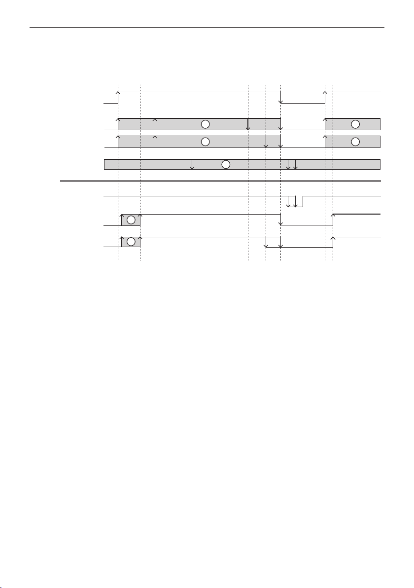
5.2.4 Flush position (Testing)
- See also Chapter 7: K20K21
Safe function of the output relays should also be checked,
as these are located in the evaluation plug-in safety
components in the elevator safety circuit. Testing of the
plug-in system controller breaks the output contact for
approx. 100 ms. This test is carried out after each elevator
trip. The test timing can be controlled with the Flush
position (Bündigstellung) input to avoid any influence on
the elevator control system.
The cegard/Lift offers three test control versions:
1. The output relays are automatically tested 5 s after
Latch_In (Riegel_In) drops out, if the input remains
broken. The test is carried out immediately if a travel
command occurs during this time period.
2. The output relays are automatically tested 10 s after
Latch_In (Riegel_In) drops out, if the input is under a
permanent voltage of >12 VAC/DC. The test is carried
out immediately if a travel command occurs during this
time period.
3. A test is carried out if the input is HIGH in the neutral
status (>12 VAC/DC) and receives a negative edge
when Latch_In (Riegel_In) has dropped out.
The timing of the test can thus be specified by the
elevator control system (e.g. at flush position). It
means, for example, that the Latch_In input will be
frequently bypassed with the ‘Flush’ position input
(Bündigstellung), which leads to a test immediately
after the Latch signal switches to LOW.
5.2.5 Automatic start during power-up
The cegard/Lift automatically carries out a self-test after a
power cut and only closes the safety circuits when the test
has been concluded successfully. The cegard/Lift is ready
for operation after the safety circuits are closed.

cegard/Lift LX/LY English
6 © CEDES | V 2.10
5.2.6 Safety circuit 1 and 2
- See also Chapter 7: K28K29 / K30K31
One of these two contacts must be looped into the elevator
safety circuit so that interruption of the light curtain or a
malfunction will lead to a shutdown of the elevator.
External power contactors with positive-action contact
sets can also be connected to a safety circuit output, and
a single contact should be fed back from each of these
(Chapter 8.3).
These result in the following advantages:
• Switching of higher outputs
• Avoidance of internal safety contact over-loading
• More secure circuits can be realized
5.2.7 Latch output (Latch_Out (Riegel_Out))
- See also Chapter 7: K26K27
A single-phase latch solenoid / motor can be connected
to the K26/K27 connections. Connection of Latch_Out
(Riegel_Out) (in accordance with Chapter 8) is essential
with the cegard/Lift for safety reasons, as it effectively
prevents the elevator leaving a floor and it also avoids a
dangerous step into the elevator cabin from being created
in the event of an interruption of the light curtain.
How is a step prevented? It is possible for the elevator
to “slip” in the unlocking zone if an emergency stop is
activated by an interruption of the light curtain shortly before
reaching this zone. In such an instance, the cegard/Lift
keeps the K26/K27 contacts closed and the door remains
locked, preventing any dangerous step. However, should
this condition exist for a longer period it could lead to the
destruction of the latch solenoid or motor. A maximum
latch holding time of 10 min is defined precisely for this
reason. Latch_Out (Riegel_Out) is adapted to Latch_In
(Riegel_In) after this time period expires. However, the
elevator remains in the emergency stop status.
IMPORTANT NOTICE
The elevator can only be released from its
emergency stop status via an internal call signal
(the reset button) from within the elevator car
itself.
When the emergency stop status has been exited via a
Reset, the cegard/Lift offers three options (Internal Jumper,
see Chapter 8.6):
1. Setting:
Latch_Out (Riegel_Out) remains active for ca.
10 min.
The elevator has to travel to another floor before it can
proceed to the selected floor.
2. Latch_Out (Riegel_Out) drops out with a delay of
2.5 s. Latch_Out (Riegel_Out) succeeds Latch_In if
Latch_In (Riegel_In) is HIGH during these 2.5 s.
3. As in 2. but with a 10 s delay.
The 2.5 s and 10 s settings can only be selected for
elevators equipped with relevelling; otherwise a dangerous
step could result.
Two cegard/Lift versions are available to provide the
Latch_Out (Riegel_Out) output for different elevator
types:
Version LX (with latch contactor)
A power contactor is connected in series to the Latch_
Out (Riegel_Out) output in this version. This can directly
actuate three-phase latch motors (see also Chapter 7.1).
Version LY (with rectifier)
A rectifier module is connected in series to the Latch_Out
(Riegel_Out) output in this version. This can directly
actuate a D.C. latch solenoid (from 180 VDC) (see also
Chapter 7.2).
In order to ensure the Latch control operates properly, the
use of a contactor or rectifier is recommended. The Latch
should never be connected directly via the K26 and K27
contacts as this can interfere with the internal relay.

cegard/Lift LX/LY English
© CEDES | V 2.10 7
5.3 Timing diagrams
5.3.1 General timing diagram
Latch_In
Driving
release
Driving
release
Active
Inactive
Drive Drive
Zone
OFF
Zone
ON
Zone
OFF
Slow Stop
Option 2
Override delay
Flush position
Safety circuit
Latch_Out
Protection field
1
2
3
3
1 1
1
Figure 2: General timing diagram
A change of status of one of these two signals during a journey does not influence the system function.
Light curtain overriding only occurs if both signals are LOW.
A change of status of this signal during a journey does not influence the system function. It is used to test
the safety circuit when the latch has dropped out. The following three versions are possible:
1. The output relays are automatically tested 5 s after Latch_In (Riegel_In) drops out if the input remains
broken. The test is carried out immediately if a travel command occurs during this time period.
2. The output relays are automatically tested 10 s after Latch_In (Riegel_In) drops out if the input is under
a permanent voltage of >12 VAC/DC. The test is carried out immediately if a travel command occurs
during this time period.
3. A test is carried out if the input is HIGH in the neutral status (>12 VAC/DC) and receives a negative
edge when Latch_In (Riegel_In) has dropped out. The timing of breaking the safety circuit can thus be
specified by the elevator controller (e.g. at flush position).
Active : Light curtain interruption causes an emergency stop
Inactive : Light curtain interruption has no effect

cegard/Lift LX/LY English
8 © CEDES | V 2.10
5.3.2 Timing diagram with premature door opening
Latch_In
Active
Inactive
Option 2
Override delay
Flush position
Safety circuit
Latch_Out
Protection field
Drive
Zone
ON
Zone
OFF
Slow Stop Driving
release
Figure 3: Timing diagram (premature door opening)
5.3.3 Timing diagram without premature door opening
Drive
Zone
ON
Zone
OFF
Slow Stop Driving
release
Latch_In
Active
Inactive
Option 2
Override delay
Flush position
Safety circuit
Latch_Out
Protection field
Figure 4: Timing diagram (without premature door opening)
Active : Light curtain interruption actuates an emergency stop
Inactive : Light curtain interruption has no effect
Active : Light curtain interruption actuates an emergency stop
Inactive : Light curtain interruption has no effect

cegard/Lift LX/LY English
© CEDES | V 2.10 9
5.4 Description of light curtain component
The cegard/Lift operates like a through-beam sensor.
It consists of an emitter edge which emits a multitude of
individually-pulsed infrared light beams (Figure 5).
Emitter edge
Receiver edge
Control unit plug-in
Figure 5: Schematic diagram of light curtains
These light beams are received by the receiver edge,
converted to electrical signals and transmitted to the
control unit plug-in. This signals the interruption of a light
beam to its outputs.
5.4.1 Calibration
During calibration the control unit plug-in measures the
transmission output required for each individual light beam
to actuate the respect receivers. The value determined in
this test is increased by approx. 100% and saved for normal
operation. Calibration substantially prevents all too common
reflection in through-beam sensor systems, replacing the
bundling (concentration) of the optical aperture angle usual
in other light barrier systems. This greatly simplifies the
installation / adjustment of optical edges.
The calibration procedure takes between 0.5 and 2 s,
depending on the distance from the emitter and receiver
edges. Calibration is carried out during activation and by
pressing the “T” button on the control unit plug-in. The
control device automatically carries out a calibration if no
change occurs in the protective field during a period of
30 min. Extensive changes in light intensity (e.g. due to
cleaning, etc.) are identified within 3 s and calibrated.
5.4.2 Adjustment
No adjustments are necessary, thanks to the size of the
aperture angle of the optical elements used in the cegard/
Lift light curtain, provided the receiver edge is within the
aperture angle of the emitter edges, and vice-versa (Figure
6).
40°
Ø 5 mm
ER
Figure 6: Aperture angle and beam cross-section
5.4.3 Reflection
Reflections occur if reflective surfaces are located directly
opposite or in the vicinity of the monitoring level, e.g. a tiled
shaft wall (see Figure 7).
Tx Rx
Reflective surface
Optical axis
Min. 5 cm
Figure 7: Reflection
These reflections are eliminated to a large extent by
calibration, the use of the CEDES installation kit and
adherence to minimum distances.
The optical axis must be at least 5 cm from the front edge
of the elevator cabin.
6. Installation
6.1 Installation of opto edges
The following should be observed in general:
Do not mount the emitter and receiver edges twisted
through 180° (e.g. the opto edges’ connection cables
must be conveyed upwards).
Tx
Rx
Tx Rx
Figure 8: Alignment of emitter / receiver

cegard/Lift LX/LY English
10 © CEDES | V 2.10
Do not bend or warp the opto edges. The opto edges
should never be subject to torsion forces.
The opto edges should be at least 5 cm from the front
edge of the elevator cabin.
The connection cable should not be under tension and
should not be crushed.
The connection cable should be well laid and secured.
It should not be in continuous motion or rub against
other objects.
Avoid dirt and scratches.
Fasten the opto edges securely with the screws
provided. If need be, the screws can be secured against
loosening using the usual methods.
Ensure that the emitted light beams of one system are
not directed at the receiver edge of another when using
several light curtains close together. Light curtains
can influence each other under certain circumstances.
The emitter and receiver edges must be arranged on
alternating sides in through-loading elevators for this
reason.
Tx Rx Tx Rx
Tx Rx Tx Rx
Tx Rx Rx Tx
Figure 9: Alignment of multiple light curtains
The opto edges are provided with double-sided adhesive
tape to aid installation and fixing for both flush mounting
and surface installations. These should be used in
conjunction with screws.
For installation purposes, we recommend either the
CEDES flush mounting kit or or its surface mounting
counterpart. These make installing the opto-edges quick
and easy and their side covers help prevent reflection (see
also Chapter 6.3 and 6.4).
6.2 Installation system control rack
The system is located in a control cabinet and is fixed to
the cabin roof with the 4 screws provided or the 2 support
strips included in the delivery.
It is imperative that the following be observed:
Connections K18, K20, K22 and K24 should be
actuated with the positive signal pole (with direct
voltage), connects K19, K21, K23 and K25 with
the negative pole (see Chapter 7, Connection
configuration).
The latch solenoid / motor is operated by the controller.
The vibration should be reduced as much as possible
and the installation should be stable and rigid.
The cable inlet sleeves should be used correctly for
IP54 density. The four rubber packing glands on the
right side are for the connection cables for the opto
edges, the four cable screw fittings on the left being for
the elevator control system connection cables.
Do not plug in or unplug any energized connection
plugs into the control unit plug-in. The device or the
opto edges can be destroyed.
The elevator control system can not be capable of
generating or influencing internal call signals.
No external call signals should be linked to internal call
signals.
The system must be grounded. The “earth” connection
should form a low-resistance connection ≤(10 Ω)
with the ground. Correct grounding of opto edges is
achieved automatically during installation.
6.3 Flush mounting kit
A guard plate is mounted on the inside of the cabin. The
opto edges are mounted on the outside of the cabin
(CEDES Part No.: 100 847).
6.4 Surface mounting kit
If there is not enough space on the outside of the cabin
for the opto edges to be mounted there, they can also
be installed on the inside of the cabin using the surface
mounting kit. There is a loss of approximately 10 cm from
the elevator cabin opening (CEDES part no.: 100 848).
Each mounting kit comes with a detailed manual

cegard/Lift LX/LY English
© CEDES | V 2.10 11
7. Connection configuration
Important safety notice:
The units should only be connected when de-energized!
K1 - K2 Emergency stop alarm detector
K3 - K4 Contact feedback for external latch
contactor. These connections should be
bypassed if an external contactor is not
used.
K5 - K6 Contact feedback for external safety circuit
contactor. These connections should be
bypassed if an external contactor is not
used.
K7 Internal call signal 1, 12 ... 265 VAC / DC
K8 Internal call signal 2, 12 ... 265 VAC / DC
K9 Internal call signal 3, 12 ... 265 VAC / DC
K10 Internal call signal 4, 12 ... 265 VAC / DC
K11 Internal call signal 5, 12 ... 265 VAC / DC
K12 Internal call signal 6, 12 ... 265 VAC / DC
K13 Internal call signal 7, 12 ... 265 VAC / DC
K14 Internal call signal 8, 12 ... 265 VAC / DC
K15 Internal call signals, common potential
K16 - 17 Option 1 (not used)
K18 - 19 Option 2, 12 ... 380 VAC / DC*
K20 - 21 Flush position, 12 ... 380 VAC / DC*
K22 - 23 Override delay
12 ... 380 VAC / DC*
K24 - 25 Latch In, 12 ... 380 VAC / DC*
K26 - 27 Latch Out (Relay-closing contact)
K28 - 29 Safety circuit 1: The circuit is closed if no
error is evident and the system has been
started (“Safety circuit LED” illuminates),
isolated.
K30 - 31 Safety circuit 2, otherwise as safety circuit 1
K32, K33 230 VAC, phase / PEN conductor
K34 Protective earth
*Note polarity when actuating with direct voltage (see
also Chapter 5.4)
SAFETY ADVICE
Overcurrent protection shall be provided
according to DIN EN 60204-1:2019-06 (see
chapter 7).
The electrical equipment shall be wired
according to DIN EN 60204-1:2019-06.
Figure 10: Connection terminals plug-in system controller

cegard/Lift LX/LY English
12 © CEDES | V 2.10
7.1 cegard/Lift LX with latch contactor
The LX version is fitted with a standard contactor with positive-action contacts, allowing the connection of larger latch
motors or latch solenoids. The following circuit diagram clearly illustrates the connection:
Check 1 Riegel
Check 2 Riegel
Riegel Out
Riegel Out
P
PE
N
K27
K26
K4
K3
K32
K33
K34
P
N
K44
K40
K42
K43
K41
PE
K45
Connector
clamps
Connection diagram
Plug-in system
controller
The connection is supplied at terminals K40 and K42
with 230 VAC 50 Hz mains power.
A latch signal up to 16 A / 380 VAC can be
connected to terminals K44 und K45.
A 3-phase motor (3*380) can also be actuated
with little rewiring!
B&W
22
21A1
A2
1 3 5
2 64
1
2
3
B&W
B&W
yellow-green
5
6
4
PE
K40
K41
K42
K43
K44
K45
Figure 11: Latch contactor cegard/Lift LX
7.2 cegard/Lift LY with latch voltage rectifier
The LY version is fitted with a standard rectifier, allowing the connection of direct current latch motors or latch solenoids
(from 180 VDC). The following circuit diagram clearly illustrates the connection:
K3
K4
Check 2 Riegel
Check 1 Riegel
Riegel Out
Riegel Out
K26
K27
P
N
K33
K32
PE
K34
P
N
K40
K42
K43
K41
PE
Connector clamps
Voltage rectifier
yellow-green
4
1
2
3
B&W
Plug-in system controller
~
~
~
~
Connection diagram
The connection is supplied at terminals K40 and K42 with 230 VAC 50 Hz mains power. A DC latch solenoid not exceeding max.
2 A power input can be actuated at the rectifier outputs (±).
Both bypassing jumpers should be removed if another
latch voltage is desired. The required voltage can be
supplied from K40 and K43. Note the contacts’
maximum permitted load currents. If necessary, the
use of a cegard/Lift LX system with downstream,
separate voltage rectifier is recommended.
Figure 12: Latch voltage rectifier cegard/Lift LY

cegard/Lift LX/LY English
© CEDES | V 2.10 13
8. Switching examples
Ensure that suitable interference suppression is provided
when connecting the latch drive and external output
contactors (RC elements or rapid recovery diodes directly
via inductors).
8.1 Connecting a single-phase latch solenoid
N
Latch
solenoid
Mounting rail
P
Connections already
available
K44
K45
K40
K41
K42
K43
Figure 13: Connection diagram latch solenoid
8.2 Connecting a three-phase latch solenoid
A three-phase latch motor can be simply connected by
changing the standard wiring of the cegard/Lift LX. The
following existing connections should be (starting from the
situation in Figure 11) removed: Contactor 2-4, contactor
3-5, contactor 1-K44, contactor 6-K45. The wiring should
be subsequently supplemented in accordance with the
diagram below.
22
21A1
A2
1 3 5
2 64
K45
K40
K41
K42
K43
K44
Mounting rail
Connections already available
N
T
S
R
M
Latch
solenoid
Figure 14: Connection diagram latch solenoid
8.3 Connecting two external output
contactors to safety circuit
Check 1
Sicherheitskreis
Sicherheitskreis 2
Sicherheitskreis 1
Sicherheitskreis 1
Sicherheitskreis 2
Check 2
Sicherheitskreis
K30
K31
K6
K28
K29
K5
P
N
H
H
Si Kr
Figure 15: Connecting two external output contactors to safety
circuit
8.4 Overriding the light curtain
The light curtain is overridden if the Override delay
(Überbrückungsverzögerung) and Option 2 inputs
switch from HIGH to LOW when the elevator arrives at a
floor. The Override delay (Überbrückungsverzögerung)
and Option 2 inputs can be connected parallel with the
Latch_In (Riegel_In) input if required.
-
-
Floor zone signal
P
N
Opener of the
slow-relays
N
P
K22
K23
+ Überbrückungs
verzögerung
Überbrückungs
verzögerung
K18
K19
+ Option 2
Option 2-
-
Figure 16: Overriding the light curtain

cegard/Lift LX/LY English
14 © CEDES | V 2.10
8.4.1 Connecting three internal call signal
buttons
Innenruf 1
Innenruf 2
Innenruf 3
Innenruf
Common
To the elevator
controller
P
N
K7
K8
K9
K15
Figure 17: Connection internal call signal buttons
Internal call signal commands can be allocated to the
existing internal call signal buttons, as the inputs for
internal call signals are impulse edge-triggered and react
to both positive and negative edges. Signal polarity is
irrelevant here.
8.4.2 Connecting a reset button
K7
K15
Innenruf 1
Innenruf
Common
Permanent
voltage
Signal
common
Reset Button
Figure 18: Connection reset button
Permanent voltage: 12 … 265 VAC/DC (see Technical
Data)
8.4.3 Connecting the alarm transmitter
Prewired alarm transmitters can be ordered from CEDES
(CEDES Part No.: 100 849)
K1
K2
brown
white
+ Notstop
- Notstop
Alarm transmitter
Figure 19: Connecting the alarm detector for continuous tone
Connecting the alarm transmitter for intermittent
tone:
For interval tone the two wires are swapped.
(K1: brown, K2: white)
8.5 Avoidance of errors
The following control inputs are high-resistant to enable
their actuation over a broad voltage range:
• Latch_in (Riegel_In)
• Override delay (Überbrückungsverzögerung)
• Flush position (Bündigstellung)
• Option 2
• Internal call signal 1-8 (Innenruf 1-8)
Signals created by capacitive or inductive coupling can, as
a result, lead to errors. It is particularly important to ensure
that the low level at these inputs is less than 5 Volt in every
case (even for short periods of time). Otherwise these
cannot be clearly identified as LOW and, as a consequence,
can lead to errors.
Errors of this nature can be avoided by implementing the
following measures:
Uncouple signals via additional relays
Load the inputs with resistance:
for DC voltage 24 ...110 V R = 47 kΩ / 0.6 W
for AC voltage 230 V R = 120 kΩ / 0.6 W
for AC voltage 380 V R = 500 kΩ / 0.6 W
Inputs should be loaded simultaneously with relays or
contactors
8.6 Latch-stopping time following the ending
of emergency stop via Reset
A plug-in jumper is fitted to the plug-in system controller
PCB and can be used to set the latchstopping time after
the elevator has been released from its emergency stop
status. The stopping time can be set to:
• 2.5 s
• 10 s
• ~10 min (factory settings)
The versions (2.5 s,10 s) should only be selected for
elevators with relevelling, as a dangerous step can
otherwise be created (see also Chapter 5.2.7).
SAFETY ADVICE
Changes to this setting should only be
carried out when the system is de-energized.
Furthermore, the plug-in system controller
should be unscrewed from the housing after
deactivating the mains power supply and all
energized connections. The correct position of
the jumper is indicated on a sticker on the PCB.

cegard/Lift LX/LY English
© CEDES | V 2.10 15
8.7 Example 1 with cegard/Lift LX: Light curtain with dropped-out (released) latch solenoid
actuation
This example shows a simple variant, illustrating how the cegard/Lift LX can be integrated in a system without premature
door opening.
SAFETY ADVICE
Mains power must also be available during a safety circuit interruption. Internal call signals (Innenrufe) must
also be possible during a safety circuit interruption.
Cross reference: See Chapter 5.3.3 for timing diagram
Auswerteeinschub
cegard/Lift
Inside calls or
Reset button
Door lock signal
Power supply
Latch solenoid
Safety circuit
Inside calls /
Reset button,
Reference potential
To the elevator control
P
N
PE
Überbrückungsverzögerung
Bündigstellung
Sicherheitskreis
Power
Servicetaste
Check 1 Riegel
+ Notstop
Check 2 Sicherheitskreis
Check 1 Sicherheitskreis
Check 2 Riegel
- Notstop
- Überbrückungsverzögerung
+ Überbrückungsverzögerung
- Bündigstellung
+ Bündigstellung
+ Option2
- Option1
- Option1
+ Option1
Innen-Ruf Common
Innenruf 1-8
-Riegel_in
+ Riegel_in
Riegel_out
Sicherheitskreis 1
Sicherheitskreis 2
Diagnose
K10
K1
K2
K3
K4
K5
K5
K9
K8
K7
K15
K14
K13
K12
K11
K16
K21
K20
K19
K18
K17
K33
K32
K31
K30
K29
K28
K27
K26
K25
K24
K23
K22
K34
P
N
K40
K42
K41
K43
K44
K45
Snap-rail
Figure 20: Connection diagram without premature door opening

cegard/Lift LX/LY English
16 © CEDES | V 2.10
8.8 Example 2 with cegard/Lift LX: Bypassed light curtain in floor zone
This example shows another variant, illustrating how the cegard/Lift LX can be integrated in a system. The difference
to Example 1 is that the light curtain is bypassed somewhat earlier. The light curtain is thus overridden 10 cm prior
to the flush position in the case of an elevator with a landing zone of ±10 cm. This variant is recommended, as many
elevator users try to open the door while travelling slowly. This connection does not trigger an emergency stop under the
conditions described, provided the elevator is already within the floor zone.
SAFETY ADVICE
Mains power must also be available during a safety circuit interruption. Internal call signals (Innenrufe) must
also be possible during a safety circuit interruption.
Cross reference: See Chapter 5.3.2 for timing diagram
Auswerteeinschub
cegard/Lift
Inside calls or
Reset button
Door lock signal
i.e. slow relay
Zone switch
Power supply
Latch solenoid
Safety circuit
Inside calls /
Reset button,
Reference potential
To the elevator control
P
N
PE
Überbrückungsverzögerung
Bündigstellung
Sicherheitskreis
Power
Servicetaste
Check 1 Riegel
+ Notstop
Check 2 Sicherheitskreis
Check 1 Sicherheitskreis
Check 2 Riegel
- Notstop
-
-
+
Überbrückungsverzögerung
+ Überbrückungsverzögerung
- Bündigstellung
+ Bündigstellung
+ Option2
- Option1
- Option1
+ Option1
Innen-Ruf Common
Innenruf 1-8
-Riegel_in
+ Riegel_in
Riegel_out
Sicherheitskreis 1
Sicherheitskreis 2
Diagnose
K10
K1
K2
K3
K4
K5
K5
K9
K8
K7
K15
K14
K13
K12
K11
K16
K21
K20
K19
K18
K17
K33
K32
K31
K30
K29
K28
K27
K26
K25
K24
K23
K22
K34
P
N
K40
K42
K41
K43
K44
K45
Snap-rail
Figure 21: Connection diagram for early override

cegard/Lift LX/LY English
© CEDES | V 2.10 17
8.9 Example 1 with cegard/Lift LY: Bypassed light curtain with dropped-out (released) latch
solenoid actuation
This example shows a simple variant, illustrating how the cegard/Lift LY can be integrated in a system without premature
door opening.
SAFETY ADVICE
Mains power must also be available during a safety circuit interruption. Internal call signals (Innenrufe) must
also be possible during a safety circuit interruption.
Cross reference: See Chapter 5.3.3 for timing diagram
Auswerteeinschub
cegard/Lift
Inside calls or
Reset button
Door lock signal
Power supply
Latch solenoid
Safety circuit
Inside calls /
Reset button,
Reference potential
To the elevator control
P
N
PE
Überbrückungsverzögerung
Bündigstellung
Sicherheitskreis
Power
Servicetaste
Check 1 Riegel
+ Notstop
Check 2 Sicherheitskreis
Check 1 Sicherheitskreis
Check 2 Riegel
- Notstop
- Überbrückungsverzögerung
+ Überbrückungsverzögerung
- Bündigstellung
+ Bündigstellung
+ Option2
- Option1
- Option1
+ Option1
Innen-Ruf Common
Innenruf 1-8
-Riegel_in
+ Riegel_in
Riegel_out
Sicherheitskreis 1
Sicherheitskreis 2
Diagnose
K10
K1
K2
K3
K4
K5
K5
K9
K8
K7
K15
K14
K13
K12
K11
K16
K21
K20
K19
K18
K17
K33
K32
K31
K30
K29
K28
K27
K26
K25
K24
K23
K22
K34
P
N
K40
K42
K41
K43
Snap-rail
+
-
Figure 22: Connection diagram without premature door opening

cegard/Lift LX/LY English
18 © CEDES | V 2.10
8.10 Example 2 with cegard/Lift LY: Bypassed light curtain in the zone
This example shows another variant illustrating how the cegard/Lift LY can be integrated in a system. The difference to
Example 1 is that the light curtain is bypassed somewhat earlier. The light curtain is thus overridden 10 cm prior to the
flush position in the case of an elevator with a zone of ±10 cm. This variant is recommended, as many elevator users try to
open the door while travelling slowly. This connection does not trigger an emergency stop under the conditions described,
provided the elevator is already within the floor zone.
SAFETY ADVICE
Mains power must also be available during a safety circuit interruption. Internal call signals (Innenrufe) must
also be possible during a safety circuit interruption.
Cross reference: See Chapter 5.3.2 for timing diagram
Auswerteeinschub
cegard/Lift
Inside calls or
Reset button
Door lock signal
i.e. slow relay
Zone switch
Power supply
Latch solenoid
Safety circuit
Inside calls /
Reset button,
Reference potential
To the elevator control
P
N
PE
Überbrückungsverzögerung
Bündigstellung
Sicherheitskreis
Power
Servicetaste
Check 1 Riegel
+ Notstop
Check 2 Sicherheitskreis
Check 1 Sicherheitskreis
Check 2 Riegel
- Notstop
-
-
+
Überbrückungsverzögerung
+ Überbrückungsverzögerung
- Bündigstellung
+ Bündigstellung
+ Option2
- Option1
- Option1
+ Option1
Innen-Ruf Common
Innenruf 1-8
-Riegel_in
+ Riegel_in
Riegel_out
Sicherheitskreis 1
Sicherheitskreis 2
Diagnose
K10
K1
K2
K3
K4
K5
K5
K9
K8
K7
K15
K14
K13
K12
K11
K16
K21
K20
K19
K18
K17
K33
K32
K31
K30
K29
K28
K27
K26
K25
K24
K23
K22
K34
P
N
K40
K42
K41
K43
Snap-rail
+
-
Figure 23: Connection diagram for early override

cegard/Lift LX/LY English
© CEDES | V 2.10 19
9. Commissioning
9.1 General description
The opto edges are connected to the control unit plug-in
after installation. The plug with the blue marking (receiver
edge) is inserted into the “receiver” socket, the plug with
the white marking (emitter edge) being inserted into the
“emitter” socket. The plugs are coded and cannot be
inserted incorrectly or in the wrong sockets. Ensure that
both of the plug’s safety jacks engage correctly.
The plug can be removed again by pressing the two safety
clips. The final step is connecting the connectors (K28 …
K34; observe connection configuration).
It goes without saying that opto edges should always be
connected in pairs to each of the control unit plug-ins in
cases of through-loading elevators.
The plug-in system controller and the control unit plug-ins
are controlled by their own microprocessors. These test the
entire system after activation. The following procedures
occur during this:
The following symbols appear consecutively on the plug-
in system controller:
For elevators with one entrance:
L _ I U 3 I 2
For through-loading elevators:
L _ 2 U 3 I 2
A bar then circles around on the display until the self-test
is completed. An For Uappears if the test is successful,
depending on whether the light curtain is bypassed or not.
The LED “Alarm T” and “Alarm R” flash alternately with
approx. 1 Hz for approx. 10 s on the control unit plug-in
while the self-test is in progress.
on
on
off
off
LED
Alarm R
LED
Alarm T
t
2
t
3
t
1
= Approx. 10 s (self test)
= Approx. 2 s
= Ready for operation
t
1
t
2
t
3
Figure 24: Behaviour after control unit plug-in power-up
Both LEDs subsequently illuminate continuously for
approx. 2 s. The light curtain is calibrated during this
time period. The two LEDs “Alarm T” and “Alarm R” are
then extinguished. The relevant control unit plug-in and
associated opto edges are now ready for operation. Both
control unit plug-ins undergo this procedure in the case of
throughloading elevators.
9.2 Installation check
SAFETY ADVICE
The items listed in this chapter are relevant to
safety and must be checked when accepting
an elevator. Failure of the installation
conducted to match the points below should
be adjusted immediately.
Check with local elevator inspection
authorities if different or additional installation
requirements have to be considered.
The distance between the sensors and the front edge of
the cabin is 100 mm (tolerance ±50 mm).
The lowest beam can be placed at a maximum of
30 mm above the cabin floor when the distance to
the front edge is between 50 mm and 100 mm. If the
sensor is located between 100 mm and 150 mm from
the front edge of the cabin, the lowest beam can be
placed between 30 mm and a maximum of 50 mm
above the cabin floor.
The height monitored is at least 1,500 mm.
The sensor grid is ≤250 mm.
The danger zones are marked with black and yellow.
Both sensor connection cables are conveyed upwards
away from the cabin.
The system control rack is correctly grounded ≤ (10 Ω)
9.3 Function test
Correct integration of the cegard/Lift should now be
checked. These tests should be conducted during the
initial installation and after every elevator inspection. They
help the elevator technician check the wiring and correct
operation of the unit.
9.3.1 Test procedure
Individual procedures are approached step by step during
the test. It is important that the sequence described be
adhered to, as the desired points may otherwise not
be tested in certain circumstances. Any error resulting
in the failure of a test point should be remedied and the
procedure should be recommenced from the first test.
A minimum of two people are required to conduct these
tests. (one person in the cabin, one person outside (e.g.
caretaker)).
NOTICE
No third person or any other object should
be in the elevator during commissioning or
inspection!

cegard/Lift LX/LY English
20 © CEDES | V 2.10
9.3.2 Testing
Procedure, test Correct reaction Measures in event of wrong reaction
Safety circuit integration
Internal: Protection area is free
Internal: Select other floor (travel
command / reset)
Internal: Interrupt light curtain
during journey
The elevator must stop immediately
if the light curtain is penetrated.
Loop safety circuit 1 into the elevator
safety sequence.
Check that the override signal sequence
is correct (see Chapter 5).
Internal call signal wiring
Internal: Enable light curtain
External: Call elevator with external
call
The elevator should not continue
the journey. It should remain
stationary.
An external call signal should not be
carried out on the system control rack.
Deactivate external call signal with
contact (K30/K31) if necessary.
Internal: Select other floor (travel
command)
The elevator should start moving
and stop at the selected floor.
Check internal call signal wiring (no
level?)
Latch_Out (Riegel_out) wiring
Internal: Light curtain interrupted
Internal: Select other floor (travel
command
The elevator should remain
stationary. It should not move.
The door should be locked.
Loop in Latch_Out (Riegel_Out) (see
Chapter 4.2.7).
Internal: Enable light grid repeat
travel command
The elevator should start moving
and stop at the selected floor.
Step test
Internal: Attempt to induce an
emergency stop shortly before the
zone so that the elevator slips within
the zone (see Chapter 5.2.7)
It should be impossible to open the
landing door.
Check overall integration of system and
elevator signals.
Internal: Select the same floor again
while the light curtain is enabled.
(travel command / reset) and wait
briefly.
It should only be possible to open
the landing door if the cabin is flush
with it. No step should be visible!
Plug in latch stopping time jumper at
10 min.
The latch stopping time should only
be set at 2.5 or 10 s for elevators with
recall!
10. Display and operating elements
10.1 Tumbler switch on control unit plug-in
A tumbler switch is located on the front of the control unit
plug-in which has a central position, a contact function to
the left and a switch function to the right.
10.1.1 Normal operating mode
The tumbler switch is at “0” (central position).
10.1.2 Operation with buzzer
The buzzer is switched on in the “Loudspeaker” position (to
the right). This operating mode is used for an audible check
during the installation.
10.1.3 Test
A calibrating procedure is conducted when the button on
“T” is actuated (to the left). The LED’s “Alarm T” and / or
“Alarm R” illuminate simultaneously for the duration of the
calibration. The monitored area should be empty during
this time period. The relay will not enable if the control unit
plug-in detects covered elements, defective transmitters or
defective receivers.
10.2 Tumbler switch on plug-in system
controller (Service button)
A tumbler switch is located on the front of the plug-in
system controller. Actuating this “service button” has
the same function as an internal call signal. The elevator
technician can close the safety circuit again from the
plug-in system controller in the event of an emergency
stop during commissioning and inspection control during
installation.
10.3 “Status” output on control unit plug-in
(Loading or door control)
The ‘Status’ output continuously indicates the status of
the light curtain and can be used to control an automatic
landing door or for load control. The switch relay (CEDES
Part No.: 100 098) is available as an accessory for this
purpose.
Table of contents
Languages: