TIELBURGER tw50 User manual


Trademark
This document is a publication by Julius Tielbürger GmbH & Co. KG, Postdamm 12, D-32351 Stemwede-Oppenwehe, Germa-
ny (www.tielbuerger.de).
The document is up to date with the latest technology at the time of printing. Subject to technical and equipment changes. The
drawings and illustrations shown may differ from the original.
$OOULJKWVUHVHUYHGLQFOXGLQJWKRVHRIWUDQVODWLRQ$Q\W\SHRIUHSURGXFWLRQVXFKDVSKRWRFRS\PLFUR¿OPRUVWRULQJLQHOHF-
tronic data processing systems, requires written authorisation from the publisher. Any reproduction, whether in whole or in
part, is prohibited.
All trademarks, registered trademarks, trade names and brand names are the property of their rightful owners and are acknowl-
edged by us.
© Copyright 2017 by Julius Tielbürger GmbH & Co. KG

3
Content
1 Operating instructions.................................................................................................................................................... 4
1.1 General ...................................................................................................................................................................... 4
1.2 Warnings and symbols............................................................................................................................................... 5
2 Basic safety instructions ................................................................................................................................................. 6
2.1 Intended use............................................................................................................................................................... 6
2.2 Organisational measures............................................................................................................................................ 6
3HUVRQQHOVHOHFWLRQDQGTXDOL¿FDWLRQVEDVLFREOLJDWLRQV.......................................................................................... 7
3 Scope and condition of delivery..................................................................................................................................... 8
4 Illustration of the machine and danger zone, component description and position of safety stickers .................. 9
5 Installation..................................................................................................................................................................... 10
6 Start-up .......................................................................................................................................................................... 14
6.1 Basic safety instructions for normal operation........................................................................................................ 14
6.2 Operating the machine in winter ............................................................................................................................. 14
6.3 Adjusting the height of the handlebar...................................................................................................................... 15
6.4 Bristle pressure ........................................................................................................................................................ 16
6.5 Brush drive .............................................................................................................................................................. 17
6.6 tw50s steerable freewheel ....................................................................................................................................... 18
6.7 Starting/switching off the engine (quick guide) ...................................................................................................... 19
6.8 Charging the B&S InStart battery ........................................................................................................................... 21
6.9 Connecting the battery to the engine....................................................................................................................... 24
6.10 Starting/switching off the engine........................................................................................................................... 25
6.11 Disconnecting the battery from the engine............................................................................................................ 26
6.12 Support roller (accessory) ..................................................................................................................................... 27
6.13 tw50 lateral protective cover (accessory).............................................................................................................. 27
7 Maintenance and care.................................................................................................................................................. 28
7.1 Basic safety instructions.......................................................................................................................................... 28
7.2 Refuelling ................................................................................................................................................................ 29
7.2 Refuelling ................................................................................................................................................................ 30
7.3 Checking the oil....................................................................................................................................................... 31
7.4 Battery and charger.................................................................................................................................................. 32
7.5 Replacing the twisted knot brushes ......................................................................................................................... 33
7.6 Cleaning the implement........................................................................................................................................... 35
7.7 Setting and readjusting the Bowden cables............................................................................................................. 36
7.8 Checking and correcting the tyre pressure .............................................................................................................. 37
&OHDQLQJWKHDLU¿OWHU............................................................................................................................................... 38
7.10 Storage................................................................................................................................................................... 38
7.11 Maintenance plan................................................................................................................................................... 38
8 Faults and how to rectify them .................................................................................................................................... 39
9 Transport ....................................................................................................................................................................... 41
7HFKQLFDOVSHFL¿FDWLRQV............................................................................................................................................... 42
7HFKQLFDOVSHFL¿FDWLRQV............................................................................................................................................... 43
11 EC Declaration of Conformity................................................................................................................................... 44

These operating instructions are intended to help users
familiarise themselves with the machine and use it in
line with its intended applications.
The operating instructions contain important informa-
tion on how to operate the machine safely, properly and
economically. Observing these operating and installa-
tion instructions helps to avert risks, to reduce repair
costs and downtime and to increase the reliability and
service life of the machine.
The operating instructions must be supplemented by
the relevant national rules and regulations for accident
prevention and environmental protection.
The operating instructions must always be available
wherever the machine is in use.
1.1 General
The operating instructions must be read and applied
by any person in charge of carrying out work with or
on the machine, such as:
2SHUDWLRQ LQFOXGLQJ VHWWLQJ XS IDXOW UHFWL¿FDWLRQ
in the course of work, removal of production waste,
maintenance and disposal of operating and auxiliary
materials
-Maintenance (servicing, inspection, repair) and/or
-Transport.
The generally recognised rules of technology for safe
and proper working must be observed in addition to
the operating instructions and mandatory regulations
for accident prevention which apply to the country
and place of use.
Operating instructions
1 Operating instructions
4
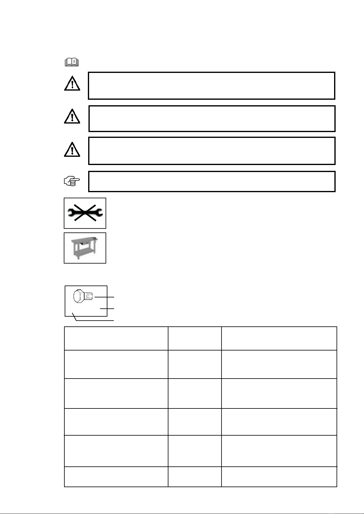
Read the operating instructions
1.2 Warnings and symbols
DANGER!
Indicates an immediate threat of danger. If this instruction is ignored, there is a risk of death
or extremely serious injury.
WARNING:
Indicates a potentially hazardous situation. If this instruction is ignored, there may be a risk
of death or extremely serious injury.
CAUTION:
Indicates a potentially hazardous situation. If this instruction is ignored, there may be a
risk of minor injury.
IMPORTANT:
Indicates operating tips and other useful information.
5
Operating instructions
Work on a workbench
Do not use a tool
Symbol
Type
Quantity
2x M8 x 20
Symbol
Bolt
Washer
Nut
Combination spanner
Hexagon head screwdriver
Screwdriver
Crosshead screwdriver
Example
types:
M8 x 16
8,1 - 58 - 5
M8 (L)
8
PZ 2
PH 2
Explanation
M=Metric
S=Diameter in mm
16 =Length in mm
8.1 =Inner diameter
58 =Outer diameter
5 =Material thickness in mm
M=Metric
8 =Inner diameter in mm
(L) =Lock nut
8 =Size in mm
PZ 2 = Pozidriv size 2
PH 2 = Phillips size 2

2.2 Organisational measures
The operating instructions must always be to hand
wherever the machine is in use.
In addition to the operating instructions, observe and
follow the generally valid legal regulations and any
other binding regulations for accident prevention and
environmental protection.
Such obligations may also include handling hazard-
ous substances or making available/wearing personal
SURWHFWLYHHTXLSPHQWDQGFRPSO\LQJZLWKURDGWUDI¿F
regulations, for example.
Supplementthe operating instructions withinstructions
including site management and reporting obligations
concerning special operational requirements, for ex-
DPSOHZLWKUHJDUGWRZRUNRUJDQLVDWLRQZRUNÀRZV
personnel used, etc.
Any personnel instructed to perform work on the ma-
chine must have read the operating instructions before
VWDUWLQJZRUNVSHFL¿FDOO\WKHVHFWLRQHQWLWOHG6DIHW\
LQVWUXFWLRQV5HDGLQJWKHLQVWUXFWLRQVDIWHUZRUNKDV
begun is too late. This applies in particular to person-
nel who only work on the machine occasionally, for
example for set-up and maintenance.
At least occasionally, check that the personnel are
working with safety and hazards in mind and are fol-
lowing the operating instructions.
Personnel must not have long hair which is not tied
back or wear loose clothing or jewellery including
rings. There is a risk of injury from being caught or
drawn into the machine, for example.
Wear personal protective equipment if necessary or
required by regulations.
Observe all safety and hazard notices on the machine.
Ensure that all safety and hazard notices at/on the
machine can be read in full at all times.
,QWKHHYHQWRIDQ\PRGL¿FDWLRQWRWKHPDFKLQHRUDQ\
change in the machine's performance that may affect
safety, shut down the machine immediately and report
WKHIDXOWWRWKHUHVSRQVLEOHLQGLYLGXDORURI¿FH
Do not modify, convert or attach equipment to the ma-
chine without approval from the supplier if this could
LPSDLUVDIHW\7KLVDOVRDSSOLHVWR¿WWLQJDQGDGMXVWLQJ
safety equipment and valves, as well as for welding
on supporting parts.
6SDUHSDUWV PXVWIXO¿OWKHWHFKQLFDOUHTXLUHPHQWV
determined by the manufacturer. This must always be
guaranteed for genuine spare parts.
Adhere to the prescribed time periods or those indi-
cated in the operating instructions for recurring tests/
inspections.
Workshop equipment which is appropriate for the work
is mandatory for carrying out maintenance measures.
0DNH SHUVRQQHO DZDUH RI WKH ORFDWLRQ RI ¿UH H[WLQ-
guishers and how to use them.
2EVHUYHWKH¿UHDODUPDQG¿UH¿JKWLQJSURFHGXUHV
2.1 Intended use
The machine has been constructed using state-of-the-
art technology and in line with the recognised technical
safety regulations. However, use of this machine may
still result in the risk of injury or death to the user or
third parties, or of damage to the machine and other
material assets.
Only use the machine in technically perfect working
order, for its intended use and with safety and hazards
in mind, in compliance with the operating instructions.
In particular, you must immediately rectify faults that
FRXOGLPSDLUVDIHW\RUKDYHVXFKIDXOWVUHFWL¿HGLP-
mediately by a third party.
The machine is solely intended for the removal of
weed growth on paved, concrete and/or tarmac sur-
faces outdoors. Any other or additional form of use
is considered non-compliant with the intended use.
For example, the machine must not be used to sweep
animal feed. Twisted knot brushes can come loose and
be consumed by animals, causing harm to them. The
manufacturer/supplier shall not be held liable for any
damage or loss suffered as a result. The risk is borne
solely by the user. Intended use also includes comply-
ing with the operating instructions and adhering to the
inspection and maintenance conditions.
The machine may only be operated with twisted knot
brushes that have been approved by the manufacturer.
Basic safety instructions
2 Basic safety instructions
6

3HUVRQQHOVHOHFWLRQDQGTXDOL¿FDWLRQVEDVLFREOLJDWLRQV
Work on/with the machine may only be carried out by
reliable personnel. Observe the legal minimum age.
Only use trained or instructed personnel and clearly
GH¿QHWKHUHVSRQVLELOLWLHVRIWKHSHUVRQQHOIRURSHUD-
tion, set-up, maintenance and repair.
Ensure that only authorised personnel work on the
machine.
Appoint an operator responsible for the machine –
LQFOXGLQJZLWKUHJDUGWRWUDI¿FUHJXODWLRQV±DQGJLYH
them the authority to refuse instructions issued by third
parties that may cause a hazard.
Only allow personnel who are yet to complete training,
instruction and induction or who are still completing
ageneral apprenticeship to carry out work on the
machine under the constant supervision of an expe-
rienced person.
Work on the machine's electrical equipment may only
EHFDUULHGRXWE\DTXDOL¿HGHOHFWULFLDQRUE\WUDLQHG
personnel under the guidance and supervision of a
qualified electrician in accordance with electrical
engineering regulations.
Work on chassis, braking and steering systems must
RQO\EHFDUULHGRXWE\TXDOL¿HGSHUVRQQHOWUDLQHGIRU
such work.
Clean the implement regularly, particularly in the ex-
haust and engine area. Otherwise, there is an increased
ULVNRI¿UH
Basic safety instructions
7

Scope and condition of delivery
8
4) Please recycle the packaging material .
The product is delivered in a collapsible box:
1 Weed brush
1 Accessories bag containing
- Operating instructions
- Operating instructions for the engine
Accessories (must be ordered separately)
- Impact guard
- Support roller
3 Scope and condition of delivery
1) Product packaging 2) Inspect the original packaging
3) tw50s weed brush as-delivered condition

Installation
5 Installation
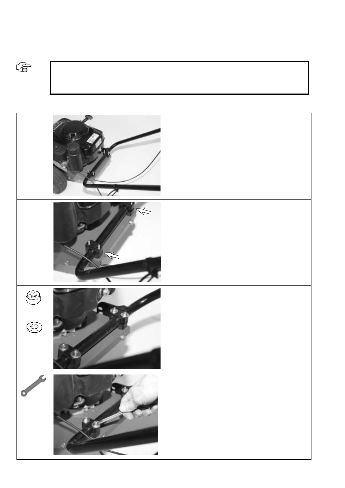
IMPORTANT:
'RQRW¿OOWKHHQJLQHZLWKDQ\RLORUSHWURODWWKLVSRLQW
Before you begin, acquire an overview of the installation sequence and the required parts and tools.
10
Position the handlebar.
Place the handlebar on the pipe brackets.
Place the pipe brackets onto the bolts.
Preassemble the handlebar with the washer and lock nut.
Only tighten the nuts to the point that the handlebar can still
move without dropping on its own.
4x M6
4x 6.4-16-1.6

11
Installation
Attach the washer.
Screw down the nut.
Undo the star grip.
Adapt the height of the handlebar to the height of the op-
erator.
Insert the hex bolt with washer.
Install the throttle regulation lever.
Position the throttle cable.
Secure the handlebar using the star grip.
1 x 6x65 x 20
1x M6
2x 6.4-12-1.6

Installation
12
Tighten the bolt.
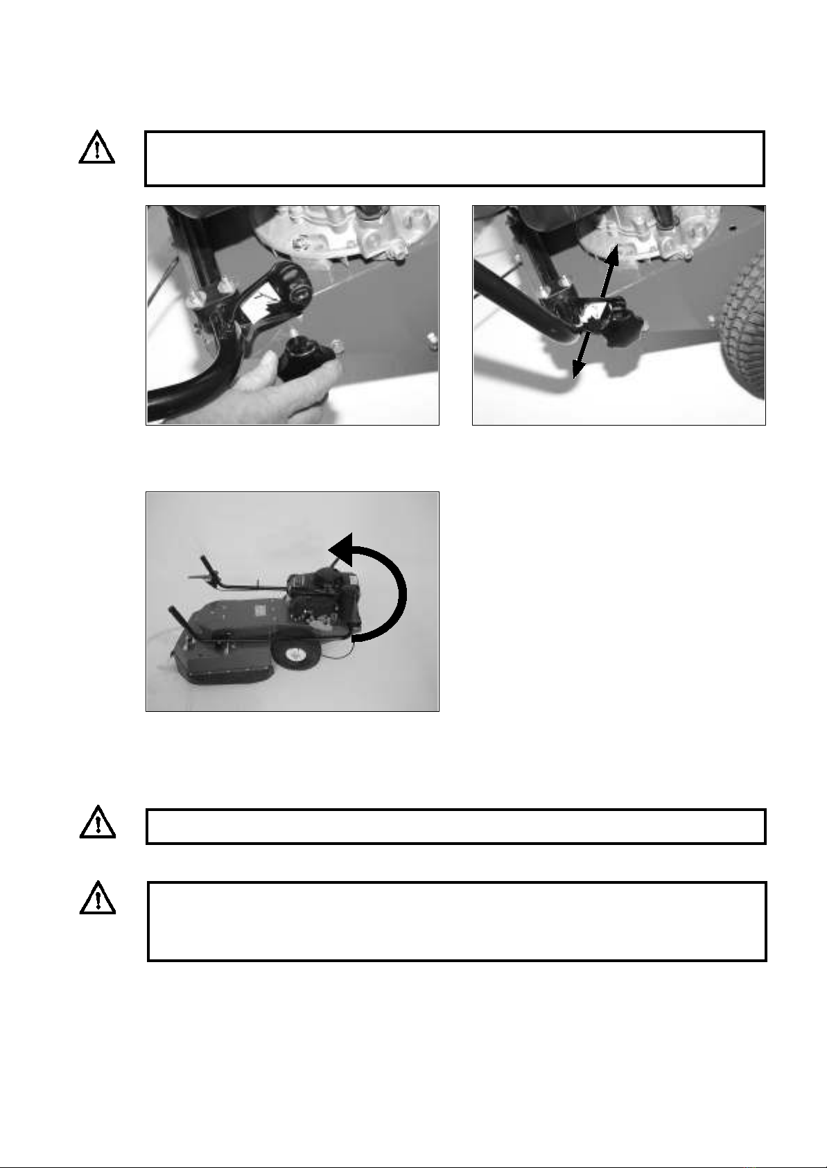
Install the clutch lever.
Undo the hex socket bolt.
Keep the lateral grip pushed down.
Position both halves of the lever on the handlebar pipe
so that they can be connected to each other.
IMPORTANT:
Push down the lateral grip to prevent the com-
pression spring jumping out.

Installation
13
Tighten the hex socket bolt.
Correctly installed clutch lever.
Connect the two halves of the lever.
IMPORTANT:
Check that the lateral grip works properly.

6.1 Basic safety instructions for normal operation
6 Start-up
Never operate the machine in a manner that could
compromise safety.
Before beginning work, familiarise yourself with the
work environment at the location where the machine
is used. The work environment includes, for example,
REVWDFOHVLQWKHZRUNDQGWUDI¿FDUHDWKHORDGEHDULQJ
FDSDFLW\RIWKHÀRRUDQGWKHUHTXLUHGPHDQVRIFRUGRQ-
ing the location where the machine is used off from
WKHSXEOLFWUDI¿FDUHD
Take appropriate measures to ensure that the machine is
only operated in a safe and fully functional condition.
Only operate the machine when all protective equip-
ment and safety-critical equipment, for example
detachable protective equipment, sound-insulating
equipment and extraction equipment, is present and
in proper working order.
Always check for externally visible damage and de-
fects before using the machine. Report any machine
PRGL¿FDWLRQVLQFOXGLQJFKDQJHVLQSHUIRUPDQFHLP-
PHGLDWHO\WRWKHRI¿FHSHUVRQUHVSRQVLEOH6KXWGRZQ
the machine immediately and secure it if necessary.
In the event of a malfunction, shut down and secure
WKHPDFKLQHLPPHGLDWHO\ +DYHIDXOWV UHFWL¿HG LP-
mediately.
Only start the machine from the driver's seat.
Switch the machine on and off in accordance with the
operating instructions, observing the control displays.
Before switching on/starting up the machine, ensure
that no one can be endangered by the machine starting
up.
Beforetravelling withthemachineorbeginning work,
check that the brakes, steering, signal and lighting
systems are fully functional.
Before moving the machine, always check thatthe
accessories are securely in place.
When driving on public roads and paths and in public
SODFHVFRPSO\ZLWKWKHDSSOLFDEOHURDGWUDI¿FUHJX-
lations and bring the machine into a condition which
LVSHUPLWWHGE\URDGWUDI¿FUHJXODWLRQVLQDGYDQFH
,QSRRUYLVLELOLW\RULQWKHGDUNDOZD\VHQVXUHVXI¿-
cient lighting.
Always maintain an adequate distance from pit edges
and slopes.
Prohibit any manner of working that may impair the
stability of the machine.
'R QRWGULYHDFURVV VORSHVDOZD\V WUDQVSRUWZRUN
equipment and loaded goods close to the ground,
particularly when descending hills.
Always adapt your driving speed to the conditions
on sloping terrain. Never change to a lower gear on a
VORSH\RXVKRXOGGRWKLVEHIRUH\RXUHDFKWKHVORSH
Upon leaving the machine, always secure it against
accidentally rolling away and unauthorised use.
Start-up
14
6.2 Operating the machine in winter
&KHFNLIWKHDLU¿OWHULVGU\DWUHJXODULQWHUYDOV,IWKH
¿OWHULVGDPSEHFDXVHRIFRQGHQVDWLRQDOORZLWWRGU\
RYHUQLJKW2WKHUZLVHWKHUHLVDFKDQFHWKDWWKHDLU¿OWHU
will freeze and the engine will not start. Before start-up,
spray the throttle cable, throttle regulation lever and
the linkage on the engine with silicone spray. Move
the throttle regulation lever into both end positions so
that the Bowden pull cable on the engine and on the
throttleregulation lever is lubricated as well. This pre-
vents frozen condensation obstructing the mechanics.
Siliconesprayis recommendedformaintaining the
Bowden pull cables on the other levers as well.
After sweeping, clear any snow off the machine using
a brush.
IMPORTANT:
Store the machine in a room protected from frost. Prevent the machine freezing. If a component has
been frozen solid, this could damage the machine.
Silicone spray attracts dust. This means that it is only suitable as a care product in the winter when
there is snow.
DANGER!
1HYHUVSUD\VLOLFRQHVSUD\RQWKHHQJLQHZKLOHLWLVKRW7KLVFRXOGFDXVHD¿UH)ROORZWKHLQVWUXF-
tions on the spray can.
CAUTION:
Switch off the engine and allow it to cool down. Secure the machine to prevent it from being started
inadvertently.
CAUTION: Make sure that the star grip is securely tightened.
1) Undo the star grip and select the required position.
6.3 Adjusting the height of the handlebar
2) Note the settings available.
CAUTION:
Switch off the engine. Secure the machine to prevent it from being started inadvertently.
Start-up
15
3)You can fold the handlebar all the way forward and
therefore reduce the amount of space required by
the machine for storage purposes or when it needs
to be set aside temporarily.
DANGER!
Wearing clothing with loose sleeves runs the risk of the handlebar grip becoming caught in the
sleeve. This can prevent the gear lever disengaging. Wear appropriate clothing. It may help to set
the handlebar to a lower position.

6.4 Bristle pressure
Start-up
3) Remove the linchpin. Set the required height.
1) The bristle pressure can be adjusted. This is why
the height of the support wheel is adjustable.
2) Adjusting the height of the bristles
The height is adjusted by rearranging the washers.
IMPORTANT:
If you are using a badly worn brush or working on cobblestones, lower the brush by an additional
washer.
Please note: Excessive brush pressure impairs cleaning effectiveness because the bristles will be
too bent.
Reduce the pressure on the brushes after each use. Raise the brush.
4) Reinsert the linchpin.
16
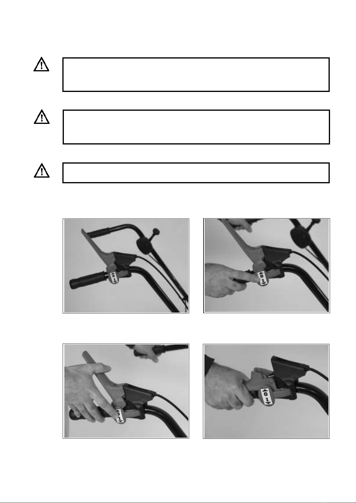
6.5 Brush drive
4)Operating the gear lever switches on the brush
drive.
Start-up
CAUTION:
7KHKDQGOHEDUPXVWEH¿UPO\VHFXUHGDWWKHUHTXLUHGKHLJKW
2) Unlock the lever.
17
3) Move the lever into position.
1)The gear lever for the sweeper brush drive is located
on the handlebar.
DANGER!
Wearing clothing with loose sleeves runs the risk of the handlebar grip becoming caught in the
sleeve. This can prevent the gear lever disengaging. Wear appropriate clothing. It may help to set
the handlebar to a lower position.
WARNING:
Ensure that no persons or property are located in the danger zone, as otherwise this could result in
injury or material damage. Secure the machine to prevent it from being started inadvertently.

18
6.6 tw50s steerable freewheel
Start-up
1. Engage the steerable freewheel: Insert the linchpin
through the axle only.
2)Disengagethesteerablefreewheel: Insertthelinch-
pin through the axle and the hub (e.g. for sweeping
on inclines)
WARNING:
Switch off the engine. Secure the machine to prevent it from being started inadvertently.
7KHZHHGEUXVKLV¿WWHGZLWKDVWHHUDEOHIUHHZKHHO7KLVPDNHVLWHDVLHUWRWXUQWKHZHHGEUXVK
.
6.7 Starting/switching off the engine (quick guide)
Start-up
IMPORTANT:
%HIRUHVWDUWLQJWKHHQJLQHSOHDVHFKHFNWRHQVXUHWKDWWKHHQJLQHFUDQNFDVHLV¿OOHGZLWKDVXI¿FLHQW
TXDQWLW\RIRLO)RUUHDVRQVUHODWLQJWRWUDQVSRUWWKHHQJLQHLVQRWVXSSOLHG¿OOHGZLWKHQJLQHRLOZKHQ
the sweeper is delivered.
DANGER!
1HYHUDOORZWKHHQJLQHWRUXQLQFORVHGRUFRQ¿QHGVSDFHV7KHH[KDXVWJDVHVFRQWDLQSRLVRQRXV
carbon monoxide gas. Ensure that the travel drive and brush drive are switched off.
The handlebar must be securely locked at the required height.
Read the operating instructions provided by the engine manufacturer.
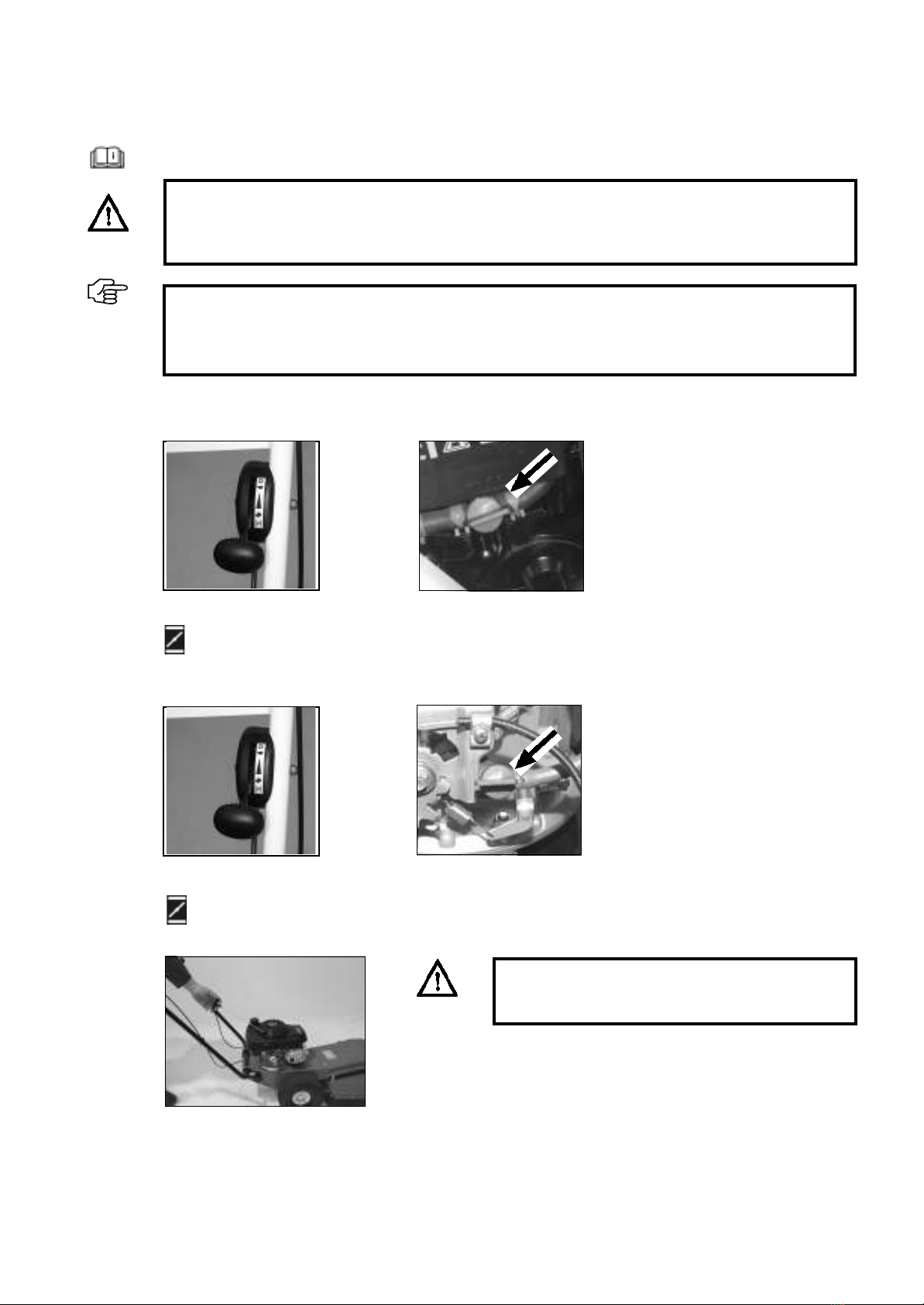
1. Starting the engine
1) Move the throttle regu-
lation lever to
2) Open the fuel cock (on the
right of the engine in the
direction of travel).
3) Pull on the starter cable. En-
sure that you are behind the
handlebar and outside of the
danger zone.
19
the choke position.
Briggs & Stratton
1) Move the throttle regu-
lation lever to
the choke position.
Honda
2) Open the fuel cock (on the
left of the engine in the
direction of travel).
DANGER!
Never push downa lever while pulling on the starter
cable.

2. Controlling the engine speed
Slow = Move the throttle regulation lever to
3. Switching off the engine
1) Move the throttle regu-
lation lever to .
2) Close the fuel cock (on
the right of the engine in
the direction of travel).
IMPORTANT:
Once the engine has warmed up, the throttle regulation lever must be taken out of the choke position.
The choke must not be used when the engine is warm or when the air temperature is high.
Fast = Move the throttle regulation lever to
Start-up
20
Briggs & Stratton Honda
3. Switching off the engine
1) Move the throttle regu-
lation lever to
2) Close the fuel cock (on
the left of the engine in
the direction of travel).
Briggs & Stratton
Honda
0
0
This manual suits for next models
6
Table of contents


