TiEmme 2WAYS2 User manual

Pag. 1 / 9DMAN63W0000020-2Ways2 Manual - System100 Hydro STD2
Revision Date: 11/12/2017
2WAYS2 RADIO
CONTROL FOR
SYSTEM100 HYDRO
STD2 TECHNICAL
MANUAL

Pag. 2 / 9DMAN63W0000020-2Ways2 Manual - System100 Hydro STD2
SUMMARY:
1INTRODUCTION ....................................................................................................... 3
2CONTROL PANEL ...................................................................................................... 4
2.1 THE KEYS ................................................................................................................... 4
2.2 THE DISPLAY ............................................................................................................... 4
3THE MENU ................................................................................................................ 5
3.1 MAIN THERMOSTAT MODIFICATION ................................................................................... 6
3.2 USER MENU................................................................................................................. 6
3.2.1 Chrono Menu........................................................................................................8
3.2.1.1.
Chrono Modality .............................................................................................8
3.2.1.2.
Chrono Programming ......................................................................................8

Pag. 3 / 9DMAN63W0000020-2Ways2 Manual - System100 Hydro STD2
1Introduction
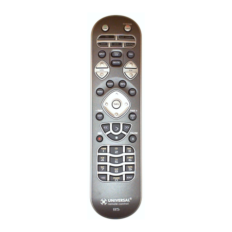
The Radio remote-control manages the functioning of the stove/boiler and monitors the state of operation in
real time. The main characteristics are:
Remote Control of the system with battery supply
Room Thermostat embedded
Parameters management of the control board
Warnings:
The system works on the radio band ISM 433,92MHz. The transmission and receiving distance can be
reduced in case of a noisy environment: other devices as wireless headphones, video sender, toys or other
devices could influence in the performances of the system.
Check the presence of such instruments and make sure to turn them off in order to avoid electromagnetic
waves pollution.
If more remote controls are nearby, it is necessary to associate the remote control with a specific
stove/boiler (see section 3, Settings Menu).

Pag. 4 / 9DMAN63W0000020-2Ways2 Manual - System100 Hydro STD2
2Control Panel
2.1 The Keys
Key
Function
Description
On/Off
Ignition and Extinguishing of the boiler/stove by pushing the button for
3 seconds
Unlock
System Unlock by pushing the key for 3 seconds
ESC
Esc
Menu exit function
SET
Set
Enter in Submenu, modify and save data
Thermostat Modify
Radio Room Thermostat modification
Scroll Menu and
Submenu
Scroll Submenu and Menu
Sleeping Mode
By pushing the button when the display is on the main frame, the
remote control will continue to work, but the display will switch off. To
switch on the display push the button again.
Standby Mode
By pushing the button for 3 seconds when the main frame is displayed
,it is possible to switch off completely the remote control and thus
reduce the battery consumption. This feature is to be used in case of
prolonged non-use of remote control. If the function is activated, the
system uses the room probe connected to the Controller.
To switch on the remote control push the button twice.
2.2 The Display
Pushing the button the display turns on and the main frame appears.
-Errors:
Er01: Error Safety High Voltage 1. Also with the system Off.
Er02: Error Safety High Voltage 2. Only if the Combustion Fan is On.
Er03: Extinguishing for exhaust under temperature.
Er05: Extinguishing for exhaust over temperature.
Er06: Pellet Thermostat open (backfire in the brazier)
Er07: Encoder Error. No Encoder signal.
Er08: Encoder Error. Combustion Fan regulation failed.
Er11: Real time clock error, day and time not correct due to prolonged absence of power supply
Er12: Extinguishing for Ignition failed.
Er15: Lack of voltage supply.
Er17: Air Flow Regulator error.

Pag. 5 / 9DMAN63W0000020-2Ways2 Manual - System100 Hydro STD2
Er18: Run out of pellet
Er23: Boiler probe or Buffer probe open
Er25: Error Engine cleaning Brazier
Er39: Air Flow Regulator Sensor broken.
Er41: Minimum air flow in Check Up not reached.
Er42: Maximum air flow Up reached (F40).
Er44: Open door error.
Er47: Auger Encoder error, no Encoder signal.
Er48: Auger Encoder error: auger speed regulation failed.
Er52: I/O I2C Module error
Er57: Test ’Forced Draught High’ in Check Up fail (FL70)
Service: It notifies that the planned hours of functioning (parameter T66) is reached. It is necessary to
call for service.
-Other messages:
Prob: Visualization of the state of temperature probes. The message displayed in Check-Up indicates
that the red temperature on one or more probes is equal to the minimum value (0°C) or maximum (it
depends on probe considered). Check that the probes aren’t open (0°C) or in short-circuit (maximum
value of the temperature scale).
Clean: This message notifies that the planned hours of functioning (parameter T67) is reached. It is
necessary to clean the stove or boiler.
Block-Ignition: The message appears if the system is turned off during Ignition (after Preload) by an
external device: the system will stop only when it goes in Run Mode.
Door: The message notifies that the door is open.
Cleaning On: Periodic Cleaning in progress.
-Battery Charge Level:
Maximum battery charge
Battery discharged; replace the
battery as soon as possible. The
image blinks.
Battery charge at 2/3
Battery charge at a 1/3
3The Menu
To enter the Menu press the SET key on the remote control. The Submenu list or the parameter list will
appear with the current set value:
The storage of a new value is associated to the transmission to the control board; if it fails the message
'Transfer not successful '
appears.
In this case try to modify again the parameter’s value.
Auger
C01 1.0_________
C02 1.2
C03 4.1
C04 5.6
C05 6.2
C05 7.4
C05 7.4
System Menu
Auger____________
Combustion Fan
Combustion Fan 2
Heating Fan
Thermostats
Timers
Auger
C01
Max: 60.0
Set: 1.0
Min: 0.0
Submenu
Parameter Code
Maximum Value
Current Value
Minimum Value

Pag. 6 / 9DMAN63W0000020-2Ways2 Manual - System100 Hydro STD2
3.1 Main Thermostat Modification
Use the buttons to change the Radio
Room Thermostat value (it is possible only if it
has not been disabled in the specific Menu).
The value can be modified using the same
buttons, save data occurs automatically at the exit
of Menu or pushing SET key.
3.2 User Menu
MENU
DESCRIPTION
Combustion
Management
Power
It allows to modify the combustion power of the system in Pellet mode. It can be set
in automatic or manual mode. In the first case, the system chooses the combustion
power. In the second case, the user selects the desired power. On the left side of the
display is signalled the combustion modality (
A
=automatic combustion,
M
=manual
combustion) and the working power level of the system.
Recipe
Menu to select the combustion recipe. The maximum value is the number of recipes
visible to the user (parameter P04). If P04=1 the Menu is not visible.
Auger Calibration
It allows to modify the default value of the Auger’s speed and On Times. The values
are in the range –7 ÷ 7. The default value is 0.
Fan Calibration
It allows to modify the default value of the Combustion Fan speed. The values are in
the range –7 ÷ 7. The default value is 0.
Heating
Management
Boiler Thermostat
It allows to modify the value of the Boiler Thermostat. You can choose the minimum
and maximum values by setting the corresponding thermostats T26 and T27.
Buffer tank Thermostat
It allows to modify the value of the Buffer tank Thermostat. It will be visible only if
you select a plumbing plant including a Buffer Probe (P26=2, 3, 4).
Heating Power
It allows to change the power of the fan heating. This menu is visible only by setting
an output configurable to 6 and A04=0. You can set the management of the heating
system in automatic or manual mode.
Heating
Description
0FF
Heating fan is stopped (it is possible only if P95=0)
1–Power user
number
Power is adjusted manually from 1 to the maximum number of
power user (parameter P03)
Auto
Power is adjusted automatically according to the value of the
parameter P06
Stove Room Thermostat
It allows to modify the value of the Local Room Thermostat. It is visible only if a
configurable input is set as Room Probe.
Summer-Winter
The user may select between Summer-Winter mode.
Chrono
Menu to select the Chrono Program modality and to set the time of
Ignition/Extinguishing of the boiler/stove.
For more details please see section 3.2.1.
Monitor
This Menu shows some System data of interest
Display
Description
Exhaust T.
Exhaust temperature [°C]
Termostato
Ambiente Radio
Set: 20°C

Pag. 7 / 9DMAN63W0000020-2Ways2 Manual - System100 Hydro STD2
Stove Room T.
Room Temperature detected by the board [°C] (visible only if
an input is set as Room Probe)
Buffer T.
Buffer tank Temperature [°C] (visible only if P26=2, 3, 4)
Pressure
Water Pressure [mbar]
Air Flow
Air Flow [cm/s]
Fan
Combustion Fan speed [RPM] (visible only if P25=1, 2)
Auger
Auger working time [s] (visible only if P81=0)
Recipe
Current combustion recipe [nr] (visible only if P04>1)
Product Code
Product Code: 537
FSYSI01000060.0.0
Control board firmware code and version
FSYSC02000032.0.0
Remote Control firmware code and version
Manual Load
The procedure activates the pellet manual loading with activation in continuous
modality of the Auger motor. The loading stops automatically after 600 seconds. The
system must be OFF for the function can be activated
Cleaning Reset
Menu to reset the ‘System Maintenance 2’ function. It is visible only if T67>0.
Settings
Thermostat Management
Menu to set the Radio Room thermostat functioning.
Thermostat Status
Description
Enabled
The Radio Room Thermostat is used by the system
Disabled
The system uses the thermostats of the control panel and, on
the main frame of the display, the value and the image of the
thermostat will disappear.
Radio Standby
Menu to completely switch off the remote control and lower the battery consumption
Description
Display
Push the SET button to enable the Standby mode. To
turn on the radio again, first push the key and then
the button twice.
If the function is activated, the system uses the room
probe connected to the control board.
This feature is to be used in case of prolonged non-use
of the radio terminal.
Time and Date
Menu to set time and date.
Description
Keys
Display
Select hours, minutes, year, month and day
Enter editing
SET
Modify the value
Save
SET
Exit
ESC
Radio Test
This Menu is used to test the connection between the radio terminal and the control
board, thereby verifying the level of the electromagnetic pollution. The Terminal
Radio enters in continuous transmission and counts the correct and failed answers.
The quality of the signal depends on the number of the errors.
Change Code
Code changing allows matching the remote control with a specific board, so that a
remote control is matched only with a specific stove or boiler (thus permitting the
coexistence of different systems in the same area). In order to change the code:
select a code
enter the Learn Menu of the control board and push the set key
push the SET button on the terminal radio and verify the result of the
operation
Contrast Setting
This Menu allows setting the display contrast
Description
Keys
Display
Modify the value
Set Contrast
+
15
-
Time and Date
16:45
Thursday
07/02/2016
Standby
Radio
Enable _____

Pag. 8 / 9DMAN63W0000020-2Ways2 Manual - System100 Hydro STD2
Save
SET
Exit
ESC
Key Tone
Menu to enable or disable the key tone.
Language Selection
Menu to change the language. The highlighted language is the one currently set.
System Menu
Menu to enter in the Technical Menu.
It is protected by password: the default password is 0000.
Push SET to enter in editing mode, and to increase or decrease the selected
digit. Push SET to save the digit and pass to the next. Push ESC to cancel the digit
or exit from Menu. If the password is right, the first menu screen appears.
Menu
Description
Auger
Auger Menu
Combustion Fan
Combustion Fan Menu
Exhaust Fan 2
Exhaust Fan 2 Menu
Heating Fan
Heating Fan Menu
Thermostats
Thermostats Menu
Extinguishing Th
Extinguishing Thermostats Menu
Timers
Timers Menu
Enables
Enables Menu
Air Flow Sensor
Primary Air Regulator Menu
Counters
Counters Menu
Outputs’ Test
Outputs’ Test Menu
Restore Default Value
Menu to restore the parameters’ values set by the
manufacturer
3.2.1 Chrono Menu
Menu to set the system ignition/extinguishing times.
3.2.1.1. Chrono Modality
To turn on the system by chrono, select the modality after the programming the ignition/extinguishing times
Description
Keys
Display
The current modality is highlighted and blinks
Select the favourite modality
Cancel the changes and restore the old modality
ESC
Save the new setting
SET
Exit from Menu
ESC
3.2.1.2. Chrono Programming
Choose the type of programming to set (after making the programming it is necessary to select the desired
mode from the Modality Menu to turn on/off the system by Chrono):
Daily:
Select the day of week and program the system ignition/extinguishing times; for each day there
are 3 time slots.
Daily
Monday___________
Tuesday
Wednesday
Thursday
Friday
Saturday
Venerdì
Programming
Daily________
Weekly
Week-End
Daily
Monday
ON OFF
09:30 11:15
00:00 00:00
00:00 00:00
Modality
Chrono Modality
Disable
Daily
Weekly
Week-End

Pag. 9 / 9DMAN63W0000020-2Ways2 Manual - System100 Hydro STD2
Program across midnight
Set the hour of extinguishing of a day at 23:59 and set the hour of ignition for the next day at 00:00.
Weekly:
Program the times to switch on and off the system (there are 3 time slots).
Week-End:
Choose between 'Monday-Friday' and 'Saturday-Sunday'. There are 3 time slots for each
period.
The three types of programming are stored separately: if for example the Daily modality is set, the other
modalities are not changed.
Program Chrono
Keys
After choosing the favourite program:
Select the programming time
Enter in modify mode (the selected time blinks)
SET
Modify the timers
Save program
SET
Enable a program ( appears) or disable it ( appears)
Exit
ESC
Week-End
Mon-Fri__________
Sat-Sun
Programming
Daily
Weekly
Week-End
Week-End
Mon-Fri
ON OFF
09:30 11:15
00:00 00:00
00:00 00:00
Programming
Daily
Weekly
Week-End
Weekly
Mon-Sun
ON OFF
09:30 11:15
00:00 00:00
00:00 00:00
Table of contents
Other TiEmme Remote Control manuals
Popular Remote Control manuals by other brands
Tele Radio
Tele Radio Tiger T2 installation instructions

Radio Shack
Radio Shack Wireless Security Keychain Remote owner's manual
Hitachi
Hitachi PC-ARFPE Installation and operation manual
RIB
RIB SUN?CLONE ACG6058 quick start guide
SkylinkHome
SkylinkHome TD-318 User instructions

Biamp
Biamp IWA250 installation guide
