Tietzsch VARIOSAFE EXM 25 User manual

Rudolph Tietzsch GmbH & Co. KG
Willringhauser Straße 18
D-58256 Ennepetal
Telefon +49 2333-75989
Telefax +49 2333-75257
E-Mail: [email protected]
www.tietzsch.de EXM_BA_12-10
User Instructions
VarioSafe EXM 25
Symbols on the instrument
Attention! Observe user instructions!
EC-conformity
16
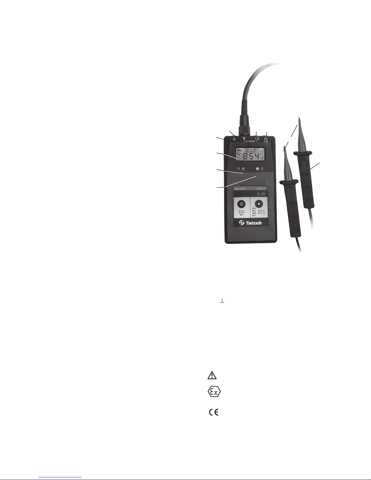
1 Test electrodes of voltage measuring line
(red conductor + /black conductor -)
2 Button DATA-HOLD
3 LED Ω (green): 0 ... 10 kΩ
4 LED Volt (red): 12 - 1000 V
5 LCD display
6 -socket, black standard socket
7 7-pin universal connector for voltage meauring
lines, temperature transmitter, clamp-on
ammeter and power supply unit
8 Ω-socket, red standard socket for resistance
measurements
9 A-socket, blue standard socket
fuse socket for current measurements
1
4
3
5
7 8 9
6
2
Ex marking:
Approved for potentially explosive atmospheres
in accordance with ATEX (EN 60079-0 and EN
60079-11) see sectionl 5.1

17
1. Application
The VarioSafe EXM 25 is an intrinsically safe multime-
ter which can be used in areas with a potentionally
explosive atmosphere in accordance with ATEX (EN
60079-0 and EN 60079-11) and EN/IEC 61010 for vol-
tage, resistance, current, frequency measurements
with measurement accessories for measurement of
temperature and high current.
2. Safety Precautions
When used for its intended purpose, safety of the
operator, as well as that of the instrument, is assured.
The voltage measurement tips contain moulded
multipliers within both test prods. They are extreme-
ly safe and comply with overvoltage category CAT IV.
In order to maintain awless technical safety condi-
tions, and to assure safe use, it is imperative that you
read these operating instructions thoroughly and
carefully before placing your instrument into service,
and that you follow all instructions contained
therein.
†
The device may only be used in the designated
Ex zones (section 5.1) and inside of the safety-
related limit values (section 5.2).
†
Before starting resistance measurements make
sure that the test object is at zero-potential.
†
Perform zero-potential tests at most up to the
following voltages:
Ex-class II up to 690 V, Ex-class I up to 1000 V and
with measurement tip 72011 up to 2000V.
†
Before putting into operation for the rst time and
at every day of use the VarioSafe EXM 25 has to be
checked at a known voltage source - e.g. a 230 V
socket to ensure that it works properly and
faultlessly (see display test and self test). If
indication of one or several systems fail in the
course of performing the self test according to
section 3, if function standby is not indicated or if
the device is damaged, the VarioSafe EXM 25 must
not be used again.
†
Maintainance is only allowed by the manufacturer
or explicitly authorised repair shops
(see section 7).
†
The measurement tips with extended (12 mm)
not insulated test electrodes are designed for use
at untouchable machinery materials. You may use
the extentions in EX-areas only when an uninten-
tional connection between conductive parts
(e.g. by short-circuit between test electrodes) can
denitely be excluded.

18
3. Putting into operation
3.1 Battery
Your instrument is already supplied with an energie-
block. Solely use the following energyblocks:
NiMH accumulator for class I and II T4:
type EXM 72025 (rechargeable)
Lithium battery for class I and II T6:
type EXM 72026 Li/T6
Attention!
Please observe section 6 before initial startup or
after your device has been in storage for a long
period of time.
3.2 Testing display and function
At every day of use the VarioSafe EXM 25 has to
be checked to ensure that it works properly and
faultlessly.
Self test 1 (Display test):
Press and hold button „ON/OFF“.All display seg-
ments light up on the display, additionally the V-LED
and the Ω-LED light up. When you release button
„ON/OFF“, the value 000 ... 001 V is indicated on the
display.
Self test 2 (Voltage measuring line):
Connect and lock the voltage measurement tips
type 72010/11 to the 7-pin universal connector.
Switch-on the device. Display: 000..001 V, in the
upper display line 1000 or 2000V. Put the test
electrodes, one after another, inclined 5 mm into the
W-socket.
Display shows‘Test’ and ‘rdy’ and green LED lights
up.
Note! In case the display continues showing 000 V
the measurement tip is damaged, please exchange.
Self test 3 (Voltage indication):
Check functions at a known voltage source - e.g. a
230 V socket.
Self test 4 (Resistance measurement):
Put the standard test lines into the Ω- and -socket.
Adjust the device to Ω, display: OL kΩ, hold test
prods together, display indication needs to be about
0.0 Ω and the green LED needs to light up.
Attention!
If indication of one or several systems fail in the
course of performing the self test, if function stand-
by is not indicated or if the device is damaged, the
VarioSafe must not be used again.

19
4. Measuring and testing
4.1. General information
The upper display line
shows currently selected
measurement range.
When this indication
is ashing you have to
connect special accesso-
ries e.g. TMZ clamp-on
ammeter.
The lower display line
shows the actual
metered value.
The instrument is switched o automatically
approximately 60 seconds after the last
measurement in order to extend battery life. In the
display the indication„o“ appears (exception: see
frequency measurements). The backlight turns o
when no measurement result is applied or when the
battery is low.
With the ON/OFF button engaging the
VarioSafe EXM 25 to voltage, call the
display test and switch-o the device.
With the function button you can select
the designated measurement range:
Function upper
display line
Voltage with tip EXM 72010 1000 V
Voltage with tip EXM 72011 2000 V
Voltage, automatic range mV, V AuTo
resistance
Ω
current I
current
with clamp-on ammeter
I ashes*
frequency FrE
temperature with TMZ T ashes*
* When the measurement ranges are indicated by a
ashing symbol the connection of special
accessories is necessary, e.g. a clamp-on ammeter or
the temperature transmitter
leading sign
battery status (see section 6)
►

4.2 Testing voltage and polarity
Attention!
Connect the voltage measurement tips to the
7-pin universal connector only when the device is
switched-o. Switch-on the device not until they are
locked and select rang if necessary.
Note!
If Hold appears permanently, probably the 7 kV tip
has been attached when the device was switched-
on. Put both test prods with safe contact onto the
metering point and the voltage value is indicated
in the lower display line. At a voltage of 12 V ashes
the red LED and button functions are locked.
Note!
Because of integrated multipliers the device indi-
cates few mV while in open-circuit operation, this
has no inuence on the result of measurement.
1000 / 2000 V voltage range (1000 V) / (2000 V)
The voltage range adjusts automatically to the used
DATA-HOLD measurement tip type 72010 or 72011.
The measurement range serves for a fast detection
of measurement values between 0 – 1000 / 2000 V
without decimal places.
The display range of the VarioSafe EXM 25 extends
to 1150 V AC / 1600 V DC with 72010 and 2 kV with
72011. Observe the safety precautions (see section
2) for Ex-areas.
Indication of polarity
Type of voltage is indicated by the symbols
~ and – . Direct voltage: is minus applied to the test
prod with Hold button, the leading sign„-“ appears,
is plus applied no leading sign appears in front of
the indicated value.
HOLD function
The maximum voltage value can be„stored“ on the
display when activated the button„HOLD“. The value
is recorded for approx. 30 seconds or until you press
button„HOLD“ again. The Hold-function is stopped
when again a voltage is impressed.
Note! When the measured value does not vary for
2 sec, then the maximum value is recorded.
20

Automatic voltage range (AuTo)
The voltage range adjusts automatically to the used
voltage measurement tip type 72010 or 72011.
The measurement range serves for a fast detection
of measurement values between 1 mV – 1000 /
2000 V, the optimal measurement range is selected
automatically.
4.3 Resistance measurements (Ω)
Before taking any resistance measurements always
check that the test object is at zero-potential.
Connect 4 mm standard test lines to the Ω- and
-socket. Adjust the device to Ω. Ohm is indicated in
the upper display line.
Note!
The arrow signalizes „out of measurement range“.
The measurement range serves for a denite
determination of impedances of 0,1 Ω – 20 MΩ.
A selection between Ω-, kΩ- and MΩ ranges occurs
automatically after applying to the impedance.
The green LED signalises resistance values that a
lower than 10 kΩ.
4.4 Current measurement (I)
Attention!
You may perform current measurement in Ex-areas
only in measuring circuits with peak values of
maximum 50 V.
You may only measure currents up to maximum 2 A.
Connect 4 mm standard test lines to the A- and
-socket.
The measurement range serves for measuring
AC/DC currents in the range of 1 mA – 2 A.
A selection between mA and A occurs automatically
after attaching the test prods.
The moulded fuse activates with currents of more
than 2 A.
The fuse can only be changed by the manufacturer
(Service section 7).
4.5 Current measurement with clamp-on ammeter
MZ 1005 (ashes)
Measurements with MZ 1005 are only permissible
in Ex I-areas.
Please observe the separate user instructions of the
clamp-on ammeter MZ 1005. Connect the MZ 1005
to the 7-pin universal connector.
Within the clamp-on ammeter range you can mea-
sure AC/DC currents between 0,1 and 1000 A, the
optimal measurement range is selected automati-
cally.
21

22
4.6 Frequency measurements (FrE)
Connect the voltage measurement tip type 72010 to
the 7-pin universal connector.
The measurement range serves for measurements of
frequencies in the range of 0,1 Hz – 10 kHz with
voltages > 5 V. A selection between Hz and kHz
occurs automatically after attaching the test prods.
Note!
While the device is in open-circuit operation the
display may show 0,00 Hz/kHz ±1 digit.
With low frequencies the measurement signal needs
to be placed for a few seconds before it indicates a
reliable value.
The automatic shout-down can be deactivated by
interfering signals, e.g. because of low frequencies
with attached measurement tips.
4.7 Temperature measurements with TMZ 25
(T ashes)
Measurements with the intrinsically safe TMZ 25 and
a Fe-CuNi-sensor are only permissible in Ex I- and Ex
II-areas. Connect the TMZ 25 to the 7-pin universal
connector and plug temperature sensor on the TMZ
until it’s catched.
With the TMZ 25 you can measure temperatures bet-
ween – 80 and + 600 °C. The optimal measurement
range is selected automatically.
Note!
With the universal sensor indication on the display is
rst readable after approx. 30 s, with surface sensors
after approx. 10 s. Special sensors can be delivered.

23
5. Characteristic Values:
5.1 Identication marking / Ex zones
EC-Type Examination Certicate
DMT 03 ATEX E 013
II 2G Ex ib IIC T4/T6
I M2 Ex ib I
5.2 Safety-related limit values
Intrinsically electric circuits
Voltage (by 50 V tip) 2 A
Internal inductance Li < 5 μH
Voltage with measurement tips:
Type EXM 72010, 72011, 72012
Class IIC AC/DC ≤ 690 V with tip 72010
Class IIB AC/DC ≤ 690 V with tip 72010
Class I AC/DC ≤ 1000 V with tip 72010
Class I AC/DC ≤ 2000 V with tip 72011
Resistance ranges maximum values in case of fault:
Voltage 3,6 V
Current 4 mA
Maximum permissible external
capacitance/inductance:
Class IIC 200 mF/1000mH
Class IIB 3000 mF/1000mH
Class I 3000 mF/1000mH
Frequency 2 up to 10 kHz
Current (up to 50 Vpeak) 2 A
internal inductance Li < 5 μH
Energie source (moulded design):
NiMH accumulator
Type EXM 72025/T4
Nominal voltage DC 8,4 V
Maximum voltage U011,2 V
Temperature range T4
Lithium battery
Type EXM 72026 Li/T6
Nominal voltage DC 3,6 V
Maximum voltage U03,9 V
Temperature range T6
Temperature with TMZ 25:
-80°C <TA< +600°C
Curent with clamp-on ammeter type MZ 1005:
(solely for class I)
AC/DC 1000 A
Frequency up to 500 Hz

24
5.3 Technical data
Digital display:
Type 7-segment-gures,
2 lines, backlight
Display range 0 ... 1999 digit
Bleeder indication „OL“ indicated
Electromagnetic compatibility
EMV requirements DIN-EN 61326
Ambient conditions
Operating temperature -10 ... + 40°C
Mechanical construction
Casing impact resistant antistatic
plastic housing (R < 109Ω ) with
unbreakable display cover
Protection
category IP 54
Circuit points 3 standard jacks, thereof
1 fuse socket
7-pin universal connector
Weights approx. 350 g (incl. battery)
Measurement ranges
automatic range connection
1000 V AC/DC with 72010, xed range
2000 V AC/DC with 72011, xed range
Auto- range (solely 72010/11)
AC 10, 100, 1000 V (1150 V) TRMS up to 500 Hz
DC 1, 10, 100, 1000 V (1600 V)
200, 2000 Ω (diode test) 20, 200 kΩ, 2 MΩ
20 MΩ
AC/DC 1000 mA, 2 A
(solely with clamp-on ammeter)
AC/DC 100, 1000 A
200, 2000 Hz,
10 kHz, with voltage measurement tip 72010
(solely with TMZ) 150 °C
600 °C
Resolution
1 V
0,01 ... 1 V
0,001 ... 1 V
0,1... 1000 Ω
10k Ω
1 ... 10 mA
0,1 ... 1 A
0,1 ... 1 Hz
0,01 kHz
0,1 °C
1 °C
Limiting deviation
at +10...30°C
±1% +2 digit
±2,5% +5 digit
AC ±1% +2 digit
DC ±0,5% +2 digit
±1% +5 digit±
5% +10 digit
±1% +2 digit
±1,5% +2 / 3digit
±1% +2 digit±
3% +2 digit
±1,5% +3 digit±
1,5% +2 digit
On/O-button / Display test
Function taster
Function returns to the 1000 V (2000 V) -range, see above
25
6. Maintainance
The EXM is completely maintainance-free except for
ist own energy source (see section 6.1). Nevertheless,
for safe operation observe the following information:
The VarioSafe is to be stored in a dry place.
The plastic housing can be cleaned with a cloth dam-
pened with alcohol (isopropyl) or soapy water.
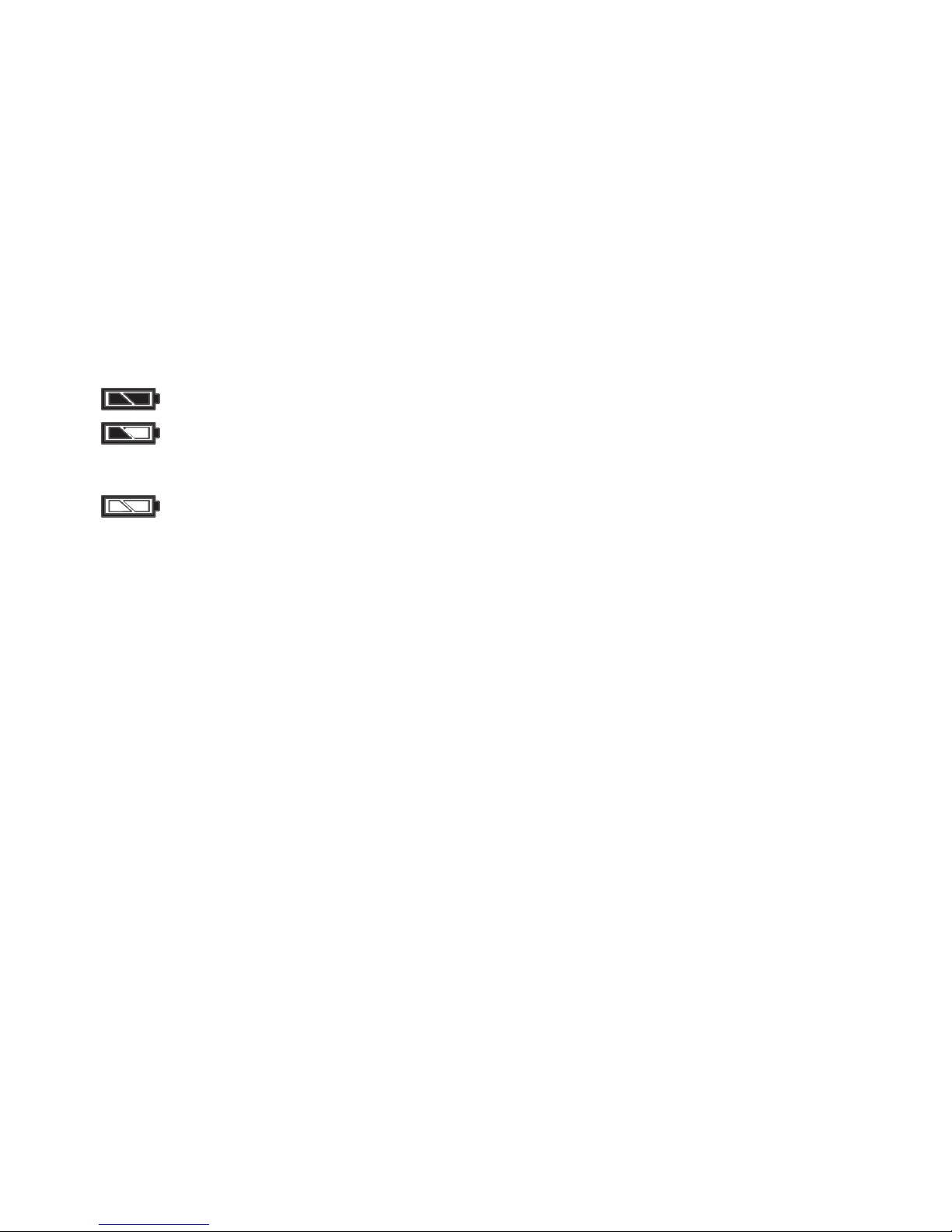
6.1 Battery status
The latest status of the battery or the accumulator is
symbolised by a 3 stage battery symbol in the display.
=
battery full
=
battery half-full.
Many measurements still
can be performed.
=
batterie empty.
The backlight deactivates
automatically.
Attention!
When the empty battery symbol ashes, taking
measurements is not possible anylonger. The battery
needs to be exchanged or the accumulator recharged
immediately.
6.2 Change battery
The change of battery is possible in Ex-areas.
Solely use the following energyblocks:
Lithium battery for class I and II T6:
type EXM 72026 Li/T6
NiMH accumulator for class I and II T4:
type EXM 72025/ T4 (rechargeble)

26
6.3 Recharge battery
Attention!
Recharge accumulators outside of Ex-areas.
Recharging occurs with the power supply unit NG4
without removing the accumulator from the EXM:
The NG4 is connected with the 7-pin universal
connector of the EXM and put into the 230 V/50 Hz
socket. Charging normally takes 14 hours.
Note!
Accumulators were only shortly charged by the
manufacturer, so that it’s necessary to perform a
charging (approx. 24 hours) before initial startup.
This applies as well to longer periods of storage
(more than 6 months). Full capacitance of NiMH
accumulators ist rst reached after 2 - 3 cycles of
charging and discharging.
For preservation of full capacitance the accumula-
tors should not be recharged until they are empty
(BAT symbol = maximum half box). The accumulator
suers damages with frequent supercharging.
6.4 Storage
The VarioSafe is to be stored in a dry place in tempe-
ratures of -20°C to +80°C. If the unit is to be stored
for a lengthy period of time the battery should be
removed and the unit packed in dust-tight packing.
7. Repair
Repairing is only allowed by the manufacturer or
explicitly authorised repair shops.
In case of damages at the VarioSafe EXM 25, in case
of failure of the function test according to section
3.2 or for a detailed inspection and calibration
please contact:
manufacturer (address see page 1) with a
description of failure.
27
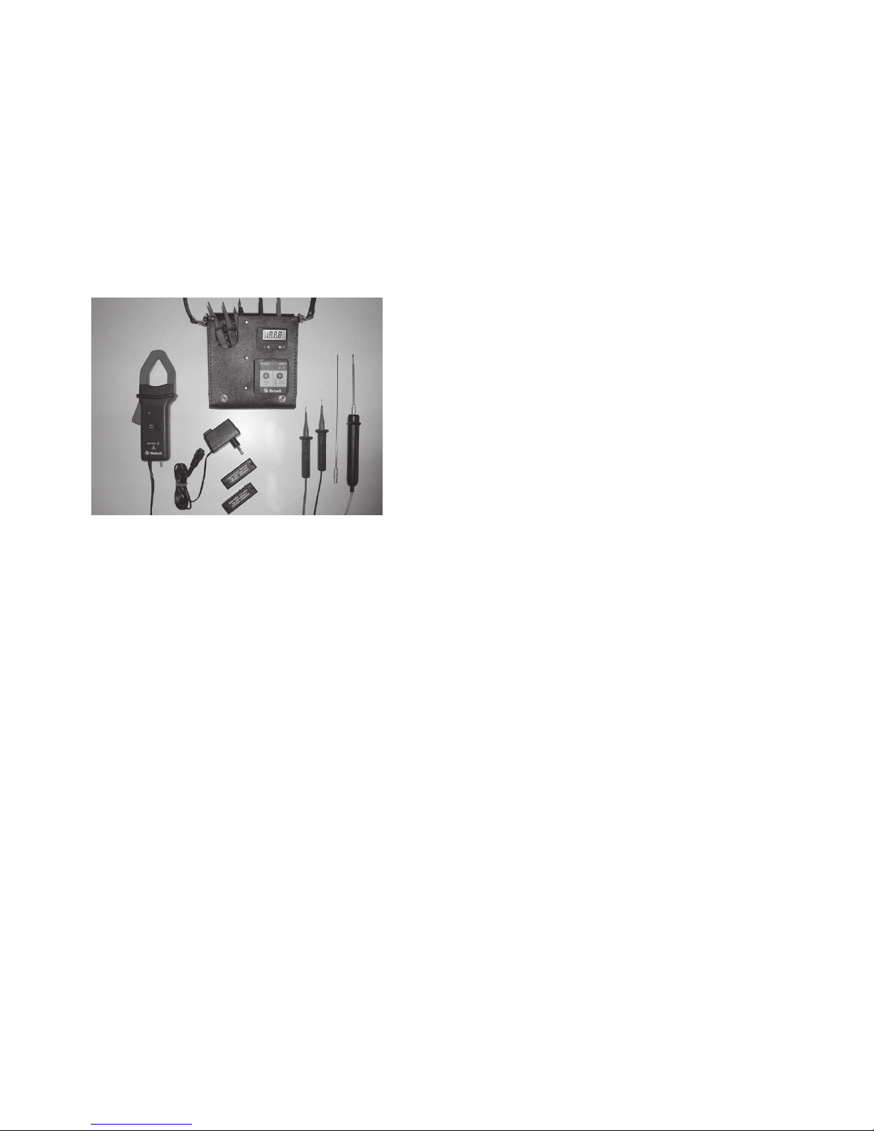
8. Accessories / Spares
Leather bag EXMLED:
The case for the EXM and the test cables is designed
in such a way that the unit does not have to be
taken out for measurements.
Using the additional lugs and push-buttons on the
shoulder strap and case the unit can be secured in a
comfortable position to facilitate readings.
Clamp-on ammeter MZ 1005
Clamp-on ammeter for current measurements of
0,1 – 1000 A in Ex – I areas.
Power supply unit NG64 for charging the
accumulator
NiMH accumulator AK72025/T4
Lithium battery LB 72026Li/T6
Temperature transmitter TMZ 25
For temperature measurements between – 80 and
+ 600 °C in Ex-I and Ex–II areas with universal sensor
EXMTFU or surface sensor EXMTFO
Voltage measurement tips
SPA up to 690 V Ex II and 1000 V Ex I:
voltage measurement tips with DATA-HOLD button
EXM 72010 standard with short test electrodes
EXM 72010-L with large test electrodes *
SPA HS2 up to 2000 V Ex I:
EXM 72011* HS- voltage measurement tips 2 kV
*Attention!
Please observe the particular security advice (see
section 2) for extended measurement tips (12 mm)
with not insulated test electrodes.

Quick user guide VarioSafe EXM 25
This quick user guide serves für a quick start. In regard
of your own safety please observe safety-related Ex-
characteristic values and for further information the
detailed user instructions.
On/O/test Select function
28
Attach tips or accessories
1
Switching-on and self-test
2
* When the measurement ranges are indicated by a ashing
symbol the connection of special accessories is necessary, e.g.
clamp-on ammeter or temperature transmitter.
The upper display
line shows currently
selected measurement
range.
The lower display
line shows the actual
metered value.
battery status
leading sign
Function upper
display line
Voltage with tip EXM 72010 1000 V
Voltage with tip EXM 72011 2000 V
Voltage, automatic range mV / V AuTo
resistance
Ω
current I
current
with clamp-on ammeter
I ashes*
frequency FrE
temperature with TMZ T ashes*
Select range/function
3
Voltage Resistance Current
Ex-Group 0,1Ω - 20 MΩ 1 mA - 2 A
IIC ≤ 690 V
IIB ≤ 690 V Attention: At first Attention: Up to
I ≤ 1000 V check voltage-free max. 50 V only!
Temperature with TMZ parts!
Current with MZ
Other manuals for VARIOSAFE EXM 25
1
Table of contents


