KYORITSU KEW SNAP Series KEW2040 User manual

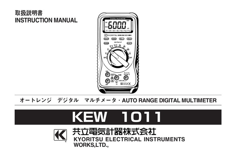
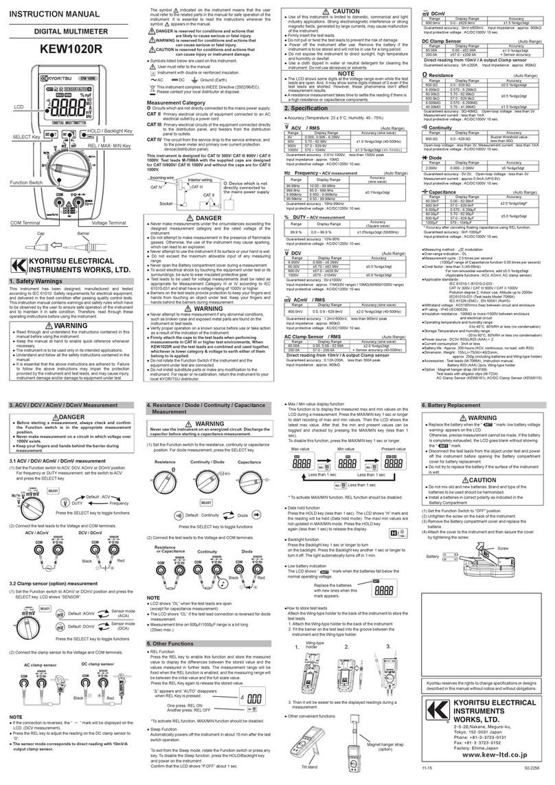
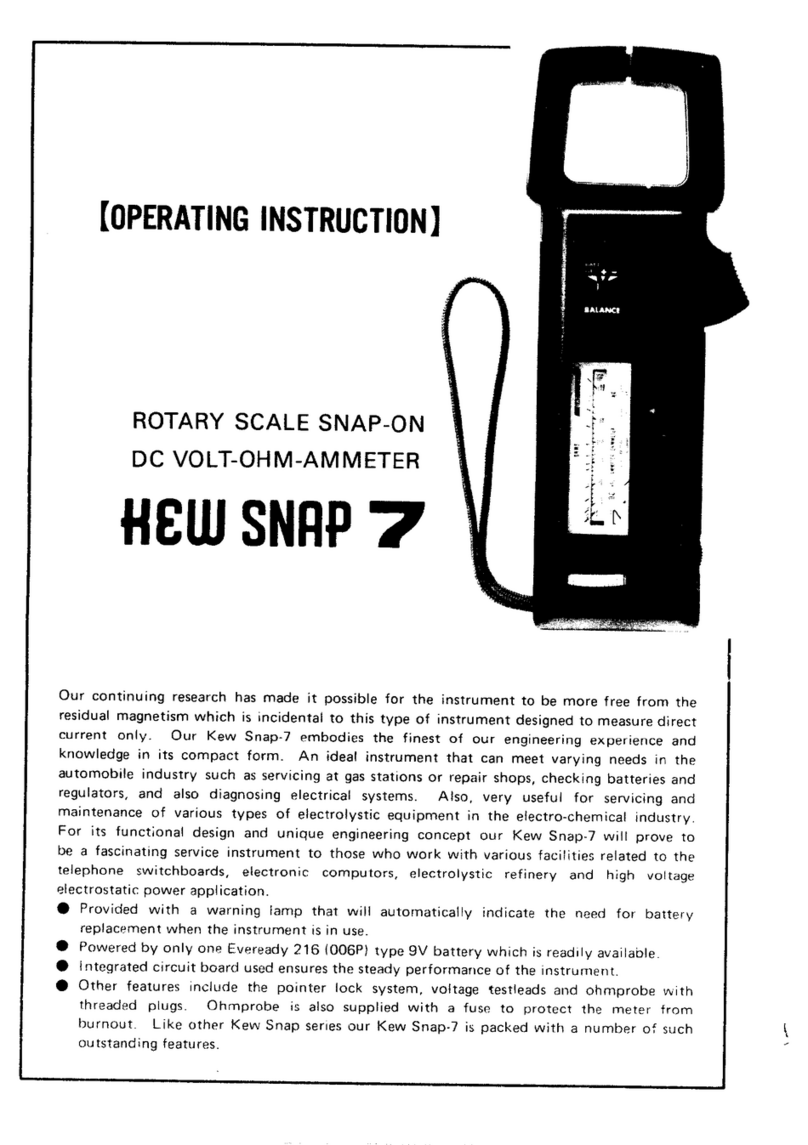
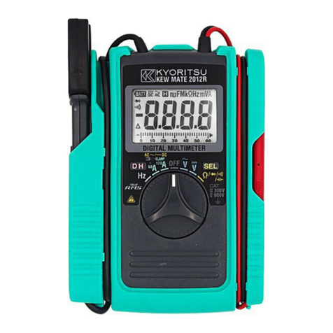
INSTRUCTIONMANUAL
DIGITALCLAMPMETER
KEWSNAP
SERIES
KEW2040
600AACOnlyType
KEW2055
1000AAC/DCType
1.Features
●
Designedtomeetinternationalsafetystandards.
IEC61010-1.IEC61010-031:2002&IEC61010-2-032
MeasurementCategory(CAT.)IV600V
PollutionDegree2
●
Double molded main body provides comfortable
singlehandedgrip
●
DataHoldFunction
●
LCD Backlight function to facilitate working at
dimlylitsituations.(KEW2055only)
●
RELfunctiontoindicatemeasurementvariation.
(Current,voltage,Resistancemeasurement)
●
MIN/MAX function enables easy reading of min &
maxvalueduringmeasurement.
●
WithContinuity&DiodeCheckFunction
●
NCV
(
Non Contact Voltage
)
Function for wiring
check.
●
600Vinputprotection.
●
Sleepfunctiontoextendbatterylife.
●
WithBarGraph,6039counts
2.SafetyWarnings
This instrument has been designed, manufactured and
testedaccordingtoIEC61010:Safetyrequirementsfor
ElectronicMeasuringapparatus,anddeliveredin
the best condition after passed the inspection. This
instructionmanualcontainswarningsandsafety
rules which must be observed by the user to ensure
safeoperation of the instrument and retainit in safe
condition.
Therefore, read through these operating instructions
beforeusingtheinstrument.
WARNING
●
Read through and understand the instructions
containedinthismanualbeforeusingthe
instrument.
●
Keep themanual athandto enablequick
referencewhenevernecessary.
●
Theinstrumentistobeusedonlyinitsintended
applications.
●
Understand andfollowallthesafety
instructionscontainedinthemanual.
●
It is essential that the above instructions are
adheredto.
●
Failure to follow the above instructions may
causeinjury,instrumentdamageand/ordamage
toequipmentundertest.
Thesymbol indicatedontheinstrumentmeansthat
theusermustrefertotherelatedpartsinthemanual
forsafeoperationoftheinstrument.Itisessential to
read the instructions wherever the symbol appears
inthemanual.
DANGERisreservedforconditionsandactions
thatarelikelytocauseseriousorfatalinjury.
WARNINGisreservedforconditionsandactions
thatcancauseseriousorfatalinjury.
CAUTIONisreservedforconditionsandactions
thatcancauseinjuryorinstrumentdamage.
●
Marks listed in the table below are used on this
instrument.
Usermustrefertothemanual.
Instrumentwithdoubleorreinforcedinsulation
Indicates that this instrument can clamp on
bare conductors when measuring a voltage
corresponding to the applicable measurement
category,whichismarkednexttothissymbol.
AC
DC
AC&DC
DANGER
●
Nevermakemeasurementonacircuitinwhich
voltageoverAC600Vexists.
●
Do not attempt to make measurement in the
presence of flammable gasses. Otherwise, the
useoftheinstrumentmaycausesparking,
whichcanleadtoanexplosion.
●
Transformerjaw tipsaredesignednotto short
the circuit under test. If equipment under test
has exposed conductive parts, however, extra
precaution should be taken to minimize the
possibilityofshorting.
●
Never attemptto usethe instrumentifits
surfaceoryourhandiswet.
●
Donotexceedthemaximumallowableinputof
anymeasuringrange.
●
Neveropen theBattery coverduringa
measurement.
●
Theinstrumentistobeusedonlyinitsintended
applications or conditions. Otherwise, safety
functions equipped with the instrument doesn
t
work,andinstrumentdamageorseriouspersonal
injurymaybecaused.
WARNING
●
Never attempt to make measurement if any
abnormal conditions, such as broken case
and exposed metal parts are found on the
instrument.
●
Do not rotate the Function Switch while the
testleadsarebeingconnected.
●
Do not install substitute parts or make any
modification to the instrument. For repair or
re-calibration, return the instrument to your
localdistributorfromwhereitwaspurchased.
●
Donottrytoreplacethebatteriesifthe
surfaceoftheinstrumentiswet.
●
Disconnect all the cords and cables from the
objectunder testandpowerofftheinstrument
before opening the Battery Cover for Battery
replacement.
●
Verify properoperation ona knownsource
before use or taking action as a result of the
indicationoftheinstrument.
●
Use appropriate personal protective equipment
suchasinsulatinggloves,Insulatingboots,and
safetyglasses.
CAUTION
●
Set theFunction Switchto anappropriate
positionbeforestartingmeasurement.
●
Firmlyinsertthetestleads.
●
Disconnect the test leads from the instrument
forcurrentmeasurement.
●
Donotexposetheinstrumenttothedirectsun,
hightemperatureandhumidityordewfall.
●
Altitude 2000m or less. Appropriate operating
temperatureiswithin0
℃
and40
℃
.
●
Thisinstrumentisn
tdust&waterproofed.Keep
awayfromdustandwater.
●
Be sure to power off the instrument after use.
When the instrument will not be in use for a
longperiod, place it in storageafter removing
thebatteries.
●
Usea clothdipped inwateror neutral
detergent for cleaning the instrument. Do not
useabrasivesorsolvents.
Measurementcategories
(Over-voltagecategories)
To ensure safe operation of measuring instruments,
IEC61010establishessafetystandardsforvarious
electrical environments, categorized as CAT.I to
CAT.IV, and called measurement categories. Higher-
numbered categories correspond to electrical
environments with greater momentary energy,
so a measuring instrument designed for CAT.III
environments can endure greater momentary energy
thanonedesignedforCAT.II.
CA T.Ⅰ
:Secondaryelectrical circuitsconnectedtoan
ACelectricaloutletthroughatransformeror
similardevice.
CAT.Ⅱ
:Primary electrical circuits ofequipment
connected to an AC electrical outlet by a
powercord.
CA T.Ⅲ
:Primary electrical circuits of the equipment
connected directly to the distribution panel,
and feeders from the distribution panel to
outlets.
CAT.Ⅳ
:The circuitfromthe servicedrop tothe
service entrance, and to the power meter
and primary over current protection device
(distributionpanel).
3.Specification
3-1.Measuringrange&accuracy
(accuracyguaranteedat23
℃±
5
℃
.humidity45
〜
85%)
ACCurrent600A,1000AFunction
Function Measuring
Range
Accuracy
KEW2040 KEW2055
600A0-600.0A
±
1.5%rdg
±
5dgt
(50/60Hz)
±
3.5%rdg
±
8dgt
(40-400Hz)
±
1.5%rdg
±
5dgt
(50/60Hz)
±
3.5%rdg
±
8dgt
(40-400Hz)
1000A0-1000A
N/A
DCCurrent600A,1000AFunction
Function Measuring
Range
Accuracy
KEW2040 KEW2055
600A
0-600.0A
N/A
±
1.5%rdg
±
5dgt
1000A
0-1000A
N/A
ACVoltageFunction
(
Auto-ranging,Inputimpedance:approx.10M
Ω)
Range Measuring
Range
Accuracy
KEW2040 KEW2055
6/60/600V1-600.0V
±
1.3%rdg
±
4dgt(50/60Hz)
±
3.0%rdg
±
5dgt(40
〜
400Hz)
DCVoltageFunction
(
Auto-ranging,Inputimpedance:approx.10M
Ω)
Range Measuring
Range
Accuracy
KEW2040 KEW2055
600mV/6/
60/600V0-600.0V
±
1.0%rdg
±
3dgt
Resistance
(
Continuity/DiodeCheck
)
Function
Range Measuring
Range
Accuracy
KEW2040 KEW2055
600
Ω
/6k/
60k/600k
Ω
6M
Ω
0-6M
Ω
±
1.0%rdg
±
5dgt
60M
Ω
6.00M-
60.00M
Ω
±
5%rdg
±
8dgt
ContBuzzer 0-600.0
Ω
Thresholdvalue:60
Ω±
30
Ω
Diode
Testvoltage:0-2V
Frequency/ DUTY Function
(
Auto-ranging for
Frequency
)
Range Measuring
Range
Accuracy
KEW2040 KEW2055
ACA 40Hz
−
400Hz
±
0.5%rdg
±
5dgt
ACV 1Hz
〜
10kHz
0.1-99.9%
(Pulsewidth/Pulseperiod)
±
2.5%rdg
±
5dgt
Note:Measurableinputsare:40Vrms@ACVor
60Arms@AC600A,350A@AC1000ARange
3-2.GeneralSpecification
●
Modeofoperation
:
Δ
∑mode
●
Display
:max.6039counts
(Frequency:9999)&Bargraph
●
Over-range indication : "OL" displayed when exceeding
the measuring range. (except for AC/DCV and 1000A
Function)
●
Rangeswitching :
Auto-ranging/Voltage,ResistanceRange
Singlerange/Continuity,Diodecheckand
DUTY
●
Samplerate
:threetimespersecond
●
Functionalconstruction:
OFF/ACA/ACV/DCV/
Ω
KEW2040
OFF/ACA/DCA/ACV/DCV/
Ω
KEW2055
●
Keys :
SELECT(AC/DCswitching&/
Ω
/ / ),REL
Δ
,
Hz/DUTY,MIN/MAX,HOLD/BackLight(KEW2055)
●
Powersource :DC3V/R03(UM-4)x2pcs
●
Lowbatterywarning
:
" "markisdisplayedat
2.4V
±
0.15Vorless.
●
Temperature & humidity : 23
℃±
5
℃
, relative humidity
accuracyguaranteed85%orless(nocondensation)
●
Operatingtemperature:0
〜
40
℃
,relativehumidity
&humidityrange85%orless(nocondensation)
●
Storagetemperature :-20
〜
60
℃
,relativehumidity
&humidityrange85%orless(nocondensation)
●
Currentconsumption:approx.12mA
●
SleepFunction:Automaticallypoweredoffinabout
15minafterthelastFunctionswitchoperation.
Press any key or rotate the Function Switch from
OFFtoanypositiontoexitfromtheSleepstate.
●
ApplicableStandards
IEC61010-1:2001
MeasurementCAT.IV600VPollutiondegree2
IEC61010-031:2002,IEC61010-2-032
EMC
:
EN61326
・
EN55022
・
EN61000-4-2(performancecriterionB)
・
EN61000-4-3(performancecriterionB)
●
OverloadProtection
CurrentRange :720AAC/10sec@KEW2040
1200AAC/DC/10sec@KEW2055
VoltageRange :720VAC/DC/10sec
ResistanceRange :600VAC/DC/10sec
●
WithstandVoltage
6880VAC
(
TRMS50/60Hz
)
/5sec
(betweenJawsandelectricalcircuit/betweeninternal
circuitandenclosure)
●
InsulationResistance:10M
Ω
ormore/1000V
(
betweenelectricalcircuitandenclosure
)
●
Conductorsize
KEW2040:approx.33mm
KEW2055:approx.40mm
●
Dimension
approx.254(L)
×
82(W)
×
36(D)mm/KEW2055
approx.243(L)
×
77(W)
×
36(D)mm/KEW2040
●
Weight:approx.:300g@KEW2040
:310g@KEW2055
●
Accessories
TestLeads Model7066/1set
BatteryR03
(
UM-4
)
/2pcs
InstructionmanualEnglish,Japanese/1pce
CarriyngCaseModel9094/1pcs
3-3.FunctionKeys
The"
●
"markshowsavailablefunctionateachRange.
DCCurrentMeasurement(KEW2055only)
HOLD SELECT ZERO Hz/
DUTY MAX/
MIN
ACA
● ● ● ● ●
ACV
●
-
● ● ●
DCA
● ● ●
-
●
DCV
●
-
●
-
●
Ω ● ● ●
-
●
-
●
- - -
-
●
- - -
4.Preparationformeasurement
4-1.CheckingBatteryVoltage
Set the Function Switch to any position other than
"
OFF
".When the displayisclearwithout "
BATT
" mark,
showing, battery voltage is enough. When the display
is blank or
"
BATT
" mark is indicated, replace the
batteriesaccordingtoSection7,BatteryReplacement.
CAUTION
The Sleep feature automatically powers the
instrument off in about 15 min after the last
switch or key operation. Therefore, the display
may be blank even with the Function Switch set
to a position other than "
OFF
". To operate the
instrument in this case, turn the switch back to
the "
OFF
" position, then to any other position,
orpressanykey.Replacethebatteriesifnothing
wasdisplayedafteraboveoperations.
4-2.CheckingSwitchSetting&Operation
Confirm the Function Switch is set to the correct
position, the instrument is set to the correct
measurementmode,
and the Data hold function is disabled. Otherwise,
desiredmeasurementcannotbemade.
5.Measurement
5-1.ACCurrentMeasurement
DANGER
●
Never make measurement on a circuit in which
voltage over AC600V exists to avoid getting
electricalshock.
●
Transformer jaw tips are designed not to short
the circuit under test. If equipment under test
has exposed conductive parts, however, extra
precaution should be taken to minimizethe
possibilityofshorting.
●
DonotmakemeasurementwiththeBattery
Coverremoved.
●
Disconnectthetestleadsfromtheinstrumentfor
currentmeasurement.
(1)Set theFunction Switchto"
600A
" or "
1000A
"
position.(onKEW2040,only"600A"isavailable)
AChasbeenselectedbydefault;presstheSELECT
key, when DC has been selected, to change it to
AC.ACmarkisdisplayedattheupperleftonthe
display.(KEW2055only)
(2)Press the trigger to open the transformer jaws
andclampthemontotheoneconductorundertest,
then take the reading on the display. Pressing the
"
Hz/DUTY
"Keyswitchestheindicationinfollowing
sequence.
ACCurrent
⇨
Hz
⇨
DUTY
Hz/DUTY
Function requires 60A or more at AC600A
Rangeand350AormoreatAC1000Arange.
CAUTION
●
MaxconductorsizeforKEW2040isapproxdia.
33mm and for KEW2055 is approx dia. 40mm.
During current measurement, keep the trans
former jaws fully closed. Other wise, accurate
measurementscannotbetaken.
5-2.DCCurrentMeasurement(KEW2055only)
DANGER
●
Nevermakemeasurementonacircuitinwhich
voltage over DC600V exists to avoid getting
electricalshock.
●
Do not make measurement with the Battery
Coverremoved.
(1)Set theFunction Switchto"
600A
" or "
1000A
"
position. AC has been selected by default; press
the SELECT key, when AC has been selected, to
changeittoDC.
DC mark is displayed atthe upperleft onthe
Transformer

INSTRUCTIONMANUAL
DIGITALCLAMPMETER
KEWSNAP
SERIES
KEW2040
600AACOnlyType
KEW2055
1000AAC/DCType
1.Features
●
Designedtomeetinternationalsafetystandards.
IEC61010-1.IEC61010-031:2002&IEC61010-2-032
MeasurementCategory(CAT.)IV600V
PollutionDegree2
●
Double molded main body provides comfortable
singlehandedgrip
●
DataHoldFunction
●
LCD Backlight function to facilitate working at
dimlylitsituations.(KEW2055only)
●
RELfunctiontoindicatemeasurementvariation.
(Current,voltage,Resistancemeasurement)
●
MIN/MAX function enables easy reading of min &
maxvalueduringmeasurement.
●
WithContinuity&DiodeCheckFunction
●
NCV
(
Non Contact Voltage
)
Function for wiring
check.
●
600Vinputprotection.
●
Sleepfunctiontoextendbatterylife.
●
WithBarGraph,6039counts
2.SafetyWarnings
This instrument has been designed, manufactured and
testedaccordingtoIEC61010:Safetyrequirementsfor
Electronic Measuring apparatus, anddeliveredin
the best condition after passed the inspection. This
instruction manual contains warnings and safety
rules which must be observed by the user to ensure
safeoperation of the instrument and retain it in safe
condition.
Therefore, read through these operating instructions
beforeusingtheinstrument.
WARNING
●
Read through and understand the instructions
contained in this manual before using the
instrument.
●
Keep themanual athandto enablequick
referencewhenevernecessary.
●
Theinstrumentistobeusedonlyinitsintended
applications.
●
Understand and follow allthesafety
instructionscontainedinthemanual.
●
It is essential that the above instructions are
adheredto.
●
Failure to follow the above instructions may
causeinjury,instrumentdamageand/ordamage
toequipmentundertest.
Thesymbol indicatedontheinstrumentmeansthat
theusermustrefertotherelatedpartsinthemanual
forsafeoperationoftheinstrument.It is essential to
read the instructions wherever the symbol appears
inthemanual.
DANGERisreservedforconditionsandactions
thatarelikelytocauseseriousorfatalinjury.
WARNINGisreservedforconditionsandactions
thatcancauseseriousorfatalinjury.
CAUTIONisreservedforconditionsandactions
thatcancauseinjuryorinstrumentdamage.
●
Marks listed in the table below are used on this
instrument.
Usermustrefertothemanual.
Instrumentwithdoubleorreinforcedinsulation
Indicates that this instrument can clamp on
bare conductors when measuring a voltage
corresponding to the applicable measurement
category,whichismarkednexttothissymbol.
AC
DC
AC&DC
DANGER
●
Nevermakemeasurementonacircuitinwhich
voltageoverAC600Vexists.
●
Do not attempt to make measurement in the
presence of flammable gasses. Otherwise, the
useoftheinstrumentmaycausesparking,
whichcanleadtoanexplosion.
●
Transformerjaw tipsaredesignednotto short
the circuit under test. If equipment under test
has exposed conductive parts, however, extra
precaution should be taken to minimize the
possibilityofshorting.
●
Never attemptto usethe instrumentifits
surfaceoryourhandiswet.
●
Donotexceedthemaximumallowableinputof
anymeasuringrange.
●
Neveropen theBattery coverduringa
measurement.
●
Theinstrumentistobeusedonlyinitsintended
applications or conditions. Otherwise, safety
functions equipped with the instrument doesn
t
work,andinstrumentdamageorseriouspersonal
injurymaybecaused.
WARNING
●
Never attempt to make measurement if any
abnormal conditions, such asbrokencase
and exposed metal parts are found on the
instrument.
●
Do not rotate the Function Switch while the
testleadsarebeingconnected.
●
Do not install substitute parts or make any
modification to the instrument. For repair or
re-calibration, return the instrument to your
localdistributorfromwhereitwaspurchased.
●
Do not try toreplacethebatteriesifthe
surfaceoftheinstrumentiswet.
●
Disconnect all the cords and cables from the
objectunder testandpowerofftheinstrument
before opening the Battery Cover for Battery
replacement.
●
Verifyproper operationon aknown source
before use or taking action as a result of the
indicationoftheinstrument.
●
Use appropriate personal protective equipment
suchasinsulatinggloves,Insulatingboots,and
safetyglasses.
CAUTION
●
Setthe FunctionSwitch toanappropriate
positionbeforestartingmeasurement.
●
Firmlyinsertthetestleads.
●
Disconnect the test leads from the instrument
forcurrentmeasurement.
●
Donotexposetheinstrumenttothedirectsun,
hightemperatureandhumidityordewfall.
●
Altitude 2000m or less. Appropriate operating
temperatureiswithin0
℃
and40
℃
.
●
Thisinstrumentisn
tdust&waterproofed.Keep
awayfromdustandwater.
●
Be sure to power off the instrument after use.
When the instrument will not be in use for a
longperiod, place it in storageafter removing
thebatteries.
●
Usea clothdipped inwateror neutral
detergent for cleaning the instrument. Do not
useabrasivesorsolvents.
Measurementcategories
(Over-voltagecategories)
To ensure safe operation of measuring instruments,
IEC61010establishessafetystandardsforvarious
electrical environments, categorized as CAT.I to
CAT.IV, and called measurement categories. Higher-
numbered categories correspond toelectrical
environments with greater momentaryenergy,
so a measuring instrumentdesignedforCAT.III
environments can endure greater momentary energy
thanonedesignedforCAT.II.
CA T.Ⅰ
:Secondaryelectrical circuitsconnectedtoan
ACelectricaloutletthroughatransformeror
similardevice.
CAT.Ⅱ
:Primary electricalcircuitsofequipment
connected to an AC electrical outlet by a
powercord.
CA T.Ⅲ
:Primary electrical circuits of the equipment
connected directly to the distribution panel,
and feeders from the distribution panel to
outlets.
CAT.Ⅳ
:The circuitfromthe servicedrop tothe
service entrance, and to the power meter
and primary over current protection device
(distributionpanel).
3.Specification
3-1.Measuringrange&accuracy
(accuracyguaranteedat23
℃±
5
℃
.humidity45
〜
85%)
ACCurrent600A,1000AFunction
Function Measuring
Range
Accuracy
KEW2040 KEW2055
600A0-600.0A
±
1.5%rdg
±
5dgt
(50/60Hz)
±
3.5%rdg
±
8dgt
(40-400Hz)
±
1.5%rdg
±
5dgt
(50/60Hz)
±
3.5%rdg
±
8dgt
(40-400Hz)
1000A0-1000A
N/A
DCCurrent600A,1000AFunction
Function Measuring
Range
Accuracy
KEW2040 KEW2055
600A
0-600.0A
N/A
±
1.5%rdg
±
5dgt
1000A
0-1000A
N/A
ACVoltageFunction
(
Auto-ranging,Inputimpedance:approx.10M
Ω)
Range Measuring
Range
Accuracy
KEW2040 KEW2055
6/60/600V1-600.0V
±
1.3%rdg
±
4dgt(50/60Hz)
±
3.0%rdg
±
5dgt(40
〜
400Hz)
DCVoltageFunction
(
Auto-ranging,Inputimpedance:approx.10M
Ω)
Range Measuring
Range
Accuracy
KEW2040 KEW2055
600mV/6/
60/600V0-600.0V
±
1.0%rdg
±
3dgt
Resistance
(
Continuity/DiodeCheck
)
Function
Range Measuring
Range
Accuracy
KEW2040 KEW2055
600
Ω
/6k/
60k/600k
Ω
6M
Ω
0-6M
Ω
±
1.0%rdg
±
5dgt
60M
Ω
6.00M-
60.00M
Ω
±
5%rdg
±
8dgt
ContBuzzer 0-600.0
Ω
Thresholdvalue:60
Ω±
30
Ω
Diode
Testvoltage:0-2V
Frequency/ DUTY Function
(
Auto-ranging for
Frequency
)
Range Measuring
Range
Accuracy
KEW2040 KEW2055
ACA 40Hz
−
400Hz
±
0.5%rdg
±
5dgt
ACV 1Hz
〜
10kHz
0.1-99.9%
(Pulsewidth/Pulseperiod)
±
2.5%rdg
±
5dgt
Note:Measurableinputsare:40Vrms@ACVor
60Arms@AC600A,350A@AC1000ARange
3-2.GeneralSpecification
●
Modeofoperation
:
Δ
∑mode
●
Display
:max.6039counts
(Frequency:9999)&Bargraph
●
Over-range indication : "OL" displayed when exceeding
the measuring range. (except for AC/DCV and 1000A
Function)
●
Rangeswitching :
Auto-ranging/Voltage,ResistanceRange
Singlerange/Continuity,Diodecheckand
DUTY
●
Samplerate
:threetimespersecond
●
Functionalconstruction:
OFF/ACA/ACV/DCV/
Ω
KEW2040
OFF/ACA/DCA/ACV/DCV/
Ω
KEW2055
●
Keys :
SELECT(AC/DCswitching&/
Ω
/ / ),REL
Δ
,
Hz/DUTY,MIN/MAX,HOLD/BackLight(KEW2055)
●
Powersource :DC3V/R03(UM-4)x2pcs
●
Lowbatterywarning
:
" "markisdisplayedat
2.4V
±
0.15Vorless.
●
Temperature & humidity : 23
℃±
5
℃
, relative humidity
accuracyguaranteed85%orless(nocondensation)
●
Operatingtemperature:0
〜
40
℃
,relativehumidity
&humidityrange85%orless(nocondensation)
●
Storagetemperature :-20
〜
60
℃
,relativehumidity
&humidityrange85%orless(nocondensation)
●
Currentconsumption:approx.12mA
●
SleepFunction:Automaticallypoweredoffinabout
15minafterthelastFunctionswitchoperation.
Press any key or rotate the Function Switch from
OFFtoanypositiontoexitfromtheSleepstate.
●
ApplicableStandards
IEC61010-1:2001
MeasurementCAT.IV600VPollutiondegree2
IEC61010-031:2002,IEC61010-2-032
EMC
:
EN61326
・
EN55022
・
EN61000-4-2(performancecriterionB)
・
EN61000-4-3(performancecriterionB)
●
OverloadProtection
CurrentRange :720AAC/10sec@KEW2040
1200AAC/DC/10sec@KEW2055
VoltageRange :720VAC/DC/10sec
ResistanceRange :600VAC/DC/10sec
●
WithstandVoltage
6880VAC
(
TRMS50/60Hz
)
/5sec
(betweenJawsandelectricalcircuit/betweeninternal
circuitandenclosure)
●
InsulationResistance:10M
Ω
ormore/1000V
(
betweenelectricalcircuitandenclosure
)
●
Conductorsize
KEW2040:approx.33mm
KEW2055:approx.40mm
●
Dimension
approx.254(L)
×
82(W)
×
36(D)mm/KEW2055
approx.243(L)
×
77(W)
×
36(D)mm/KEW2040
●
Weight:approx.:300g@KEW2040
:310g@KEW2055
●
Accessories
TestLeads Model7066/1set
BatteryR03
(
UM-4
)
/2pcs
InstructionmanualEnglish,Japanese/1pce
CarriyngCaseModel9094/1pcs
3-3.FunctionKeys
The"
●
"markshowsavailablefunctionateachRange.
DCCurrentMeasurement(KEW2055only)
HOLD SELECT ZERO Hz/
DUTY MAX/
MIN
ACA
● ● ● ● ●
ACV
●
-
● ● ●
DCA
● ● ●
-
●
DCV
●
-
●
-
●
Ω ● ● ●
-
●
-
●
- - -
-
●
- - -
4.Preparationformeasurement
4-1.CheckingBatteryVoltage
Set the Function Switch to any position other than
"
OFF
".Whenthedisplayisclear without "
BATT
"mark,
showing, battery voltage is enough. When the display
is blank or
"
BATT
" mark is indicated, replace the
batteriesaccordingtoSection7,BatteryReplacement.
CAUTION
The Sleep feature automatically powers the
instrument off in about 15 min after the last
switch or key operation. Therefore, the display
may be blank even with the Function Switch set
to a position other than "
OFF
". To operate the
instrument in this case, turn the switch back to
the "
OFF
" position, then to any other position,
orpressanykey.Replacethebatteriesifnothing
wasdisplayedafteraboveoperations.
4-2.CheckingSwitchSetting&Operation
Confirm the Function Switch is set to the correct
position, the instrument issettothecorrect
measurementmode,
and the Data hold function is disabled. Otherwise,
desiredmeasurementcannotbemade.
5.Measurement
5-1.ACCurrentMeasurement
DANGER
●
Never make measurement on a circuit in which
voltage over AC600V exists to avoid getting
electricalshock.
●
Transformer jaw tips are designed not to short
the circuit under test. If equipment under test
has exposed conductive parts, however, extra
precaution should be taken to minimize the
possibilityofshorting.
●
DonotmakemeasurementwiththeBattery
Coverremoved.
●
Disconnectthetestleadsfromtheinstrumentfor
currentmeasurement.
(1)SettheFunction Switchto "
600A
" or "
1000A
"
position.(onKEW2040,only"600A"isavailable)
AChasbeenselectedbydefault;presstheSELECT
key, when DC has been selected, to change it to
AC.ACmarkisdisplayedattheupperleftonthe
display.(KEW2055only)
(2)Press the trigger to open the transformer jaws
andclampthemontotheoneconductorundertest,
then take the reading on the display. Pressing the
"
Hz/DUTY
"Keyswitchestheindicationinfollowing
sequence.
ACCurrent
⇨
Hz
⇨
DUTY
Hz/DUTY
Function requires 60A or more at AC600A
Rangeand350AormoreatAC1000Arange.
CAUTION
●
MaxconductorsizeforKEW2040isapproxdia.
33mm and for KEW2055 is approx dia. 40mm.
During current measurement, keep the trans
former jaws fully closed. Other wise, accurate
measurementscannotbetaken.
5-2.DCCurrentMeasurement(KEW2055only)
DANGER
●
Nevermakemeasurementonacircuitinwhich
voltage over DC600V exists to avoid getting
electricalshock.
●
Do not make measurement with the Battery
Coverremoved.
(1)SettheFunction Switchto "
600A
" or "
1000A
"
position. AC has been selected by default; press
the SELECT key, when AC has been selected, to
changeittoDC.
DCmark isdisplayed atthe upperleft onthe
Transformer

5-4.DCVoltageMeasurement
DANGER
●
Nevermakemeasurementonacircuitinwhich
voltage over DC600V exists to avoid getting
electricalshock.
●
Do not make measurement with the Battery
Coverremoved.
●
Keep your fingers behind the barrier on the
instrumentduringmeasurement.
(1)SettheFunctionSwitchto"
DCV
"position.
(2)ConnecttheredtestleadtoV/
Ω
terminalandthe
blacktestleadtoCOMterminal.
(3)Connecttheredandblacktestleadstothe
positive (+)and negative (-) sides of the circuit
under test respectively. Take the reading on the
display. If the connection is reversed, the display
indicatesthe"-"mark.
5-5.Resistance/Cont/DiodeMeasurement
DANGER
●
Neverusetheinstrumentonanenergizedcircuit.
●
Do not make measurement with the Battery
Coverremoved.
Resistance
(1)Set the Function Switchto "
Ω/ Cont/ Diode
"
position.
(2)ConnecttheredtestleadtoV/
Ω
terminalandthe
black test lead to COM terminal. Confirm "OL" is
indicatedonthedisplay,andthenshort-circuitthe
tipsoftestleadstomaketheindicationzero.
(3)Connect the test leads to the both ends of the
resistorundertest.
(4)Takethereadingonthedisplay.
CAUTION
●
Evenifshortthetestleadtips,indicatedvalue
may not be zero. But this is because of the
resistanceoftestleadsandnotafailure.
●
Whentestleadsareopen,"OL"isindicatedon
thedisplay.
Continuity
(1)Set the Function Switchto "
Ω/ Cont/ Diode
"
position. "
Ω
" has been selected by default; press
theSELECTkeytochangeitto"
Continuity
".
Resistance⇨Cont⇨Diode
(2)ConnecttheredtestleadtoV/
Ω
terminalandthe
black test lead to COM terminal. Confirm "
OL
" is
indicated on the display and short-circuit the tips
of test leads. Indication should become zero and
buzzersounds.
(3)Connect the test leads to the both ends of the
conductor under test. The buzzer sounds, if the
resistanceundertestis100
Ω
orless.
Diode
(1)Setthe FunctionSwitch to"
Ω/ Cont/ Diode
"
position. "
Ω
" has been selected by default; press
theSELECTkeytochangeitto"
Diode
"
Resistance⇨Cont⇨Diode
(2)ConnecttheredtestleadtoV/
Ω
terminalandthe
blacktestleadtoCOMterminal.
(3)ConnecttheredandblacktestleadstotheAnode
and Cathode of the diode under test respectively.
Takethereadingonthedisplay.Iftheconnection
isreversed,thedisplayindicates"
OL
".
CAUTION
●
Someofdiodescannotbetested.Indicationon
thedisplaywillbe"OL".
(Zenerdiode,LEDand
soon)
6.Otherfunctions
6-1.SleepFunction
(1)This is a function to prevent the instrument from
beingleftpoweredoninordertoconservebattery
life.
Thisfunction causesthe instrumentto enter
Sleep mode about 15 minutes after the last
key operation. To exit the Sleep mode, turn the
Functionswitchto"
OFF
",thentoanyotherposition,
orpressanyKey.
(2)SleepFunctionisdisabledwhen;MIN/MAX
Function is selected. Continuous measurement is
made with the Sleep Function being disabled. To
activate Sleep Function again, disable the MIN/
MAXFunction.
CAUTION
●
Theinstrument consumessmallamount of
battery power in the Sleep mode.Set the
FunctionSwitchtotheOFFpositionafteruse.
6-2.HOLDKey
(1)DataHoldFunction
This is a function to freeze the measured value
onthedisplay.Pressthe"HOLD"keytofreeze the
reading.
The reading will be held regardless of subsequent
variationininput."
H
"isindicatedontheupperleft
cornerofthedisplaywhiletheinstrumentisinthe
DataHoldmode.ToexitDataHoldmode,pressthe
"HOLD"keyagain.
CAUTION
●
Heldreadings arereleased whenSleep
Functionisactivatedwhiletheinstrumentisin
theDataHoldmode.
(2)BacklightON/OFF(KEW2055only)
PressingtheHOLDkey2secormorelightsupthe
Backlight. Pressing the HOLD key 2 sec or more
againturnsofftheBacklight.
6-3.NCVFunction
Red LED on the upper area on the Panel lights up
at all functions except for OFF when electric field
exceeding 100V is detected by the sensor installed in
theJaws.
It indicates a presence of
voltageinanelectricalcircuit
or equipment without touching
them.
NCV Sensor can detect
electrical field only from the
directionindicatedintheright
figure.
Put the fixed element (left
side) closer to the conductor
undertest.
Detection against in-wall
outletisimpossible.
DANGER
●
The LED may not light up due to installation
condition of electrical circuit or equipment.
Never touch the circuit under test to avoid
possible danger even if the LED for NCV
doesn
tlightup.
●
CheckthefunctionalityofLEDonawell-known
power supply prior to measurement. When the
LEDdoesn
tlightup,donotmakemeasurement.
●
NCVindicationisaffectedbyexternalvoltage,
howtoholdorplacetheinstrument.
6-4.MIN/MAXFunction
CAUTION
●
SELECT, ZERO, Hz/DUTY keys are disabled
whileMIN/MAXFunctionisbeingactivated.
(1)
AC/DCCurrentRange
(AC600AonlyonKEW2040)
Pressingthe MIN/MAX Key at 600A & 1000A
Function enables min or max value measurement.
PresstheMIN/MAXKeytoselectMAXorMIN.The
maxorminvalue withinmeasuringrangeisbeing
held until this function is disabled. "MIN" or "MAX"
is indicated on the display while this function is
being activated. To disable this function, press
down the MIN/MAX Key at least 2 sec or change
functions.
(2)
AC/DCVoltageRange
CAUTION
●
Pressing the MIN/MAX Key without applying
voltagedisablestheAuto-rangingfunctionand
fixes the Range to 6V. Connect the test leads
tothecircuitundertestandpresstheMIN/MAX
Key after an appropriate range is selected by
Auto-rangingfunction.
Pressing the MIN/MAX Key enables min or max value
measurement. Press the MIN/MAX Key to select MAX
orMIN.Themaxorminvaluewithinmeasuringrange
is being held until this function is disabled. "MIN" or
"MAX"isindicatedonthedisplaywhilethisfunctionis
beingactivated.
Todisablethisfunction,pressdowntheMIN/MAXKey
atleast2secorchangefunctions.
6-5.ZEROFunction
CAUTION
●
MIN/MAX,PEAKkeysaredisabledwhileZERO
Functionisbeingactivated.
ZeroAdjustmentFunctionatCurrent Range "
Δ
"mark
istobeindicatedattheupperrightonthedisplaywhile
ZEROfunctionisbeingoperated.Indicationofrelative
value at Current, Voltage, Resistance: Pressing the
ZERO Key indicates REL (relative value) Press the
ZERO Key to save the initial value at the start of
measurementasareferencevalue.Thenthedifference
betweenthelatermeasuredvalues and the reference
valueisindicatedonthedisplay.
The Auto-ranging function is disabled, while this
functionisbeingactivated, andtheRangeisfixedto
theRangeselectedatthestartofmeasurement.
Relativevalueisindicatedwithinfollowingranges.
(
Measuringrange
)
=(Full-scalevalueatthefixedRange)‒(Initialvalue)
Todisablethisfunction,pressdowntheMIN/MAXKey
atleast2secorchangefunctions.
6-6.Over-flowindication
When the input exceeds the measuring range at each
FunctionotherthanVoltageand1000ARange,"OL"or
"-OL"isindicatedonthedisplay.
7.BatteryReplacement
WARNING
●
MIN/MAX,PEAKkeysare disabledwhileZERO
Functionisbeingactivated.
CAUTION
●
Donotmixoldandnewbatteries.
●
Installbatteriesincorrectpolarityasindicated
intheBatteryCompartment.
Replace the batteries when a LowBattery
Voltage warning "BATT" mark is indicated on the
display. Note that when the battery is completely
exhausted,thedisplayblankswithout"
BATT
"mark
shown.
(1)SettheFunctionSwitchto"OFF"position.
(2)Unscrew and remove the Battery Compartment
Coveronthebottomoftheinstrument.
(3)Replace the batteries observing correct polarity.
UsenewR03(AAA)orLR03/1.5Vbatteries.
(4)Install the Battery Compartment and tighten the
screws.
display.
(2)Withthetransformerjawsclosedandwithout
clamping them onto the conductor, pressthe
"
ZERO
" key to zero adjust the display. (mark is
displayedattheupperrightonthedisplay.)
(3)Pressthetriggertoopenthetransformerjawsand
clampthemontotheoneconductor undertest,the
conductorshouldbeatthecenterofthejaws,then
takethereadingonthedisplay.
(4)Setthe Function Switch toanappropriateposition
accordingtocurrentundertest.
(5)Pressing the "
ZERO
" key again releases "
ZERO
"
function. (mark at the upper right on the display
disappears.)
CAUTION
●
When the current flows from the upside (the
displayside)totheundersideoftheinstrument,
thepolarityofthereading ispositiveandvice
versa.
5-3.ACVoltageMeasurement
DANGER
●
Nevermakemeasurementonacircuitinwhich
voltage over AC600V exists to avoid getting
electricalshock.
●
Do not make measurement with the Battery
Coverremoved.
●
Keep your fingers behind the barrier on the
instrumentduringmeasurement.
(1)SettheFunctionSwitchto"
ACV
"position.
(2)ConnecttheredtestleadtoV/
Ω
terminalandthe
blacktestleadtoCOMterminal.
(3)Connect the test leads to the circuit under test.
Take the reading on the display. Pressing the
"
Hz/DUTY
" keywhilereadingisindicatedon
the display switches the indication in following
sequence.
ACVoltage⇨Hz⇨DUTY
CAUTION
●
Hz/DUTYFunctionrequiresAC40Vorhigher.
●
To measure a frequency, measure the voltage
ontheelectricalcircuitinadvance.
●
Thenpress theHz/DUTYkey toenter into
frequencymeasurement.
●
Readingsof frequencymay fluctuateor be
influencedundernoisyenvironment.
Anode
Cathode
92-1801B07-01
8.Maintenance
●
Cleaning
Use a cloth dipped in water or neutral detergent for
cleaningtheinstrument.
Donotuseabrasivesorsolvents.Otherwise,instrument
getdamaged,deformedordiscolored.

5-4.DCVoltageMeasurement
DANGER
●
Nevermakemeasurementonacircuitinwhich
voltage over DC600V exists to avoid getting
electricalshock.
●
Do not make measurement with the Battery
Coverremoved.
●
Keep your fingers behind the barrier on the
instrumentduringmeasurement.
(1)SettheFunctionSwitchto"
DCV
"position.
(2)ConnecttheredtestleadtoV/
Ω
terminalandthe
blacktestleadtoCOMterminal.
(3)Connecttheredandblacktestleadstothe
positive (+)and negative (-) sides of the circuit
under test respectively. Take the reading on the
display. If the connection is reversed, the display
indicatesthe"-"mark.
5-5.Resistance/Cont/DiodeMeasurement
DANGER
●
Neverusetheinstrumentonanenergizedcircuit.
●
Do not make measurement with the Battery
Coverremoved.
Resistance
(1)Set theFunction Switchto "
Ω/ Cont/ Diode
"
position.
(2)ConnecttheredtestleadtoV/
Ω
terminalandthe
black test lead to COM terminal. Confirm "OL" is
indicatedonthedisplay,andthenshort-circuitthe
tipsoftestleadstomaketheindicationzero.
(3)Connect the test leads to the both ends of the
resistorundertest.
(4)Takethereadingonthedisplay.
CAUTION
●
Evenifshortthetestleadtips,indicatedvalue
may not be zero. But this is because of the
resistanceoftestleadsandnotafailure.
●
Whentestleadsareopen,"OL"isindicatedon
thedisplay.
Continuity
(1)Set theFunction Switchto "
Ω/ Cont/ Diode
"
position. "
Ω
" has been selected by default; press
theSELECTkeytochangeitto"
Continuity
".
Resistance⇨Cont⇨Diode
(2)ConnecttheredtestleadtoV/
Ω
terminalandthe
black test lead to COM terminal. Confirm "
OL
" is
indicated on the display and short-circuit the tips
of test leads. Indication should become zero and
buzzersounds.
(3)Connect the test leads to the both ends of the
conductor under test. The buzzer sounds, if the
resistanceundertestis100
Ω
orless.
Diode
(1)Setthe FunctionSwitch to"
Ω/ Cont/ Diode
"
position. "
Ω
" has been selected by default; press
theSELECTkeytochangeitto"
Diode
"
Resistance⇨Cont⇨Diode
(2)ConnecttheredtestleadtoV/
Ω
terminalandthe
blacktestleadtoCOMterminal.
(3)ConnecttheredandblacktestleadstotheAnode
and Cathode of the diode under test respectively.
Takethereadingonthedisplay.Iftheconnection
isreversed,thedisplayindicates"
OL
".
CAUTION
●
Someofdiodescannotbetested.Indicationon
thedisplaywillbe"OL".
(Zenerdiode,LEDand
soon)
6.Otherfunctions
6-1.SleepFunction
(1)This is a function to prevent the instrument from
beingleftpoweredoninordertoconservebattery
life.
Thisfunction causesthe instrumentto enter
Sleep mode about 15 minutes after the last
key operation. To exit the Sleep mode, turn the
Functionswitchto"
OFF
",thentoanyotherposition,
orpressanyKey.
(2)SleepFunctionisdisabledwhen;MIN/MAX
Function is selected. Continuous measurement is
made with the Sleep Function being disabled. To
activate Sleep Function again, disable the MIN/
MAXFunction.
CAUTION
●
Theinstrument consumessmallamount of
battery power in the Sleep mode. Setthe
FunctionSwitchtotheOFFpositionafteruse.
6-2.HOLDKey
(1)DataHoldFunction
This is a function to freeze the measured value
onthedisplay.Pressthe"HOLD"key to freeze the
reading.
The reading will be held regardless of subsequent
variationininput."
H
"isindicatedontheupperleft
cornerofthedisplaywhiletheinstrumentisinthe
DataHoldmode.ToexitDataHoldmode,pressthe
"HOLD"keyagain.
CAUTION
●
Heldreadings arereleased whenSleep
Functionisactivatedwhiletheinstrumentisin
theDataHoldmode.
(2)BacklightON/OFF(KEW2055only)
PressingtheHOLDkey2secormorelightsupthe
Backlight. Pressing the HOLD key 2 sec or more
againturnsofftheBacklight.
6-3.NCVFunction
Red LED on the upper area on the Panel lights up
at all functions except for OFF when electric field
exceeding 100V is detected by the sensor installed in
theJaws.
It indicates a presenceof
voltageinanelectricalcircuit
or equipment without touching
them.
NCV Sensor can detect
electrical field only from the
directionindicatedintheright
figure.
Put the fixed element(left
side) closer to the conductor
undertest.
Detection against in-wall
outletisimpossible.
DANGER
●
The LED may not light up due to installation
condition of electrical circuit or equipment.
Never touch the circuit under test to avoid
possible danger even iftheLEDforNCV
doesn
tlightup.
●
CheckthefunctionalityofLEDonawell-known
power supply prior to measurement. When the
LEDdoesn
tlightup,donotmakemeasurement.
●
NCVindicationisaffectedbyexternalvoltage,
howtoholdorplacetheinstrument.
6-4.MIN/MAXFunction
CAUTION
●
SELECT, ZERO, Hz/DUTY keys are disabled
whileMIN/MAXFunctionisbeingactivated.
(1)
AC/DCCurrentRange
(AC600AonlyonKEW2040)
Pressingthe MIN/MAX Key at 600A & 1000A
Function enables min or max value measurement.
Pressthe MIN/MAXKeytoselectMAXorMIN. The
maxorminvalue within measuringrangeisbeing
held until this function is disabled. "MIN" or "MAX"
is indicated on the display while this function is
being activated. To disable this function, press
down the MIN/MAX Key at least 2 sec or change
functions.
(2)
AC/DCVoltageRange
CAUTION
●
Pressing the MIN/MAX Key without applying
voltagedisablestheAuto-rangingfunctionand
fixes the Range to 6V. Connect the test leads
tothecircuitundertestandpresstheMIN/MAX
Key after an appropriate range is selected by
Auto-rangingfunction.
Pressing the MIN/MAX Key enables min or max value
measurement. Press the MIN/MAX Key to select MAX
orMIN.Themaxorminvaluewithinmeasuringrange
is being held until this function is disabled. "MIN" or
"MAX"isindicatedonthedisplaywhilethisfunctionis
beingactivated.
Todisablethisfunction,pressdowntheMIN/MAXKey
atleast2secorchangefunctions.
6-5.ZEROFunction
CAUTION
●
MIN/MAX,PEAKkeysaredisabledwhileZERO
Functionisbeingactivated.
ZeroAdjustmentFunctionatCurrent Range "
Δ
"mark
istobeindicatedattheupperrightonthedisplaywhile
ZEROfunctionisbeingoperated.Indicationofrelative
value at Current, Voltage, Resistance: Pressing the
ZERO Key indicates REL (relative value) Press the
ZERO Key to save the initial value at the start of
measurementasareferencevalue.Thenthedifference
betweenthelatermeasured values and the reference
valueisindicatedonthedisplay.
The Auto-ranging function is disabled, while this
functionisbeingactivated, and theRangeisfixedto
theRangeselectedatthestartofmeasurement.
Relativevalueisindicatedwithinfollowingranges.
(
Measuringrange
)
=(Full-scalevalueatthefixedRange)‒(Initialvalue)
Todisablethisfunction,pressdowntheMIN/MAXKey
atleast2secorchangefunctions.
6-6.Over-flowindication
When the input exceeds the measuring range at each
FunctionotherthanVoltageand1000ARange,"OL"or
"-OL"isindicatedonthedisplay.
7.BatteryReplacement
WARNING
●
MIN/MAX,PEAKkeysare disabledwhileZERO
Functionisbeingactivated.
CAUTION
●
Donotmixoldandnewbatteries.
●
Installbatteriesincorrectpolarityasindicated
intheBatteryCompartment.
Replace the batteries when a Low Battery
Voltage warning "BATT" mark is indicated on the
display. Note that when the battery is completely
exhausted,thedisplayblankswithout"
BATT
"mark
shown.
(1)SettheFunctionSwitchto"OFF"position.
(2)Unscrew and remove the Battery Compartment
Coveronthebottomoftheinstrument.
(3)Replace the batteries observing correct polarity.
UsenewR03(AAA)orLR03/1.5Vbatteries.
(4)Install the Battery Compartment and tighten the
screws.
display.
(2)Withthetransformerjawsclosedand without
clamping them onto the conductor, press the
"
ZERO
" key to zero adjust the display. (mark is
displayedattheupperrightonthedisplay.)
(3)Pressthetriggertoopenthetransformerjawsand
clampthemonto theoneconductor undertest,the
conductorshouldbeatthecenterofthejaws,then
takethereadingonthedisplay.
(4)Setthe Function Switch toanappropriateposition
accordingtocurrentundertest.
(5)Pressing the "
ZERO
" key again releases "
ZERO
"
function. (mark at the upper right on the display
disappears.)
CAUTION
●
When the current flows from the upside (the
displayside)totheundersideoftheinstrument,
thepolarityofthereading ispositiveandvice
versa.
5-3.ACVoltageMeasurement
DANGER
●
Nevermakemeasurementonacircuitinwhich
voltage over AC600V exists to avoid getting
electricalshock.
●
Do not make measurement with the Battery
Coverremoved.
●
Keep your fingers behind the barrier on the
instrumentduringmeasurement.
(1)SettheFunctionSwitchto"
ACV
"position.
(2)ConnecttheredtestleadtoV/
Ω
terminalandthe
blacktestleadtoCOMterminal.
(3)Connect the test leads to the circuit under test.
Take the reading onthedisplay.Pressingthe
"
Hz/DUTY
" keywhilereadingisindicatedon
the display switches the indication in following
sequence.
ACVoltage⇨Hz⇨DUTY
CAUTION
●
Hz/DUTYFunctionrequiresAC40Vorhigher.
●
To measure a frequency, measure the voltage
ontheelectricalcircuitinadvance.
●
Thenpress theHz/DUTYkey toenter into
frequencymeasurement.
●
Readingsoffrequency mayfluctuate orbe
influencedundernoisyenvironment.
Anode
Cathode
92-1801B07-01
8.Maintenance
●
Cleaning
Use a cloth dipped in water or neutral detergent for
cleaningtheinstrument.
Donotuseabrasivesorsolvents.Otherwise,instrument
getdamaged,deformedordiscolored.
This manual suits for next models
1
Other KYORITSU Multimeter manuals

KYORITSU
KYORITSU New SNAP 7 User manual

KYORITSU
KYORITSU KEW 1018 User manual

KYORITSU
KYORITSU KM2012RA User manual

KYORITSU
KYORITSU KEW1011 User manual

KYORITSU
KYORITSU KEW 1061 User manual

KYORITSU
KYORITSU KEW 1018 User manual

KYORITSU
KYORITSU 1110 User manual

KYORITSU
KYORITSU KEW 1109 User manual

KYORITSU
KYORITSU KEW MATE 2000A User manual

KYORITSU
KYORITSU KEW MATE 2012RA User manual