Tigertronics SW-RJ45 Guide

RJ-45 Microphone Switch
154 Hillview Drive Grants Pass, Oregon 97527
Sales: (541) 474-6700 www.tigertronics.com
Installation & Operation
- INTRODUCTION -
The Tigertronics Microphone Switch Model SW-RJ45
provides a simple yet effective way to connect both a
microphone and a communication device (SignaLink, TNC,
etc.) to your radio's 8-pin Modular RJ-45 Mic jack, and select
between them without needing to disconnect / reconnect the
microphone or cabling.
The switching of all eight lines of the RJ-45 connector is
provided, as well as the switching of stereo audio. No
external power is required, and the installation and operation
of the switch is very simple.
As with all of our products, the SW-RJ45 Microphone Switch
is designed and manufactured using only the highest quality
components. Assembly is done using state-of-the-art robotic
production equipment. Strict testing of every unit, and our
high level of quality control insures you of a premium quality
product that will provide many years of dependable service.
- INSTALLATION OVERVIEW -
The SW-RJ45 Microphone Switch is ready to use out of the
box without any configuration needed. However, options
have been provided to allow you to ground the switch
chassis to the radio chassis ground, and to enable RFI
filtering on any of the eight lines going to the radio. These
options are covered in detail in the manual for those wishing
to enable them but they are not necessary for the switch to
function.
As simple as this product is to install and operate, we still
suggest that you spend a little time familiarizing yourself
with it. If after completing the installation you have any
difficulty, please refer to the “Troubleshooting”section at
the end of this manual. It covers most of the common
problems that you might run into. Technical Support is also
available if you need it. Please see the “Technical Support”
section of this manual for more information.
- WHAT YOU WILL NEED -
The SW-RJ45 Microphone Switch comes supplied with the
cabling that is needed to connect it to your radio. If you are
using this switch with our SignaLink interface, then you
should already have the radio cable (p/n SLCABRJ4) and
audio cable that are needed to attach the SignaLink to the
switch (both of these are supplied with the SignaLink). If
not, then you will need to purchase these separately.
If you are attaching a different product to the switch (TNC,
etc.) then you should already have the interface cable
provided with that device, as well as an audio cable (if
applicable). If not, then you will need to provide and/or
build these cables.
A multi-meter will be needed to verify the location of radio
chassis ground if you want to ground the switch chassis to
the radio chassis ground, or enable RFI filtering.
- CONFIGURING THE SWITCH -
NOTE: If you do not want to ground the switch chassis to
the radio chassis or enable RFI filtering, then you can skip
to “CONNECTING THE SWITCH”at the top of page 3.
Before opening the switch, we suggest that you drain any
static off of your body by momentarily grounding yourself
by touching your radio or computer chassis. To open the
switch case you will need to remove the four front Allen
screws using the supplied Allen wrench. Once the screws
have been removed, gently remove the front cover by
pulling it towards the front of the unit until it pops off. Be
careful not to put pressure on the internal connectors or
switch. Once the front cover has been removed, slide the
circuit board out of the case and set it on a suitable work
surface. An ESD safe work surface is preferred if available.
Grounding the Switch Chassis
CAUTION: Care must be taken when grounding the
switch chassis to radio ground. Your equipment could be
damaged if you ground the wrong pin!
1
Grants Pass, Oregon

Figure 1 –Ground Jumper Location
(shown without any jumpers enabled)
The switch chassis can be connected to radio chassis ground
by enabling one of the eight push-on Ground jumpers that
are shown in Figure 1 above. These jumpers are labeled
“G1”through “G8”, and correspond directly to pins 1 - 8 on
the RJ-45 connector.
BEFORE enabling a ground jumper, it is critical that you
know for certain which pin on your radio's RJ-45 Mic
connector is ground. We have provided a simple and
virtually fool-proof way for you to do this using a multi-
meter. Due to differences in pin numbering among radio
manufacturers, and in some cases, no numbering at all, we
strongly suggest that you use the procedure outlined below
instead of trying to match up our pin numbers with the radio
manufacturer's pin numbers. Your equipment could be
damaged if you ground the wrong pin!
Confirm Radio Chassis Ground Location
TIP: The most common ground pin assignments for Icom,
Kenwood and Yaesu radios are as follows. If applicable to
your radio, you might want to check the pin shown below
first, as it is likely the ground connection.
Radio Mic Pin# Jumper#
Icom Pin #7 G7
Kenwood Pin #6 G6
Yaesu (older models) Pin #4 G4
Yaesu (newer models) Pin #7 G7
Follow the steps below to confirm the location of radio
chassis ground:
1 –Confirm that the radio is powered OFF. The radio
MUST be OFF when locating the ground connection or
you could damage your equipment.
2 - The switch must be properly connected to the radio using
the supplied RJ-45 to RJ-45 cable (refer to the connection
block diagram shown in Figure 4 on page 3). No other
cables should be connected to the switch at this time.
3 - Set your multi-meter to read resistance and confirm that
it is working properly.
4 - Place one multi-meter probe on the radio's exposed
(non-painted) metal chassis. The metal around the antenna
connector or a non-painting chassis screw is usually a good
location for this.
5 - Using the picture shown in Figure 1, locate the “G1”
through “G8”grounding jumpers on the switch circuit board.
6 - Starting with jumper G1, place the other multi-meter
probe on the right-most pin of the jumper header. Note that
this is the pin closest to the “G1”label.
7 - Check the resistance reading on your multi-meter.A
resistance of a few ohms or less indicates that this pin is tied
to chassis ground, so the jumper for it can be enabled. To
enable the ground jumper, simply install the supplied push-
on jumper shunt across the two pins corresponding to the
jumper location you are testing.
8 –If the resistance reading is more than a few ohms then
the pin you are probing is not tied to chassis ground, so
you'll need to continue checking for ground by probing the
right-most pin of the remaining jumpers, G2 through G8.
9 - Once you have located chassis ground and enabled the
corresponding jumper, please take a minute to double-check
your work with your multi-meter again to make sure that
you have it correct. Your equipment can be damaged it you
ground the wrong pin.
Enabling RFI Filtering
Figure 2 –RFI Filter Jumper Location
(shown without any jumpers enabled)
NOTE: If you enable RFI filtering then you must also
ground the switch chassis to the radio chassis as outlined in
the “Grounding the Switch Chassis”section above, or the
filtering will not be effective.
2

RFI filtering consisting of a ferrite bead and 0.01uf bypass
cap be enabled for any or all of the eight lines that connect to
the radio's mic jack by enabling the jumpers shown in Figure
2 on page 2. These jumpers are labeled “JP1”through
“JP8”, and they correspond directly to pins 1 - 8 on the RJ-
45 connector. To enable RFI filtering, simply install the
supplied push-on jumper shunt across the two pins
corresponding to the jumper location that you wish to filter.
- CONNECTING THE SWITCH -
Figure 3 –Switch Rear View
Instructions for connecting this switch to a SignaLink or
other communication device (TNC, etc.) are shown below.
Please pick the instructions that match your application and
follow the steps provided.
SignaLink Installation
Follow the instructions in this section if you will be using
this switch with your radio and a SignaLink.
Figure 4 –SignaLink Installation
See Figure 4 for a block diagram of this installation. Note
that the cable connections shown in the diagram are
marked “(1)”, “(2)”, “(3)”, etc., and correspond directly to
the steps below.
1 –Using the supplied double-ended RJ-45 cable, plug one
end of this cable into your radio's 8-pin RJ-45 microphone
jack. Plug the other end of this cable into the jack labeled
“RADIO”on the back of the switch.
2 –Using the supplied 3.5mm audio cable, plug one end of
the cable into your radio's External Speaker / Headphone
jack. Plug the other end of this cable into the jack labeled
“RADIO --- SPKR”on the back of the switch. See the tip
below before connecting this cable. It should only be
connected if your radio does not supply speaker audio on
the Mic jack. If speaker audio is available on the mic jack,
then do NOT connect this cable.
3 –Using the SLCABRJ4 radio cable that was supplied with
your SignaLink, plug the 8-pin RJ-45 end of the cable into
the jack labeled “RADIO”on the back of the SignaLink.
Plug the 8-pin RJ-45 end of the cable into the “AUX”jack
on the back of the switch.
4 - Using the audio cable that was supplied with your
SignaLink, plug one end of the cable into your jack labeled
“SPKR”on the back of the SignaLink. Plug the other end of
this cable into the jack labeled “AUX --- SPKR”on the back
of the switch. See the tip below before connecting this
cable. It should only be connected if your radio does not
supply speaker audio on the Mic jack. If speaker audio is
available on the mic jack, then do NOT connect this cable.
TIP: If your SignaLink works directly with your radio using
the mic connection only (no audio cable), then the audio
cable is not required with this switch either, and it should
not be connected.
5 –Plug your microphone into the jack labeled “MIC”on
the front of the switch.
6 –Plug headphones or an external speaker into the jack
labeled “PHONES”on the front of the switch
This completes the installation. Please skip to the “Switch
Operation”section below for details on using the switch.
TNC / Other Comm Device Installation
Follow the instructions in this section if you will be using
this switch with your radio and a non-SignaLink
communication device such as a TNC.
To connect a TNC or other communication device to this
switch, you will need a cable wired with a 8-pin RJ-45 plug
on one end, and whatever connector is required by your
communication device on the other end. If you don't already
have this cable available from your current installation then
you will need to build or acquire one. We can also provide
an unterminated cable with an RJ-45 plug on one end for a
modest charge (please contact us).
3
MIC PHONES
RADIO AUX
Switch
Top View
Radio SignaLink
MIC SPKR
OUT RADIO SPKR
SPKR SPKR
(1) (2) (3) (4)
(5) (6)

Please note that we are unable to provide cable wiring
instructions for non-SignaLink communication devices.
However, this should be a simple matter to figure out. The
SW-RJ45 Mic Switch switches all connectors “straight
through”(1-1, 2-2, 3-3, etc.), so the 8-pin RJ-45 “AUX”jack
on the switch provides the same pin-out as the connected
radio. This means that you simply need to wire your cable
as if it is going to plug directly into the radio's mic jack.
Once you have wired your cable, please double-check your
work (your equipment could be damaged by incorrect
wiring!) and then follow the steps below to complete the
installation.
Figure 5 –Other Comm Device Installation
See Figure 5 above for a block diagram of this installation.
Note that the cable connections shown in the diagram are
marked “(1)”, “(2)”, “(3)”, etc., and correspond directly to
the steps below.
1 –Using the supplied double-ended RJ-45 cable, plug one
end of this cable into your radio's 8-pin RJ-45 microphone
jack. Plug the other end of this cable into the jack labeled
“RADIO”on the back of the switch.
2 –Using the supplied 3.5mm audio cable, plug one end of
the cable into your radio's External Speaker / Headphone
jack. Plug the other end of this cable into the jack labeled
“RADIO --- SPKR”on the back of the switch. See the tip
below before connecting this cable. It should only be
connected if your radio does not supply speaker audio on
the Mic jack. If speaker audio is available on the mic jack,
then do NOT connect this cable.
3 –Using the cable for your communication device
mentioned at the beginning of this section, plug one end of
the cable into the appropriate jack on your communication
device. Plug the 8-pin RJ-45 end of the cable into the
“AUX”jack on the back of the switch.
4 - Using the audio cable that was supplied with your
communication device, plug one end of the cable into the
Audio Output jack on the comm device. Plug the other end
of this cable into the jack labeled “AUX --- SPKR”on the
back of the switch. See the tip below before connecting
this cable. It should only be connected if your radio does
not supply speaker audio on the Mic jack. If speaker
audio is available on the mic jack, then do NOT connect
this cable.
TIP: If your communication device works directly with your
radio using the mic connection only (no audio cable), then
the audio cable is not required with this switch either, and it
should not be connected.
5 –Plug your microphone into the jack labeled “MIC”on
the front of the switch.
6 –Plug headphones or an external speaker into the jack
labeled “PHONES”on the front of the switch
This completes the required cable connections. Please see
the “Switch Operation”section below for details on using
the switch.
- SWITCH OPERATION-
Operation of the SW-RJ45 Mic Switch is very simple. The
front panel “Mic/Aux”switch is used to select the device
that you want to use with the radio at any given time.
Simply push the switch button IN to select the SignaLink /
Aux device. Push the switch button again so that the button
is OUT to select your microphone. If you experience any
problems using the switch, then please see the
“Troubleshooting”section at the end of this manual.
- SWITCH CONTROLS AND CONNECTORS -
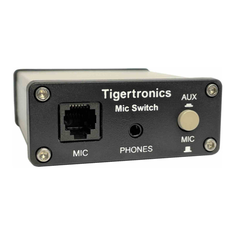
Front Panel
MIC –This jack is where you plug in your microphone. It
accepts a standard 8-pin RJ-45 modular plug.
PHONES –This jack is where you plug in your headphones
or an external speaker. It accepts a standard 3.5mm (1/8”)
stereo or mono audio plug (tip, ring and sleeve are all
switched).
AUX / MIC SWITCH –This push-button switch is used to
switch the radio between the microphone/headphones and the
aux communication device (SignaLink, TNC, etc.). When the
switch button is pressed in, the Aux communication device
(SignaLink, TNC, etc.) is connected to the radio. When the
switch button is out (not pressed in), the microphone and
headphones are connected to the radio.
Rear Panel
AUX –This jack is where you attach the aux communication
device (SignaLink, TNC, etc.). It accepts a standard 8-pin
4
MIC PHONES
RADIO AUX
Switch
Top View
Radio Other Comm
Device
MIC SPKR
OUT I/O AUDIO
IN
SPKR SPKR
(1) (2) (3) (4)
(5) (6)

RJ-45 modular plug.
AUX-SPKR –This 3.5mm audio jack connects to the aux
communication device (SignaLink, NC, etc.) where
applicable. It accepts a standard 3.5mm (1/8”) stereo or mono
audio plug (tip, ring and sleeve are all switched).
RADIO –This 8-pin RJ-45 jack attaches to the radio's mic
jack.
RADIO-SPKR - This 3.5mm audio jack connects to the
radio's External Speaker / Headphone audio output jack where
applicable. It accepts a standard 3.5mm (1/8”) stereo or mono
audio plug (tip, ring and sleeve are all switched).
- VISIT US ON THE INTERNET -
www.tigertronics.com
Our website contains the latest news about Tigertronics’
products, support information, and other information of
interest to Hams and SWLs. This is also the best source for
downloadable programs that work with our products. The
site is updated often, so stop in on a regular basis to get the
latest news and updates.
- YOUR COMMENTS WELCOME -
We have made every effort to make the SW-RJ45 Microphone
Switch the best product possible. We welcome any comments
or suggestions that you would like to make. Please drop us a
note to let us know about your experiences, tips you would like
to share with other users, or how we might do a better job for
you.
- LIMITED WARRANTY -
Tigertronics warrants the SW-RJ45 Microphone Switch to
be free of defects in material and workmanship for a period
of 90 days from the date of shipment. Tigertronics will
repair or replace, at its option, any parts found to be
defective during the warranty period. This warranty does
not include any unit that has been subject to misuse, neglect,
improper installation or operation. This warranty is in lieu
of all others, express or implied, and no person or
representative is authorized to assume for Tigertronics any
other liability in connection with the sale or use of this
product. Tigertronics will not be responsible for any
expense or loss of revenue or property incurred by the user
due to operation or malfunction of this equipment.
Tigertronics reserves the right to make any changes
including but not limited to the circuit, components or
firmware, or to incorporate new features, at any time,
without obligation.
- RETURN POLICY -
A Return Material Authorization Number (RMA#) must be
obtained before any product will be accepted for return or
repair. Items received without an RMA# clearly marked on
the OUTSIDE of the package WILL BE REFUSED. Items
being returned must be sent prepaid. Returned items should
include a note showing the RMA#, customer name, return
address, phone number, email address, and action requested.
Units returned for warranty repair must be accompanied by a
copy of the original invoice showing the date of purchase.
Customers wishing to return a product for REFUND, for
ANY REASON, must receive an RMA# within 15 days
from the shipping date shown on the original sales invoice.
Customers returning products for refund will be charged a
Restocking Fee equal to 20% of the purchase price, to cover
the cost of re-testing and re-stocking. Products that have
been damaged or modified in any way may not be returned.
Contact our Technical Support department for the RMA#.
- TECHNICAL SUPPORT -
BEFORE YOU CALL –The vast majority of technical
issues can be resolved with the information that is available
in this manual. Please take some time to read through it.
If you encounter a problem that you cannot resolve and you
have gone through the troubleshooting information available
in this manual and on our website, then please contact our
Technical Support Staff at (541) 862-2639. They are
available every Monday, Wednesday, and Friday, from
1PM to 5PM Pacific Time (4PM to 8PM Eastern). Be
sure to have your equipment available for testing when you
call. Unless you are located over-seas or have extenuating
circumstances, please DO NOT mail, email, or fax your
technical inquiries. We realize that calling is a little more
expensive, but more can be accomplished in a few minutes
on the phone than can be done in hours of writing!
- TROUBLESHOOTING -
This section covers the most common issues that you may
experience with this product. If your problem is not covered
here then please see the Support pages of our website at
www.tigertronics.com. If you are still unable to resolve the
issue, then please see the “Technical Support”section of
this manual for instructions on contacting our Technical
Support Staff by telephone.
My microphone or SignaLink (or other communication
device) does not work when connected through the switch.
If you have grounded the switch chassis then you may have
grounded the wrong line by mistake. Please see
“Grounding The Switch Chassis”on page 1 of this manual
and use the steps there to double-check your work. You can
also try removing the ground jumper to see if that resolves
the issue. If it does, then you have most likely installed the
ground jumper incorrectly.
If you have enabled RFI filtering by means of the JP1-JP8
jumpers, then you can try removing them to see if it affects
the problem (see “Enabling RFI Filtering”on page 2 of
5

this manual). The built-in RFI filtering should not normally
cause any issues regardless of the microphone or device
you're using. If you believe that this is the cause of the issue
then please contact us with the details.
If the above steps do not resolve the issue, then try plugging
the microphone (SignaLink, TNC, etc.) into the radio
directly to confirm that it works with a direct connection. If
the problem persists when the microphone or device is
directly connected to the radio, then the issue is most likely
due to a problem with the microphone or device (not the
switch).
SignaLinkäis a trademark of Tigertronics
Copyright © 2001-2022 Tigertronics - All Rights Reserved
(8/22/2022 Rev-A)
6
Table of contents
Other Tigertronics Switch manuals
