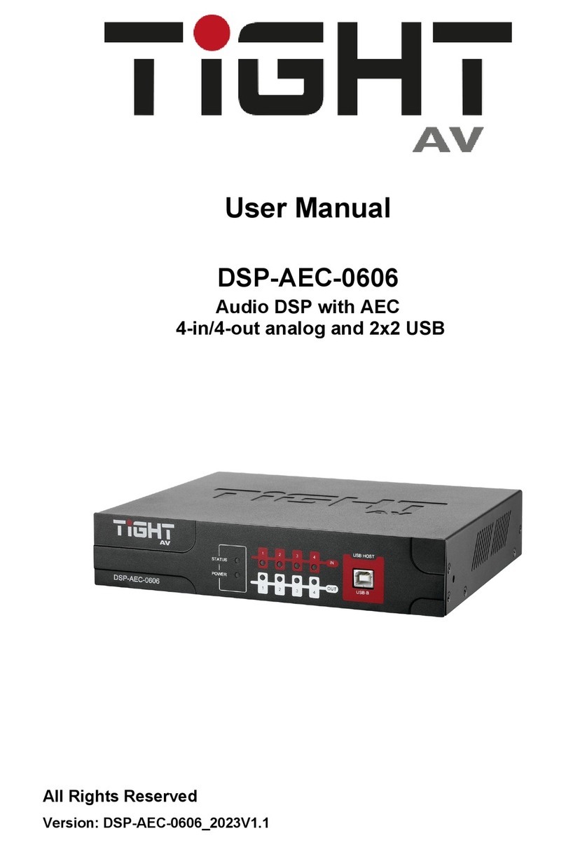
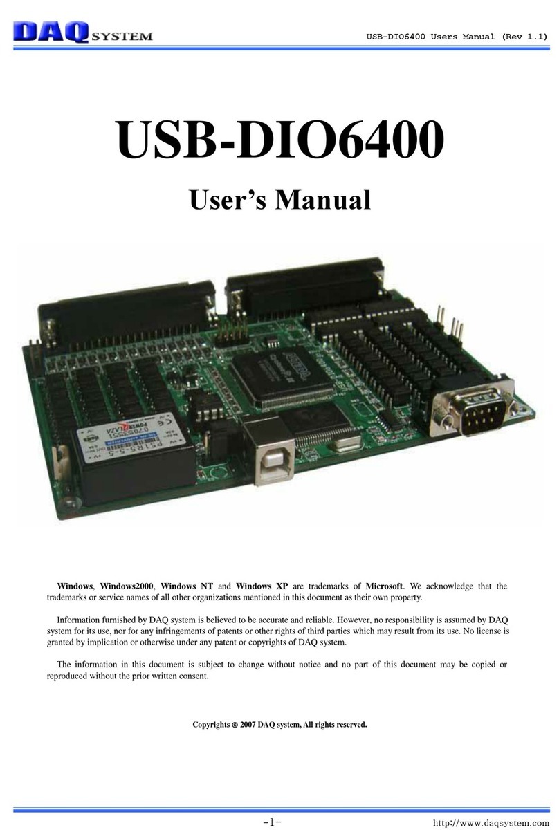
TiGHT AV DSP-AEC-1410 User manual

User Manual
DSP-AEC-1410
Audio DSP with AEC
12-in/8-out analog and 2x2 USB
All Rights Reserved
Version: DSP-AEC-1410_2023V1.1

Audio DSP with AEC 12-in/8-out analog and 2x2 USB
1
Preface
Read this user manual carefully before using the product. Pictures shown in this
manual are for reference only. Different models and specifications are subject to real
product.
This manual is only for operation instruction, please contact the local distributor for
maintenance assistance. The functions described in this version were updated by
July 2023. In the constant effort to improve the product, we reserve the right to make
functions or parameters changes without notice or obligation. Please refer to the
dealers for the latest details.
FCC Statement
This equipment generates, uses and can radiate radio frequency energy and, if not
installed and used in accordance with the instructions, may cause harmful
interference to radio communications. It has been tested and found to comply with
the limits for a Class A digital device, pursuant to part 15 of the FCC Rules. These
limits are designed to provide reasonable protection against harmful interference in a
commercial installation.
Operation of this equipment in a residential area is likely to cause interference, in
which case the user at their own expense will be required to take whatever measures
may be necessary to correct the interference.
Any changes or modifications not expressly approved by the manufacture would void
the user’s authority to operate the equipment.

Audio DSP with AEC 12-in/8-out analog and 2x2 USB
2
SAFETY PRECAUTIONS
Please read this manual before installing or using the product. Review the following
safety precautions.
The lightning symbol in the triangle is used to alert you to the presence of dangerous
voltage inside the product that may cause a risk of electric shock to anyone opening the
case. It is also used to indicate improper installation or handling of the product which could
damage the electrical system of the product or other equipment connected to the product.
The exclamation point in the triangle is used to alert you to important operating and
maintenance instructions. Failure to follow these instructions may result in injury or
product damage.
Be careful with electricity:
Power Outlet: To avoid electric shock, make sure that the electrical plug used on
the product power cord matches the electrical outlet used to supply power to the
TiGHT AV product. Use the power adapter and power connection cables designed
for this unit.
Power Cord: Make sure the power cord is routed so that it will not be walked on or
pinched by heavy objects.
Lightning: To protect against lightning or when the product is left unattended for a
long period of time, unplug it from the power source.
Also follow these precautions:
Ventilation: Do not block the ventilation slots, if any, on the product or place heavy
objects on it. Blocking the airflow could cause damage. Arrange the components so
that air can circulate freely. Ensure adequate ventilation if the product is placed on a
stand or cabinet. Place the product in a well-ventilated place, away from direct
sunlight or any heat source.
Overheating: Avoid stacking the DSP-AEC-1410 on top of a hot component, such
as a power amplifier.
Risk of Fire: Do not place the unit on top of easily combustible materials, such as
rugs or fabrics.
Proper Connections: Make sure all cables and equipment are connected to the unit as
described in this manual.
Object Entry: To avoid electric shock, never stick anything in the slots on the case, or
remove the cover when connected to a power supply.
Water Exposure: To reduce the risk of electric shock or fire, never expose the unit to
rain or moisture.
Cleaning: Do not use aerosol cleaners or liquid to clean this unit. Always unplug
the power source to the device before cleaning the unit.
ESD: Handle this unit with proper ESC care. Failure to do so can result in failure.

Audio DSP with AEC 12-in/8-out analog and 2x2 USB
3
Table of Contents
Quick Start Guide ....................................................................................................... 5
1. Product Introduction................................................................................................ 6
1.1 Key Features..................................................................................................... 6
1.2 Package List...................................................................................................... 6
1.3 Customer Service.............................................................................................. 7
1.4 Technical Specifications.................................................................................... 7
1.5 Front Panel Features......................................................................................... 9
1.6 Rear Panel Features ......................................................................................... 9
1.6 Signal Flow Chart ............................................................................................ 11
2. DSP Software ....................................................................................................... 12
2.1 Software Requirements................................................................................... 12
2.2 Software Installation ........................................................................................ 12
2.3 Software Operation ......................................................................................... 12
2.3.1 File Menu .................................................................................................. 13
2.3.2 Settings Menu ........................................................................................... 14
2.3.2.1 Device Settings .................................................................................. 14
2.3.2.2 GPIO Settings.................................................................................... 15
2.3.2.3 Group Settings................................................................................... 18
2.3.2.4 Preset Name ...................................................................................... 19
2.3.2.5 Panel Setting...................................................................................... 20
2.3.2.6 User Interface .................................................................................... 21
2.3.2.8 UserAdmin ......................................................................................... 23
2.3.2.9 EditPassword ..................................................................................... 24
2.3.3 Help Menu................................................................................................. 24
2.3.3.1 About ................................................................................................. 24
2.3.3.2 Support .............................................................................................. 24
2.3.3.3 Command copy.................................................................................. 24
2.3.4 Theme Menu............................................................................................. 25
2.3.4.1 Light Mode ......................................................................................... 25
2.3.4.2 Dark Mode ......................................................................................... 25
2.3.5 Device List................................................................................................. 26
2.3.6 Top Right Settings..................................................................................... 27
2.3.7 Home Tab ................................................................................................. 27

Audio DSP with AEC 12-in/8-out analog and 2x2 USB
4
2.3.7.1 Processing modules slots .................................................................. 28
2.3.8 Module Tabs ............................................................................................. 29
2.3.8.1 Inputs / Outputs.................................................................................. 29
2.3.8.2 AutoMixer........................................................................................... 30
2.3.8.3 AEC (Acoustic Echo Cancellation)..................................................... 33
2.3.8.4 ANS (Automatic Noise Suppression) ................................................. 34
2.3.8.5 Matrix ................................................................................................. 34
2.3.8.6 Meters................................................................................................ 35
2.3.8.7 Camera .............................................................................................. 35
2.3.9 Channel Processing Modules.................................................................... 38
2.3.9.1 Input Source....................................................................................... 38
2.3.9.2 Expander (Inputs) .............................................................................. 39
2.3.9.3 Compressor (Inputs) .......................................................................... 40
2.3.9.4 AGC (Automatic Gain Control) (Inputs).............................................. 41
2.3.9.5 PEQ (Parametric Equalizer)............................................................... 42
2.3.9.6 AFS (Adaptive Feedback Suppression) (Inputs)................................ 43
2.3.9.7 GEQ (Graphical Equalizer) ................................................................ 44
2.3.9.8 Gate (Inputs)...................................................................................... 45
2.3.9.9 Ducker (Inputs) .................................................................................. 46
2.3.9.10 ANC (Ambient Noise Compensation) (Inputs).................................. 47
2.3.9.10 Filter (Outputs) ................................................................................. 48
2.3.9.11 Delay (Outputs)................................................................................ 49
2.3.9.12 Limiter (Outputs) .............................................................................. 49
2.3.9.13 Output Setting ................................................................................. 50
2.3.10 USB Soundcard ...................................................................................... 51
3. Dante control and routing ..................................................................................... 51
3.1 Dante Controller Basic Operation.................................................................... 51
3.3.1 Overview of Dante Controller: ................................................................... 52
4. Control.................................................................................................................. 55
4.1 External Control Programmer.......................................................................... 55
4.2 Control Protocol............................................................................................... 55
4.2.1 V1 Protocol................................................................................................ 55
4.2.2 V2 Protocol................................................................................................ 56
4.2.3 Preset Structure (V1 and V2 protocol) ...................................................... 57

Audio DSP with AEC 12-in/8-out analog and 2x2 USB
5
4.2.4 UDP to RS232/RS485 (V2 protocol only).................................................. 57
4.2.4 RS232/RS485 to UDP (V2 protocol only).................................................. 58
4.2.5 Central Control Response control ON/OFF (V2 protocol only):................. 59
4.2.6 Feedback and response to SET or GET commands (V1 and V2)............. 59
4.3 Appendix A: Module ID.................................................................................... 60
4.4 Appendix B: Module Parameters..................................................................... 61
4.5 Appendix C, Command Structure Examples ................................................... 71
4.5.1 V1 examples ............................................................................................. 71
4.5.2 V2 examples ............................................................................................. 75
5. Environment and recycle information.................................................................... 76
5.1 Disposal of electric and electronic devices EC Directive 2012/19/EU ............. 76
5.2 Packaging recycling information...................................................................... 77
Quick Start Guide
1. Install the TiGHT DSP software found on the product page at www.TiGHTAV.com
2. Connect the computer running the software directly to the DSP via network cable, or
connect to the same network.
3. Open software and click ”Device List” in the top right corner and connect to the DSP.
4. Make sure your computer and TiGHT DSP are connected on the same network and
using correct IP settings.
5. Click on ”Connect”.
You”re all set, enjoy your TiGHTAV product!

Audio DSP with AEC 12-in/8-out analog and 2x2 USB
6
1. Product Introduction
Thanks for choosing the TiGHT AV DSP-AEC-1410. The DSP-AEC-1410 is an audio
signal processing unit with analog and a USB interface for computer audio. The unit
is configured and controlled from a Windows application that presents an easy-to-use
GUI. Powerful processing with EQ, dynamics, mixing and matrix combined with
advanced acoustic echo cancellation (AEC) makes this unit suitable for a wide range
of use cases.
A single network cable connected to a PoE network switch allows for both power and
control. Analog audio inputs support both microphone and line level sources.
Phantom power is selectable individually per analog input channel.
USB connection to host computer works as a sound card for easy computer audio
connectivity for both playback and recording.
1.1 Key Features
•12x8 analog inputs and outputs
•2x2 USB channels with processing for computer audio playback and recording
•Powerful DSP processing with matrix and mixer
•AEC (Acoustic Echo Cancellation)
•Ducker
•Camera tracking feature
•Easy to use GUI with configurable processing modules layout
•16 user configurable presets for easy recall
•Device snapshot export and mass import
•Light or dark theme selections
•Admin and user account support
•Redundancy mode for critical applications
•Open API for external control via ethernet (UDP) or RS-232/485
•External control from custom software or 3rd party control systems
1.2 Package List
•1 x DSP-AEC-1410
•7 x 12-pin and 1 x 6-pin Terminal Block connectors
•1 x 1,5m USB 2.0 cable (Type A to Type B)
•1 x EU AC power cable
•1 x UK AC power cable
•1 x Screwdriver
•4 x Rubber Feet
Note: Please contact your distributor immediately if any damage or defect in the
components is found.

Audio DSP with AEC 12-in/8-out analog and 2x2 USB
7
1.3 Customer Service
TiGHT AV provide a limited warranty for the product within five years counting from
date of purchase (The purchase invoice shall prevail).
For more information see TiGHT AV general Warranty Statement at
https://tightav.com/warranty-statement or just scan the QR-code.
1.4 Technical Specifications
DSP Pr
ocessor
Type
ADI SHARC 21489
DSP Handling Capacity
400 MIPS, 1,6 GFLOPS
Input
Inputs
(12)
Analog Mic/line Audio
Input Connector
(
3) 12-pin Green Terminal Blocks
Phantom Power
48V (Max 10mA), selectable
per input
Output
Outputs
(8)
Analog Line Audio
Output Connector
(
2) 12-pin Yellow Terminal Blocks
Interface
Ethernet
(
1) LAN, 10/100/1000 Base-T Ethernet
Ethernet Connector
(2) RJ45
USB
(1) USB 2.0, Type B
Serial
(1) RS
-232, (1) RS-485
Serial Connector
(
1) 6-pin Brown Terminal Blocks
GPIO
(
8) GPIO
GPIO Connector
(2
) 12-pin Blue Terminal Blocks

Audio DSP with AEC 12-in/8-out analog and 2x2 USB
8
Audio Performance
Input Gain
0
- 48dB in 3dB steps
Frequency Response
±0.
2dB (20Hz~20KHz)
Maximum Level
+18dBu
THD + Noise
0.003%@4dBu
Input Dynamic Range
110dB
Output Dynamic Range
112dB
Background Noise (A
-weighted)
-
91dB
Common Mode Rejection Ratio @60Hz
80dB
Channel Isolation @1KHz
108 dB
Input Impedance (Balanced)
9
.4kΩ
Output Impedance (Balanced)
102Ω
System Latency
<3ms
Sample Rate
48 kHz
Bit
Depth
24
Bit
General
Power requirements
AC110~240V 5
0Hz-60Hz
Maximum Power Consumption
<4
0W
Rack Space
19
" Rack (1HE)
Dimensions (W x D x H)
482
mm x 264mm x 44mm
Shipping Weight
3
kg
Operating Temperature
0 ~ +40
℃
Storage Temperature
-
25 ~ +70℃
Relative Humility
10%
- 90%
Compliance
Compliance
FCC, CE
Environmental Compliance
RoHS, REACH, WEEE

Audio DSP with AEC 12-in/8-out analog and 2x2 USB
9
1.5 Front Panel Features
1. Power LED: A green LED indicates the unit is receiving power.
2. System LED: A blinking green LED indicates that program is running.
3. I/O LEDs: A green LED indicates the unit receiving or outputting an analog
signal.
4. LED Display: Provides a quick status and information overview. Input and
output channel levels, Model Name, IP-address, MAC address and Firmware
version are displayed in a loop sequence.
5. USB Audio: USB soundcard connection for Audio over Type-B USB cable.
1.6 Rear Panel Features
1. Ground:Secure to earth ground according to code.
2. Power Input:AC 110V-240V 50/60Hz power supply input with On/Off switch.
Supports a maximum 40W power.
3. Ethernet Port:RJ45 connector, 10/100/1000 Base-T Ethernet. This interface is
used for communication with computer software, ACP-ENC-OLED control panel
or any third-party external control system.
4. RESET: Resets the DSP to factory settings.
5. CONTROL: RS-232 and RS-485 serial communication ports that connect to
third-party control systems or devices. Default port settings: 115200 baud, 8
data bits, 1 stop bit, no parity, no flow control.
6. GPIO: 8- channel General Purpose I/O. The function of the GPIO pins can be
configured in the GPIO Settings section of the TiGHT AV DSP software.
GPIO Input: The port value is considered “low” when voltage level is less than
0.3VDC and considered “high” when voltage level is greater than 2VDC. Inputs
can support up to 12VDC

Audio DSP with AEC 12-in/8-out analog and 2x2 USB
10
GPIO Output: When the port is triggered ´”high” it will output 5VDC @ 100mA.
When triggered “low” it will equal ground.
Note: Maximum combined current if all 8GPIO is configured as outputs is
500mA.
7. Analog Inputs: Balanced or Unbalanced high impedance inputs. Line or Mic
Level supported with +48VDC phantom power.
Signal Label
XLR
TRS
+
Pin 2
Tip
-
*
Pin 3
Ring
Pin 1
Sleeve
*used with “jumper” when using unbalanced
8. Analog Outputs: Balanced or Unbalanced outputs. 24bit DA Conversion.
Signal
Label
XLR
TRS
+
Pin 2
Tip
-
*
Pin 3
Ring
Pin 1
Sleeve
*do not use (-) for unbalanced
9. Serial Communication:RS-232/485 connections for remote control devices,
such as a control panel.
Signal
Label
Signal
Rx
RS-232
Receive
Ground
Tx
RS-232
Transmit
Signal
Label
Signal
+12V
AUX
Power
A
A (-)
B
B (+)
Ground

Audio DSP with AEC 12-in/8-out analog and 2x2 USB
11
1.6 Signal Flow Chart

Audio DSP with AEC 12-in/8-out analog and 2x2 USB
12
2. DSP Software
2.1 Software Requirements
TiGHT AV DSP software:
A Windows computer with a processor of 1 GHz or higher and:
Windows 7 or higher version.
1 GB free storage space.
1024 x 768 resolution.
24 bit or higher color.
2GB or higher memory.
Network (Ethernet) port.
Audinate software’s:
Refer to Audinate minimum requirements recommendations.
2.2 Software Installation
1. Download software from the DSP-AEC-1410 product page at
https://www.TiGHTAV.com/. Or open a web browser and type in the IP address of
the DSP´s control interface and download the software stored on the device.
2. Double click the downloaded file and install by following the instructions on the
screen.
3. After installation is complete, launch the software by clicking the TiGHT AV
DSP software icon.
4. Wait for the software to launch, may take 1-15s to start.
2.3 Software Operation
After the software has opened, click ”OK” on your selected model (this startup
selection box can be turned off under “Device Settings”.

Audio DSP with AEC 12-in/8-out analog and 2x2 USB
13
To connect to the DSP click on ”Device List” and
choose your DSP from the list. Then click
”Connect”. The software will automatically scan the
network for available DSPs. The software will be
able to find DSPs even if they are not configured
with an IP address according to the computer
network configurations if the DSP can be reached.
First time setup of a DSP, the DSP will have the
default static IP-Address 169.254.10.227 with
subnet mask 255.255.0.0. Click “Set IP” button to
configure a new static IP address. If DHCP is
needed connect to the DSP then go to “Settings”
tab and select “Device settings” (see section Device
settings)
The following shows the Home Tab view of the interface (using Light Mode theme).
Use button and select model to add multiple DSPs to control simultaneously.
2.3.1 File Menu
Open: The File Menu gives you the option of importing saved presets from your
computer or saving presets to your computer.
Note: This option is only available offline. To import presets from your computer to an
online DSP use the “Import Preset” feature described in section 2.3.6.
Save As:Export current preset and save on your computer.

Audio DSP with AEC 12-in/8-out analog and 2x2 USB
14
Export All: Exports a full device snapshot with all configurations and presets. IP
settings will not be exported. Save snapshot file on your computer.
Import All: Imports a snapshot file stored on a computer.
Note: Unit will disconnect after import is done and users need to connect again.
2.3.2 Settings Menu
For the Device Settings Menu to be accessible the software and DSP-AEC-1410
must be connected.
2.3.2.1 Device Settings
Device Name: Set the name of the device and the name will display anywhere the
device is addressed. The name is saved into the hardware.
Device IP Address: Set the IP address of the LAN interface.
Note: It doesn´t change the Dante interface IP Address, this is done in Audinate’s
Dante Controller Software.
Gateway: Set the default gateway for the network.
Netmask: Set the network mask associated with the desired subnet.
Mac Address: Shows the MAC address of the control interface.
Note: The MAC address for Dante interface is different and can be found by using
Dante Controller.
Default Preset: Sets the default preset the device loads upon a power cycle event.
Can be set to one of the 16 presets or set to last active preset prior to the power
cycle.

Audio DSP with AEC 12-in/8-out analog and 2x2 USB
15
Set Up Redundancy: In case of serious system
failure the DSP functionality can switch over to a
redundancy (backup) DSP within 3 seconds. When
enabled Unit will now also show “Master” status in the
top left.
BackupDeviceIP: IP address for the redundancy (backup) DSP.
Central Control Response: Enable this when using an external controller that
expects a response to control messages (see Appendix C, Command Structure
Examples).
Real Time Save: When enabled, active preset changes are saved in real time.
Enable this will ensure the exact state of the device to be restored upon a power
cycle if ”Previous Loaded Preset” is selected in the ”Default Preset” parameter. If
Real Time Save is set to ”Off”, changes that are not manually saved will be lost after
a power cycle.
Enable Model Selection Box: When enabled, upon starting the software the model
selection window will appear.
UDP Control Port: Shows the UDP control port for remote communication with the
DSP-AEC-1410.
RS-232/RS-485: Set the baud rate, Data bit, Stop bit and Parity bit for the serial port
of the device.
OK: All settings done in the Device Setting window are saved to the device and the
window will close.
Cancel: Will close the window and no changes are saved.
2.3.2.2 GPIO Settings
The DSP-AEC-1410 has 8 GPIOs that allows for independent input or output
configuration.
Input GPIOs control options: Preset, Route, Gain, Mute/Unmute, Command, and
Analogue To Digital Gain.
Output GPIOs control options: Preset, Level and Mute/Unmute.

Audio DSP with AEC 12-in/8-out analog and 2x2 USB
16
Channel: 8 channel buttons select the channel to be configured.
Direction: Sets either input, GPI, or output, GPO for selected channel. Output and
Input selections has different control options.
Control type (Inputs only): Selects the control option type for input, GPI.
Preset: Changes the preset value when triggered.
Trigger type: “High Level Trigger” will trigger the
channel when the voltage is above the threshold.
“Low Level Trigger” will trigger the channel with the
voltage is below the threshold.
Preset: Selects the preset to be applied upon trigger.
Route: Creates a route in Matrix when triggered.
Trigger type: “High Level Trigger” will trigger the
channel when the voltage is above the threshold.
“Low Level Trigger” will trigger the channel with the
voltage is below the threshold.
Inputs: Input channel in Matrix.
Outputs: Output channel in Matrix.
Gain: Changes the gain value for selected
input/output channel or system.
Trigger type: “High Level Trigger” will trigger the
channel when the voltage above the threshold. “Low
Level Trigger” will trigger the channel with the voltage
is below the threshold.
Channel: Selects which input, output or “System”
channel will be affected by the gain change.
Step: Sets the amount of gain (dB) increase or decrease for the trigger.

Audio DSP with AEC 12-in/8-out analog and 2x2 USB
17
Mute/Unmute: Will mute selected channel when the
trigger is active and unmute the channel when it is
inactive.
Trigger type: “High Level Trigger” will mute the
channel when the voltage is above the threshold.
“Low Level Trigger” will mute the channel with the
voltage is below the threshold. “Triggered by low
level (Cancelled by high level)” will trigger the
channel when the voltage is below the threshold and automatically unmute when the
voltage is above the threshold. “Triggered by high level (Cancelled by low level)” will
trigger the channel when the voltage is above the threshold and automatically
unmute when the voltage is below the threshold.
Channel: Selects which input, output or “System” channel will be muted/unmuted.
Command: Outputs a command via RS-232 when
triggered.
Trigger type: “High Level Trigger” will trigger the
channel when the voltage above the threshold. “Low
Level Trigger” will trigger the channel with the
voltage is below the threshold.
Command: String of HEX to be output via RS-232.
Analog To Digital Gain: If a potentiometer is
connected to the GPIO, the selected channel gain
will be adjusted accordingly.
Channel: Selects which input, output or “System”
channel will be adjusted.
Output Type (outputs only): Selects the control option type for output, GPO.
Preset: Trigger event is initiated by a Preset
selection.
Output type: “Output low level” will set the channel
pin to ground. “Output high level” will set the
channel pin to +5VDC.
Preset: Selects the preset that will initiate the
trigger event.

Audio DSP with AEC 12-in/8-out analog and 2x2 USB
18
Level: Trigger event is initiated when channel level
exceeds a set level threshold.
Output type: “Output low level” will set the channel
pin to ground. “Output high level” will set the channel
pin to +5VDC.
Channel: Selects which input or output channel will
be affected by the gain change.
Level:Sets the gain threshold which will initiate the trigger event.
Mute: Trigger event it initiated when a selected
channel enters mute state.
Output type: “Output low level” will set the channel
pin to ground. “Output high level” will set the channel
pin to +5VDC.
Channel: Selects which input or output channel
mute state will initiate the trigger event.
Save As…: Save the current GPIO configuration to a file. This can be done offline for
commissioning at a later stage or saving record of configurations for a finished
project.
Open…: Import a previously saved GPIO configuration file.
Save: Save the current configuration file to the DSP.
2.3.2.3 Group Settings
The group setting window has separate tabs for input and output groups. 7 groups for
input channels and 5 groups for output channels can be set in each tab. A channel
can only participate in one group. In the same group, the channel volume/gain control
and mute functions are linked. Individual level differences are kept. Other functions
are not linked. For pairwise linking of all channel parameters, use the link button
below the channel fader.

Audio DSP with AEC 12-in/8-out analog and 2x2 USB
19
The relationship between groups and link: The channel participating in a group
will not participate in LINK, which means the group’s priority is higher than LINK. The
difference between groups and LINK is that groups can only control channel gain
and mute, while LINK includes all parameters in the channel. LINK sets volume/gain
to same value whereas the Group keeps the differences set by the faders.
2.3.2.4 Preset Name
In this window, all 16 preset names can be changed
in one window.
All changes made here will correspond to other
features in the software where Preset Names are
available.
Table of contents
Other TiGHT AV Computer Hardware manuals
Popular Computer Hardware manuals by other brands
Acronova Technology
Acronova Technology Nimbie Chorus NBCH07 Series user manual
Acces
Acces PCI-DIO-24D user manual

Kontron
Kontron nanoETXexpress-SP user guide
NEC
NEC IE-703116-MC-EM1 user manual
AXIOMTEK
AXIOMTEK AIE900-XNX Series user manual

Jameco Electronics
Jameco Electronics Superpro Series user manual
