H3C NIC-FC730i-Mb-2-32G User manual

i
Contents
1 Safety information ································································································································1-1
1.1 General operating safety···················································································································1-1
1.2 Electrical safety·································································································································1-1
1.3 ESD prevention·································································································································1-1
2 About the NIC·······································································································································2-1
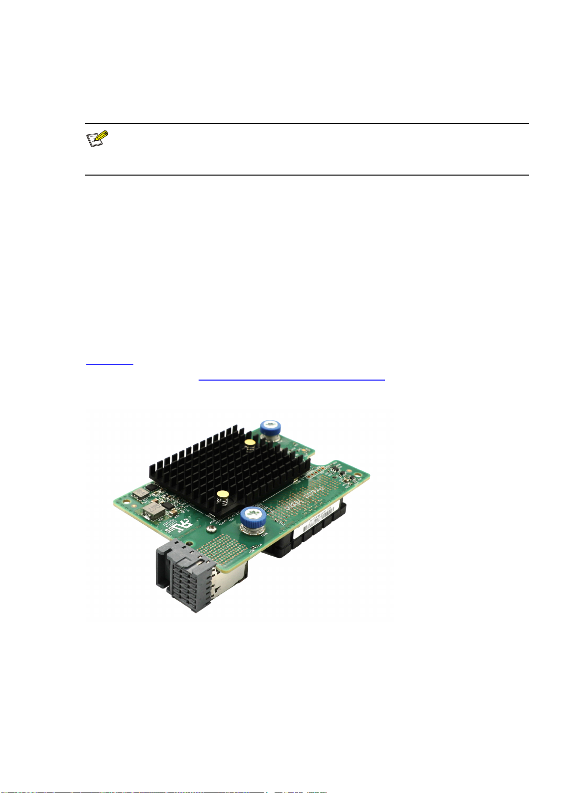
2.1 Overview ···········································································································································2-1
2.2 Appearance·······································································································································2-1
2.3 Specifications····································································································································2-1
2.3.1 Product Specifications············································································································2-2
2.3.2 Specifications ·························································································································2-2
3 Feature Introduction·····························································································································3-1
3.1 Supported Features ··························································································································3-1
3.2 Function Introduction·························································································································3-1
4 Software and Hardware Compatibility Relationship·············································································4-1
4.1 Supported Operating Systems··········································································································4-1
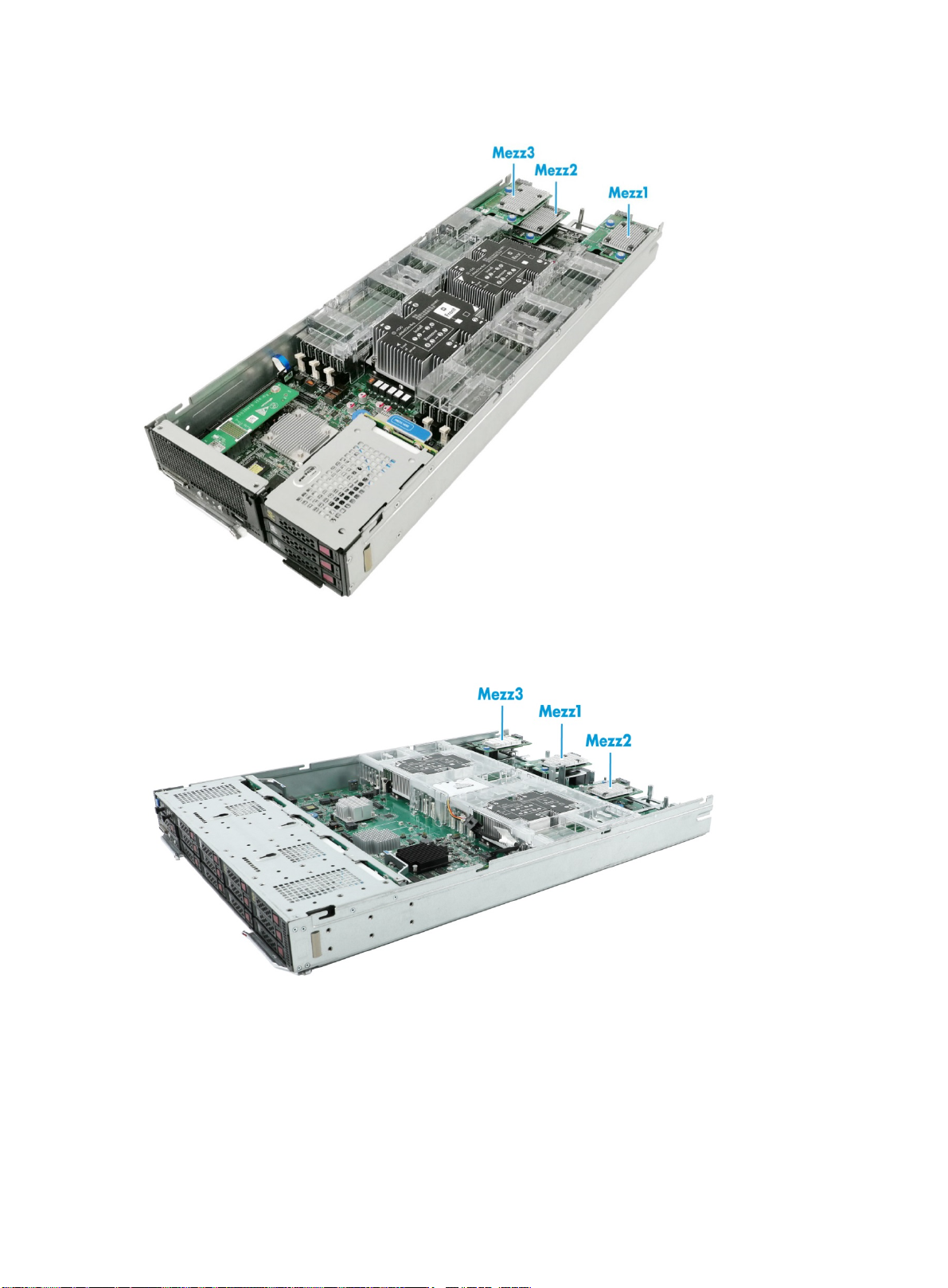
4.2 Blade Servers Supported by the NIC································································································4-1
4.3 ICMs Supported by NIC····················································································································4-3
4.3.1 Compatibility between the NIC and ICM ················································································4-3
4.3.2 Connection Between the NIC and ICM ··················································································4-4
4.4 Network Application Logic Diagram··································································································4-6
5 Configuring the NIC······························································································································5-1
5.1 Port Correspondence between the NIC and ICM·············································································5-1
5.2 Identifying NIC Ports under OS·········································································································5-1
5.2.1 Linux Operating Systems·······································································································5-1
5.2.2 Windows Operating Systems·································································································5-2
5.3 Installing and Uninstalling the NIC Driver under OS·········································································5-2
5.3.1 Linux Operating Systems·······································································································5-3
5.3.2 Windows Operating Systems·································································································5-4
5.4 Configuring FC SAN··························································································································5-7
5.4.1 Linux Operating Systems·······································································································5-7
5.4.2 Windows Operating Systems·································································································5-8
5.4.3 Installing a Linux OS ············································································································5-14

ii
5.5 Configuring NPIV ····························································································································5-18
5.5.1 Installing the elxocm Tool·····································································································5-18
5.5.2 NPIV Configuration Steps ····································································································5-20
6 Acronyms and Abbreviations ···············································································································6-1

1-1
1 Safety information
To avoid bodily injury or device damage, read the following information carefully before you
operate the network adapter.
1.1 General operating safety
To avoid bodily injury or damage to the device, follow these guidelines when you operate the
network adapter:
•
Only H3C authorized orprofessional engineers are allowed to install or replacethe network
adapter.
•
Before installing or replacing the network adapter, stop all services, power off the blade
server, and then remove the blade server.
•
When disassembling, transporting, or placing the blade server, do not useexcessive force.
Make sure you use even force and move the device slowly.
•
Place the blade server on a clean, stable workbench or floor for servicing.
•
To avoid being burnt, allow the blade server and its internal modules to cool before
touching them.
1.2 Electrical safety
Clear the work area of possible electricity hazards, such as ungrounded chassis, missing safety
grounds, and wet work area.
1.3 ESD prevention
Electrostatic charges that build up on people and other conductors might damage or shorten the
lifespan of the network adapter.
1. Preventing electrostatic discharge
To prevent electrostatic damage, follow these guidelines:
•
Transport or store the network adapter in an antistatic bag.
•
Keep the network adapters in antistatic bags until they arrive at an ESD-protected area.
•
Place the network adapter on an antistatic workbench before removing it from its antistatic
bag.
•
Install the network adapter immediately after you remove it from its antistatic bag.
•
Avoid touching pins, leads, or circuitry.

1-2
•
Put away the removed network adapter in an antistatic bag immediately and keep it secure
for future use.
2. Grounding methods to prevent electrostatic discharge
The following are grounding methods that you can use to prevent electrostatic discharge:
•
Wear an ESD wrist strap and make sure it makes good skin contact and is reliably
grounded.
•
Take adequate personal grounding measures, including wearing antistatic clothing and
static dissipative shoes.
•
Use conductive field service tools.
Use a portable field service kit with a folding static-dissipating work mat

2-1
2 About the NIC
Note
Figures in this manual are for illustration purposes only. The actual product may vary.
2.1 Overview
NIC-FC730i-Mb-2*32G (hereinafter referred to as FC730i) is an FC NIC with two 32G FC ports. It
provides network interfaces for blade servers to connect to ICM slots, and is applicable to B16000
blade enclosure. FC730i exchanges data with blade servers via x8 bandwidth PCIe lanes and
connects to the ICM through two 32G FC ports via the mid-backplane. It supports applications
such as FC SAN, FC Boot and NPIV.
2.2 Appearance
Figure 2-1 shows the appearance of FC730i. It applies to B16000 blade servers. For the specific
installation position, see 4.2 Blade Servers Supported by the NIC.
Figure 2-1 Appearance of FC730i
2.3 Specifications
This section introduces the product specifications and technical parameters of the NIC.

2-2
2.3.1 Product Specifications
Table 2-1 Product Specifications
Properties Description
Basic properties
NIC type FC NIC
Chip model LPe32002
Max. power
consumption 20 W
Input voltage 12 V DC
Data channel bus PCIe3.0 x8
Network properties
Number and type of
user ports 2*32G
User port transfer rate 32 Gb/s
Full duplex/Half duplex Full duplex
Compatible standards
FC-PI-4, FC-PI-5, FC-PI-6, FC-FS-3, FC-LS-2, FC-GS-6, FC-DA, FC-DA-2, FC-SP-2,
FCP-4, SPC-4, SBC-3, SSC-4, FC-PH, FC-PH-2, FC-PH-3, FC-PI, FC-PI-2, FC-PI-3,
FC-FS, FC-GS-2/3/4/5, FCP-2/3, FC-HBA, FC-TAPE, FC-MI, SPC-3, SBC-2, SSC-2,
SSC-3
2.3.2 Specifications
Table 2-2 Specifications
Category Item Description
Physical
specifications Dimensions
(H × W × D) 25.05 mm x 61.60 mm x 95.00 mm
Environmental
specifications
Temperature Operating temperature: 5°C to 45°C
Storage temperature: -40°C to 70°C
Humidity •Operating humidity: 8% to 90%RH (non-condensing)
•Storage humidity: 5% to 95%RH (non-condensing)
Altitude
•Operating altitude: -60 m to +5000 m (The allowed maximum
temperature decreases by 0.33°C as the altitude increases by 100 m
from 900 m.)
•Storage altitude: -60 m to +5000 m

3-1
3 Feature Introduction
3.1 Supported Features
This section introduces the features supported by the FC730i NIC.
Table 3-1 NIC features
Feature Supported
FC SAN √
FC Boot √
N_Port_ID Virtualization (NPIV) √
3.2 Function Introduction
1. FC SAN
The FC730i NIC supports FC SANs.
FC SAN is a remote high-speed storage technology. An FC SAN usually consists of a RAID
connected to a fiber channel. It uses a scalable network topology to provide multiple selectable
data switches between any nodes within the SAN by adopting direct connection of an optical
channel with high transmission rate. It centralizes data storage management within a relatively
independent storage area network. It is actually a technology that integrates storage devices,
connection devices and interfaces in a high-speed network. It undertakes data storage tasks and
isolates them from LAN services. Storage data streams do not occupy the service network
bandwidth.
2. FC Boot
The FC730i NIC supports FC Boot.
FC Boot technology is an extension based on FC SAN technology. It is used to boot operating
systems from remote storage devices through FC NICs and SANs. The premise is that the
operating system has been installed into the storagedevice through the FC SAN. FC Boot enables
local diskless boot of the operating system, achieve secure, high-speed and reliable unified
management by using storage devices.
3. NPIV
The FC730i NIC supports NPIV.
When working in FCoE mode, its ports support NPIV. Each port supports a maximum of 31
N_Port_IDs for NPIV. In addition to the physical port's own N_Port_ID, each port supports a
maximum of 32 N_Port_IDs.

3-2
The main function of NPIV is to virtualize multiple interface N_Port IDs on one physical port N of
the FC NIC, and to associate any F_Port on the FC switch to these multiple N_Port IDs. In this way,
systems in different partitions on the virtualization platform can share one FC NIC physical port.

4-1
4 Software and Hardware Compatibility Relationship
4.1 Supported Operating Systems
For the compatibility relationship between the NIC and OS, see OS compatibility query tool.
4.2 Blade Servers Supported by the NIC
Table 4-1 describes the blade server models supported by the NIC and their installation positions.
Table 4-1 Blade servers supported by FC730i
Model of Blade
Server Model of
Blade Server
Number of
Mezz NIC
Slots Installation Position Diagram
H3C UniServer
B5700 G3
2-way
half-width
blade server 3 Mezz 1, Mezz 2 and Mezz 3 NIC installation position on
a 2-way half-width blade
server
H3C UniServer
B5800 G3
2-way
full-width
blade server 3 Mezz 1, Mezz 2 and Mezz 3 NIC installation position on
a 2-way full-width blade
server
H3C UniServer
B7800 G3
4-way
full-width
blade server 6 Mezz 1, Mezz 2, Mezz 3, Mezz
4, Mezz 5 and Mezz 6
NIC installation position on
a 4-way full-width blade
server
H3C UniServer
B5700 G5
2-way
half-width
blade server 3 Mezz 1, Mezz 2 and Mezz 3 NIC installation position on
a 2-way half-width blade
server

4-2
Figure 4-1 NIC installation position on a 2-way half-width blade server
Figure 4-2 NIC installation position on a 2-way full-width blade server

4-3
Figure 4-3 NIC installation position on a 4-way full-width blade server
4.3 ICMs Supported by NIC
4.3.1 Compatibility between the NIC and ICM
Note
When the FC730i NIC needs to connect to the 16G port of the BT716F straight-through module,
ensure that the following software has been upgraded to the corresponding version and later so
that the link can be reachable:
•OM: Version 1.02.05 or later
•HDM: Version 2.xx
•BIOS: Version 2.00.35 or later
The FC730i NIC supports the following ICMs:
•
H3C UniServer BT716F
•
H3C UniServer BX608FE

4-4
4.3.2 Connection Between the NIC and ICM
Note
This section only introduces the connection between the Mezz NIC and ICM. Please refer to the
actual position of the product for the arrangement order of NICs.
For the detailed connection between the Mezz NIC and ICM, you can query with Networking query
tool.
FC730i NIC is connected to the ICM through the mid-backplane. When it is installed on the 2-way
half-width or 2-way full-width blade server, the connection betweenit and the ICM slots is shown in
Figure 4-4. Figure 4-6 shows the ICM slots.
•
The NIC in Mezz 1 position is connected to the ICMs in slots 1 and 4.
•
The NIC in Mezz 2 position is connected to the ICMs in slots 2 and 5.
•
The NIC in Mezz 3 position is connected to the ICMs in slots 3 and 6.
Figure 4-4 Logical diagram of the connection relationship between the Mezz NIC slots and ICMs
for 2-way half-width and 2-way full-width blade servers
When the FC730i is installed on a 4-way full-width blade server, the connectionbetween it and the
ICM slots is shown in Figure 4-5. Figure 4-6 shows the ICM slots.
•
NICs in Mezz 1 and Mezz 4 positions are connected to the ICMs in slots 1 and 4.
•
NICs in Mezz 2 and Mezz 5 positions are connected to the ICMs in slots 2 and 5.
•
NICs in Mezz 3 and Mezz 6 positions are connected to the ICMs in slots 3 and 6.
Mezz1
Mezz2
Mezz3
12
LOM P1
LOM P2
2
3
1
6
5
4
Blade ICM
Mid-plane
Embedded
OM

4-5
Figure 4-5 Logical diagram of the connection relationship between the Mezz NIC slots and ICMs
for 4-way full-width blade servers
Mezz1
Mezz2
Mezz3
Mezz4
Mezz5
Mezz6
1
4
2
3
5
6
12
LOM P1
LOM P2
Blade ICM
Mid-plane
OM
Embedded

4-6
Figure 4-6 ICM slot
4.4 Network Application Logic Diagram
FC730i can be connected to the internal ports of the ICM, and each port provides 32G FC service
applications. The external port of the ICM connects to the FC SAN, enabling blade servers with
Mezz NICs to communicate with the storage network.
Figure 4-7 Connection between the Mezz NIC and ICM

5-1
5 Configuring the NIC
Note
The software UI shown in this manual is specific to a certain software version. The software UI may
be updated from time to time. Please refer to the actual product UI.
•The FC function requires remote network storage devices. The configuration methods of the
network storage devices are different. This manual only introduces the configuration related to
the local server side.
5.1 Port Correspondence between the NIC and ICM
For the port correspondence between the Mezz NIC and ICM,check it at ICM Management > Port
Mapping in the OM web UI, or query with Networking query tool.
5.2 Identifying NIC Ports under OS
This section describes how to confirm the port of FC730i is identified under OS.
CentOS 7.4 and Windows Server 2012 R2 are used as examples.
5.2.1 Linux Operating Systems
(1) Run the lspci | grep LPe32000 command to check the PCI information of the FC730i NIC.
The two PCI devices correspond to the two ports of the NIC, as shown in Figure 5-1.
Figure 5-1 Viewing the PCI information
(2) Run the ls /sys/class/fc_host/ command to check if there are two host folders created
under the fc_host directory.
Figure 5-2 Checking the host folder under the fc_host directory
(3) Run the cat /sys/class/fc_host/host*/symbolic_name command to check
symbolic_name of each host folder. If there are two host folder with symbolic_name prefix

5-2
of Emulex Lpm32002, it means the ports of FC730i NIC are identified correctly, as shown in
Figure 5-3. If the corresponding two host folders cannot be found, then updatethe driver and
identify them again.
Figure 5-3 Identifying ports
5.2.2 Windows Operating Systems
(1) Click the Windows button to enter the Start menu.
(2) Choose Control Panel > Hardware > Device Manager to access Device Manager.
(3) Check if Emulex LightPulse HBA-Storport Miniport Driver is available in Storage controllers,
as shown in Figure 5-4. If it is available, then it means that the FC730i NIC is identified
correctly. Otherwise, install the latest driver by referring to 5.3 and Uninstalling the NIC
Driver under OS and then identify it again.
Figure 5-4 Viewing device management
5.3 Installing and Uninstalling the NIC Driver under OS
FC730i NIC uses different drivers on different systems, and the installation method also varies.
The following takes CentOS 7.4 and Windows Server 2012 R2 as an example.

5-3
5.3.1 Linux Operating Systems
1. Checking the Current NIC Driver
Run the modinfo lpfc command to check the current driver version of the system, as shown in
Figure 5-5.
Figure 5-5 Checking the driver version
2. Installing the Driver
•
Installing the source package in .tar.gz format
If the obtained driver is a source code zip package, you need to compile and install it. Follow the
steps below:
(1) Run the tar -zxvf elx-lpfc-dd-rhel7--<ver>.tar.gz command to decompress the source
package.
(2) Run the cd elx-lpfc-dd-rhel7-<ver>/ command to go to the source code package directory.
(3) Run the ./elx_lpfc_install.sh command to compile and install the driver, as shown in
Figure 5-5.
Figure 5-6 Installing the driver

5-4
(4) After the driver installation is finished, reboot the system to make the new driver take effect.
a. Run the modinfo lpfc command again to check the driver version and make sure the new
driver has taken effect.
3. Uninstalling the Driver
To uninstall the driver installed with the source package, go to the elx-lpfc-dd-rhel7-<ver>
directory of the source package again, and then run the ./extra/build.sh remove command to
uninstall the driver.
5.3.2 Windows Operating Systems
1. Checking the Current NIC Driver
(1) Click the Windows button to enter the Start menu.
(2) Click Control Panel > Hardware > Device Manager to access Device Manager, as shown
in Figure 5-7.
Figure 5-7 Accessing Device Manager
(3) In the page shown below, right-click the Fibre Channel Adapter port corresponding to the
FC730i NIC and select the Properties/Driver tab to view the driver information of the NIC.

5-6
Figure 5-10 Installing the driver
After the installation is complete, reboot the system to make the driver take effect.
3. Uninstalling the Driver
(1) Click the Windows button to enter the Start menu.
(2) Choose Control Panel > Hardware > Device Manager to access Device Manager.
(3) Right-click the NIC from which you want to uninstall the driver, select the Properties/Driver
tab, and click the Uninstall button, as shown in Figure 5-11.
Figure 5-11 Uninstalling the Driver
Table of contents
Other H3C Computer Hardware manuals

H3C
H3C SecPath F5000-A5 NSQ1MPUA0 User manual

H3C
H3C LSXM112XFANH User manual

H3C
H3C LSVM1FANSC User manual

H3C
H3C H3C S7500E-X User manual

H3C
H3C SecPath FAN-120B-2-A16 User manual

H3C
H3C LSPM6QP2PS User manual

H3C
H3C SecPath M9000 NSQM1ADEDFGA0 Instruction Manual

H3C
H3C LSWM124XG2QFC User manual

H3C
H3C LSWM124TG2H User manual

H3C
H3C LSXM108CFAN User manual
Popular Computer Hardware manuals by other brands

JVC
JVC SA-K51U instructions

Cooler Master
Cooler Master MASTERAIR MA410M manual

Cypress Semiconductor
Cypress Semiconductor STK14C88-3 Specification sheet

Aaeon
Aaeon UP Vision Plus X user manual

Bluefish444
Bluefish444 SD|Greed user manual

DIGITAL-LOGIC
DIGITAL-LOGIC Microspace MSM586SEN Technical user guide