TIGIEFFE Airo X Series User manual

PIATTAFORME AEREE SEMOVENTI
SELF-PROPELLED WORK-PLATFORMS
PLATES-FORMES DE TRAVAIL AUTOMOTRICES
SELBSTFAHRENDE HUBARBEITSBÜHNEN
PLATAFORMAS ELEVADORAS AUTOPROPULSADAS
ZELFRIJDENDE HOOGWERKERS
SJÄLVGÅENDE ARBETSPLATTFORMAR
SAMOKRETNE RADNE PLATFORME
„X“ SERIES
X8 EN - X10 EW - X10 EW WIND - X10 EN
X12 EW
-
X12 EW WIND
-
X12 EN
-
X14 EW
USE AND MAINTENANCE MANUAL
-
ENGLISH
-
ORIGINAL INSTRUCTIONS
AIRO is a division of TIGIEFFE SRL
Via Villasuperiore , 82 - 42045 Luzzara (RE) ITAL -
℡
+39-0522-977365 -
+39-0522-977015
WEB:
www. iro.com
045.20.UEM
-
EN
2010
-
11

Use and Main enance Manual - X Series Page 2
Revision date
Description of revision
2010-01 •Update due to new machine directive 2006/42/EC
•
Model names updated
2010-11 •Biodegradable oil instructions introduced
•
Temperatures and oil list updated

Use and Main enance Manual - X Series Page 3
Tigieffe thanks you for purchasing a product of its range, and invites you to read this manual. Here you can find all the necessary
information for a correct use of the purchased machine. Therefore, you are advised to follow the instructions carefully and to read
the manual thoroughly. The manual should be kept in a suitable place where no damage can occur to it. The content of this manual
may be modified without prior notice and further obligations in order to add changes and improvements to the units already
delivered. No reproduction or translation may take place without the written permission of the owner.
CONTENTS
1. INTRODUCTION ......................................................................................................................................................................... 6
1.1 Legal aspects ........................................................................................................................................................................ 6
1.1.1 Delivery of the machine ............................................................................................................................................... 6
1.1.2 Declaration of commissioning, first check, further periodical checks and transfers of ownership ............................... 6
1.1.2.1 Declaration of commissioning and first check ..................................................................................................... 6
1.1.2.2 Further periodical checks .................................................................................................................................... 7
1.1.2.3 Transfers of ownership ....................................................................................................................................... 7
1.1.3 Operator training and information ................................................................................................................................ 7
1.2 Tests performed before delivery ........................................................................................................................................... 7
1.3 Intended use ......................................................................................................................................................................... 7
1.4 Description of the machine ................................................................................................................................................... 8
1.5 Control panels ....................................................................................................................................................................... 8
1.6 Drive power ........................................................................................................................................................................... 8
1.7 Machine life, demolition and decommissioning ..................................................................................................................... 9
1.8 Identification ........................................................................................................................................................................ 10
1.9 Location of main components ............................................................................................................................................. 11
2. TECHNICAL FEATURES OF STANDARD MACHINES .......................................................................................................... 12
2.1 X8EN Model ....................................................................................................................................................................... 12
2.2 X10EW - X10EW-WIND Model ......................................................................................................................................... 14
2.3 X10EN Model ...................................................................................................................................................................... 16
2.4 X12EW - X12EW-WIND Model ......................................................................................................................................... 18
2.5 X12EN Model ...................................................................................................................................................................... 20
2.6 X14 EW Model .................................................................................................................................................................... 22
2.7 Vibrations and noise ........................................................................................................................................................... 24
3. SAFETY PRECAUTIONS ......................................................................................................................................................... 25
3.1 Personal protective equipment (PPE) ................................................................................................................................. 25
3.2 General safety norms.......................................................................................................................................................... 25
3.3 Use instructions .................................................................................................................................................................. 26
3.3.1 General...................................................................................................................................................................... 26
3.3.2 Handling .................................................................................................................................................................... 26
3.3.3 Operating procedures ................................................................................................................................................ 27
3.3.4 Wind speed according to BEAUFORT SCALE .......................................................................................................... 28
3.3.5 Pressure of the machine on ground and load-bearing capacity of ground ................................................................ 29
3.3.6 High-voltage lines ...................................................................................................................................................... 30
3.4 Hazardous situations and/or accidents ............................................................................................................................... 30
4. INSTALLATION AND PRELIMINARY CHECKS ...................................................................................................................... 31
4.1 Becoming acquainted with the machine ............................................................................................................................. 31
4.2 Preliminary operation checks .............................................................................................................................................. 31
5. USE INSTRUCTIONS ............................................................................................................................................................... 32
5.1 Platform control panel ......................................................................................................................................................... 32
5.1.1 Drive and steering ..................................................................................................................................................... 33
5.1.2 Drive with operator on the ground ............................................................................................................................. 34
5.1.3 Platform lifting and lowering ...................................................................................................................................... 34
5.1.4 Manual extension of the platform .............................................................................................................................. 35
5.1.5 Other functions of the platform control panel ............................................................................................................. 35
5.1.5.1 Manual horn ...................................................................................................................................................... 35
5.1.5.2 Emergency STOP button .................................................................................................................................. 35
5.1.5.3 Green warning light, control panel enabled ...................................................................................................... 35
5.1.5.4 Red warning light, flat battery ........................................................................................................................... 35

Use and Main enance Manual - X Series Page 4
5.1.5.5 Red warning light, overload ............................................................................................................................... 35
5.1.5.6 Red warning light, danger due to instability or drive control disable ................................................................. 35
5.2 Ground control panel ........................................................................................................................................................... 36
5.2.1 Hour meter / battery protection voltmeter (A) ............................................................................................................ 36
5.2.2 Emergency stop button (B) ........................................................................................................................................ 36
5.2.3 On-off key / control panel selection (C) ..................................................................................................................... 37
5.2.4 Enabled control panel warning light (D) ..................................................................................................................... 37
5.2.5 Platform lifting/lowering lever (E) ............................................................................................................................... 37
5.2.6 Movement alarm ........................................................................................................................................................ 37
5.3 Platform access................................................................................................................................................................... 38
5.4 Machine start-up ................................................................................................................................................................. 38
5.5 Machine stop ....................................................................................................................................................................... 39
5.5.1 Normal stop ............................................................................................................................................................... 39
5.5.2 Emergency stop ......................................................................................................................................................... 39
5.6 Manual emergency lowering ............................................................................................................................................... 40
5.7 Socket for electric tool connection (optional)....................................................................................................................... 41
5.8 End of work ......................................................................................................................................................................... 41
6. HANDLING AND CARRYING ................................................................................................................................................... 42
6.1 Handling .............................................................................................................................................................................. 42
6.2 Carrying .............................................................................................................................................................................. 43
6.2.1 Removable guard rails ............................................................................................................................................... 44
6.2.2 Fold-down guard rails (optional) ................................................................................................................................ 45
6.3 Emergency towing of the machine ...................................................................................................................................... 47
7. MAINTENANCE ........................................................................................................................................................................ 48
7.1 Safety lock for maintenance operations .............................................................................................................................. 49
7.2 Machine cleaning ................................................................................................................................................................ 50
7.3 General maintenance .......................................................................................................................................................... 50
7.3.1 Various adjustments .................................................................................................................................................. 51
7.3.2 Greasing .................................................................................................................................................................... 52
7.3.3 Hydraulic circuit oil level check and change .............................................................................................................. 53
7.3.3.1 Biodegradable hydraulic oil (Optional) .............................................................................................................. 54
7.3.3.2 Emptying ............................................................................................................................................................... 54
7.3.3.3 Filters .................................................................................................................................................................... 54
7.3.3.4 Washing ................................................................................................................................................................ 54
7.3.3.5 Filling .................................................................................................................................................................... 54
7.3.3.6 Commissioning / check ......................................................................................................................................... 54
7.3.3.7 Mix ........................................................................................................................................................................ 55
7.3.3.8 Micro-filtration ....................................................................................................................................................... 55
7.3.3.9 Disposal ................................................................................................................................................................ 55
7.3.3.10 Topping up ............................................................................................................................................................ 55
7.3.4 Pressure relief valve adjustment and operation check .............................................................................................. 57
7.3.5 Lifting circuit pressure relief valve operation check ................................................................................................... 58
7.3.6 Braking valves operation check ................................................................................................................................. 59
7.3.7 Inclinometer operation check ..................................................................................................................................... 60
7.3.8 Platform overload controller operation check ............................................................................................................ 61
7.3.9 Overload controller by-pass ....................................................................................................................................... 62
7.3.10 Safety microswitches operation check ....................................................................................................................... 63
7.3.11 Dead-man switch operation check ............................................................................................................................. 64
7.4 Battery ................................................................................................................................................................................. 65
7.4.1 General warning instructions ..................................................................................................................................... 65
7.4.2 Battery maintenance .................................................................................................................................................. 65
7.4.3 Battery recharge ........................................................................................................................................................ 66
7.4.4 Battery charger: fault report ...................................................................................................................................... 67
7.4.5 Battery replacement .................................................................................................................................................. 67
8. MARKS AND CERTIFICATIONS .............................................................................................................................................. 68
9. PLATES AND STICKERS ......................................................................................................................................................... 69
10. CHECK REGISTER ................................................................................................................................................................... 71

Use and Main enance Manual - X Series Page 5
Annexes: Hydr ulic nd electric circuit di gr ms
Check register
Decl r tions of conformity

Use and Main enance Manual - X Series Page 6
1. INTRODUCTION
This Use and Maintenance Manual provides general instructions concerning the complete range of machines indicated on the
cover. Therefore the description of their components, as well as control and safety systems, may include parts not present on your
machine since supplied on request or not available. In order to keep pace with the technical development AIRO-Tigieffe s.r.l.
reserves the right to modify the product and/or the use and maintenance manual at any time without updating the units already
delivered.
1.1 Leg l spects
1.1.1 Delivery of the m chine
Within EU (European Union) member countries the machine is delivered complete with:
Use and Maintenance manual in your language
CE mark applied on the machine
Original EC Declaration of conformity
Guarantee certificate
Only for Italy:
Declaration of commissioning to ISPESL (National Institute for the prevention of accidents at the workplace)
List of local ISPESL departments
Declaration of internal testing
It is to be noted that the Use and Maintenance Manual is an integral part of the machine and a copy of this, together with copies of
the documents certifying that the periodical checks have been carried out, must be kept on board in its suitable container. In the
event of a transfer of ownership the machine must always be provided with its use and maintenance manual.
1.1.2 Decl r tion of commissioning, first check, further periodic l checks nd tr nsfers of ownership
The legal obligations of the owner of the machine vary according to the country of commissioning. It is therefore recommended to
inquiry about the procedures in force in your country from the boards responsible for industrial safety. This manual contains a final
section called "Check register" for a better filing of documents and recording of any modifications.
1.1.2.1 Decl r tion of commissioning nd first check
In ITAL the owner of the Aerial Platform must notify the use of the machine to the local competent ISPESL and submit it to
periodical compulsory checks. The first one of these checks is carried out by ISPESL, while the following ones by the territorial
inspection boards (ASL/USL or ARPA). The checks are on a payment basis and the machine owner will be charged for them. For
these checks, the territorial inspection boards (ASL/USL or ARPA) and ISPESL can be supported by authorized public or private
subjects. The authorized private subjects acquire the qualification of responsibles of the public service and refer directly to the
public structure that controls this function.
To declare the commissioning of the machine in Italy, send the form that is supplied together with other documents upon machine
delivery, by registered letter with advice of receipt.
ISPESL will assign a Serial Number and during the First Check will issue a "Check booklet" indicating only the detectable data of
the machine already in use or inferable from the relative User Manual. Afterwards ISPESL will send a copy of the same booklet to
the territorial inspection boards (ASL/USL or ARPA) which will carry out the further periodical mandatory checks (every year)
.

Use and Main enance Manual - X Series Page 7
1.1.2.2 Further periodic l checks
early checks are compulsory. In Italy the owner of the Aerial Platform must apply for a periodical check by sending a registered
letter to the local competent inspection board (ASL/USL or ARPA) at least twenty days before the expiry of the year from the last
check.
NB: If a machine without a valid control document should be moved in an area outside the competence of the usual inspection
board, the owner of the machine must ask the inspection board, competent for the new territory where the machine is to be used,
for the yearly check.
1.1.2.3 Tr nsfers of ownership
In case of transfer of ownership (in Italy) the new owner of the Aerial Platform must notify the ownership of the machine to the local
competent inspection board (ASL/USL or ARPA) by enclosing a copy of:
Declaration of conformity issued by the manufacturer
Declaration of commissioning carried out by the first owner
1.1.3 Oper tor tr ining nd inform tion
The employer must ensure that the workers appointed to use the equipment are adequately and specifically trained so they are
able to use the Mobile Elevating Work Platform in a proper and safe way and also avoid the risks caused by other people.
1.2 Tests performed before delivery
Before being placed on the market, each MEWP undergoes the following tests:
Braking test
Overload test
Operating test
1.3 Intended use
The machine described in this use and maintenance manual is a self-propelled aerial platform intended for lifting persons and
materials (equipment and work materials) in order to carry out maintenance, installation, cleaning, painting, de-painting, sand-
blasting, welding operations, etc.
The max. capacity allowed (which varies according to the model – see paragraph “Technical features”) is divided as follows:
80 Kg for each person on board
40 Kg for equipment
any remaining load is represented by the work materials.
In any case NEVER exceed the maximum capacity allowed as indicated in paragraph "Technical features”. ." Persons, tools and
work materials can be loaded on the platform only from the access position (platform lowered). It is absolutely forbidden to load
persons, tools and work materials on the platform when it is not in access position.
All loads must be positioned inside the platform. Do not lift loads (even if complying with the maximum capacity allowed) hanging
from the platform or lifting structure.
Do not carry large-sized panels since they increase the resistance to wind force thus causing the machine to overturn.
While the machine is being displaced with lifted platform, no horizontal loads can be loaded onto the platform (operators on board
are not allowed to pull wires or ropes, etc.).
An overload controller stops the operation of the machine if the load on the platform exceeds by 20% approx. the nominal load
(see chapter "General use rules”) and platform is lifted.
The machine cannot be used in areas where road vehicles operate. Always surround the working area by means of suitable signs
when the machine is used in public areas.
Do not use the machine to tow trucks or other vehicles.

Use and Main enance Manual - X Series Page 8
All types of machine use other than those for which it was designed must be approved in writing by the machine manufacturer
following a specific request on the part of the user.
Do not use the m chine for purposes other th n those for which it w s designed, except fter m king
request nd h ving obt ined written permission in this sense from the m nuf cturer.
1.4 Description of the m chine
The machine described in this use and maintenance manual is a Mobile Elevating Work Platform equipped with:
Motorized chassis equipped with wheels
Vertical scissor lifting structure operated by one or more hydraulic cylinders (the number of cylinders varies according to
machine model)
Operator platform with manual slide-out extension deck (the max. capacity varies according to the model - see chapter
"Technic l fe tures")
The chassis is motorised to allow the machine to move ( see "Use instructions”) and has two rear idle wheels and two front driving
and steering wheels. The rear wheels are equipped with hydraulic parking brakes, positive logic type (when drive controls are
released brakes are automatically activated).
The hydraulic cylinders which move the articulated structure are provided with electric safety valves directly flanged on the same.
These devices allow the arms to remain in position even if one of the supply tubes accidentally breaks.
The platform, which can be manually extended from the front side, is equipped with guard rails and toe-boards of a prescribed
height (the height of the guard rails is 1100 mm; the height of the toe-boards is 150 mm, the entrance area has a toe-board of at
least 100 mm).
When no motive power is available, the manual emergency lowering can be controlled enabling the knob manually from the ground
(see instructions plates).
The allowed capacity on the platform does not change depending on the position of the extension deck.
1.5 Control p nels
The machine is equipped with two control panels:
on the platform for normal use of the machine
on the chassis you can find: the emergency controls to lower or stop the platform and the emergency stop button, a key-
selector to select the control panel and to start the machine.
1.6 Drive power
The machines are powered by an electro-hydraulic system consisting of rechargeable accumulators and electric pump.
Both the hydraulic and the electric systems are equipped with all necessary protections (see electric and hydraulic circuit diagrams
annexed to this manual).

Use and Main enance Manual - X Series Page 9
1.7 M chine life, demolition nd decommissioning
The machine has been designed to last for 10 years in normal operating environments, if properly used and serviced. Within this
period, the manufacturer must carry out a complete inspection/overhaul.
If dispos l of the m chine is necess ry, comply with current loc l regul tions.
In It ly, the demolition/decommissioning must be notified to the loc l ASL / USL or ARPA.
The machine consists mainly of metal parts which are easy to be identified (steel for the most parts, and aluminium for the
hydraulic blocks); thus, we can state that the machine can be recycled at 90%.
Europe n st nd rds nd those tr
nsposed by the member countries rel ting to respect for the environment
nd the dispos l of w stes envis ge he vy dministr tive nd pen l fines in c se of infringement.
In c se of demolition/decommissioning, c refully keep to the provisions of pplic ble regul tions,
especi lly s reg rds m teri ls such s hydr ulic oil nd b tteries.

Use and Main enance Manual - X Series Page 10
1.8 Identific tion
In order to identify the machine, when spare parts and service are required, always mention the information given in the serial
number plate. Should this plate (as well as the various stickers applied on the machine) be lost or illegible, it is to be replaced as
soon as possible. In order to identify the machine when no plate is available the serial number is also stamped on the chassis. To
locate the plate and the stamp of the serial number, see the following picture. It is recommended to copy such data in the following
boxes.
MODEL: _________________ CHASSIS: __________________ YEAR: __________________
SF xx.xx.xx
Use and Main enance Manual - X Series Page 11
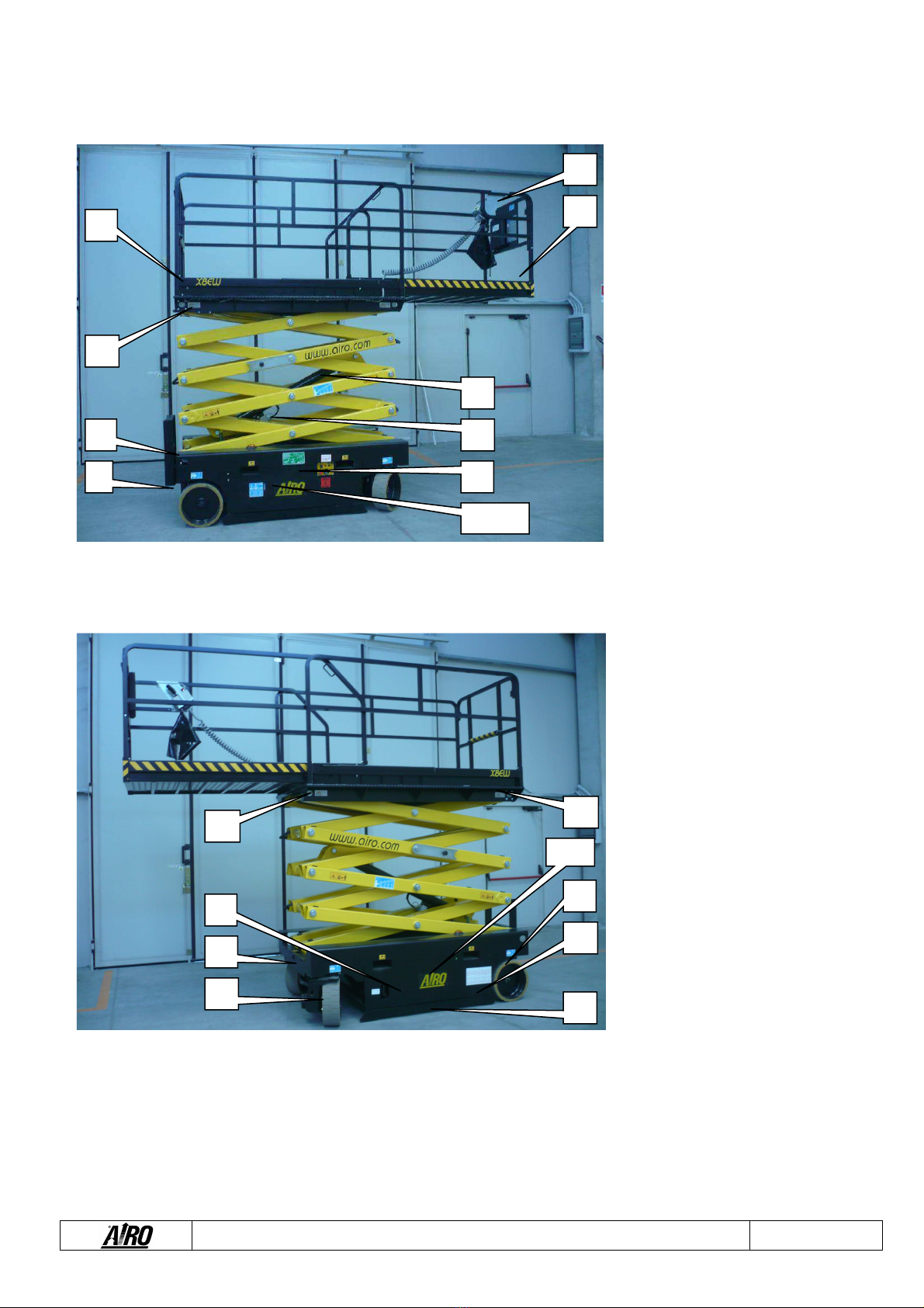
1.9 Loc tion of m in components
1-1: Right view
A.
Platform control panel
B. Bubble level (optional) for visual check
of platform levelling
C. Lifting cylinder
D. Lowering control valve
E. Ground control panel
F. Electric control unit and inclinometer
G. Tank
H. Electric pump
I. Manual device for emergency lowering
J. Platform height control M1
microswitch
K. Electronic board of platform overload
controller
L. 230V socket (optional)
M. Overload controller sensors
N. Batteries
O. Battery charger
P. Parking brakes
Q. MPT1 and MPT2 microswitches to
control the position of the pot-hole
guards
R. Hydraulic traction motors
S. Steering cylinder
T. Bipolar power connector
U. Pot-hole guards
1-2: Left view
A
B
L
C
D
J
I
P
R
E
F G H
Q
K
M
M
N O
S
T
U
Use and Main enance Manual - X Series Page 12
2. TECHNICAL FEATURES OF STANDARD MACHINES
THE TECHNICAL FEATURES OF THE PRODUCTS IN THE FOLLOWING PAGES CAN BE MODIFIED
WITHOUT PRIOR NOTICE
2.1 X8EN Model
X8EN
Maximum working height
8.3
m
Maximum platform height
6.3
m
Ground clearance
(pot
-
hole guards lifted)
100
mm
Ground clearance (pot
-
hole guards lowered)
15
mm
Platform height for safety speed activation
1.8
m
Internal steering radius
0
m
External steering radius
2.28
m
Maximum capacity (m)
400
kg
Max. number of peo
ple on the platform (n)
–
indoors
3
Tool and material weight (me) **
–
indoors
160
kg
Max. number of people on the platform (n)
–
outdoors
-
Tool and material weight (me) **
–
outdoors
-
Maximum deck extension
1.5
m
Maximum capacity on deck extension
400
kg
Maximum amount of people on deck extension
3
Maximum drive height
Max
Maximum platform dimensions (extended)
0.89 x 3.75
m
Max. hydraulic pressure
230
bar
Max. pressure of lifting circuit
160
bar
Min
. pressure of braking circuit
60÷70
bar
Tyre dimensions
Ø410 x 150
mm
Type of tyres
Cushion soft
Transport dimensions with removable guard rails installed *
0.89x2.4x2.23
m
Transport dimensions with removable guard rails not installed *
0.89x2.4x1
.28
m
Transport dimensions with guard rails folded down (optional) *
0.89x2.4x1.73
m
Machine weight (unloaded)
2000
kg
St bility limit:
Longitudinal inclination
3
°
Transversal inclination
2
°
Maximum wind speed
0
m/s
Max. load per wheel
120
0
Kg
Perform nce:
Battery capacity and voltage
4 x 6 / 200
V/Ah
Battery weight
4 x 32
kg
Single
-
phase battery charger
24 / 25
V/A
Max. current absorbed by the battery charger
12
A
Electric pump power
3
kW
Max. absorbed current
160
A
Max.
drive speed
3
km/h
Safety drive speed
0.6
km/h
Lowering/lifting time (unloaded)
47 / 47
Sec.
Oil tank capacity
30
Lt.
Gradeability
26
%
Max. operating temperature
+50
C
Min. operating temperature
-
15
C
( * ) removing the ladder, the machine overall dimensions are further reduced (length = 2.25 m)
( ** ) me = m – (n x 80)

Use and Main enance Manual - X Series Page 13
1) from the ground with gu rd r ils removed
2) from the ground with gu rd r ils folded down
(option l)

Use and Main enance Manual - X Series Page 14
2.2 X10EW - X10EW-WIND Model
Dimensions: X10EW-WIND X10EW
Maximum working height
10.2
10.2
m
Maximum platform height
8.2
8.2
m
Ground clearance (pot
-
hole guards li
fted)
100
100
mm
Ground clearance (pot
-
hole guards lowered)
15
15
mm
Platform height for safety speed activation
2.1
2.1
m
Internal steering radius
0
0
m
External steering radius
2.43
2.43
m
Maximum capacity (m)
500
500
kg
Max. number of
people on the platform (n)
–
indoors
3
3
Tool and material weight (me) **
–
indoors
260
260
kg
Max. number of people on the platform (n)
–
outdoors
1
-
Tool and material weight (me) **
–
outdoors
420
-
kg
Maximum deck extension
1.
5
1.5
m
Maximum capacity on deck extension
500
500
kg
Max. number of people on deck extension
–
indoors
3
3
Max. number of people on deck extension
–
outdoors
1
-
Maximum drive height
Max.
Max.
Maximum platform dimensions (extended)
1.2 x 3.75
1.2 x 3.75
m
Max. hydraulic pressure
230
230
bar
Max. pressure of lifting circuit
240
240
bar
Min. pressure of braking circuit
60÷70
60÷70
bar
Tyre dimensions
Ø410 x 150
Ø410 x 150
mm
Type of tyres
Cushion soft
Cushion soft
Transport dimensio
ns with removable guard rails installed *
1.2x2.4x2.36
1.2x2.4x2.36
m
Transport dimensions with removable guard rails not installed *
1.2x2.4x1.42
1.2x2.4x1.42
m
Transport dimensions with guard rails folded down (optional) *
1.2x2.4x1.86
1.2x2.4x1.86
m
Machine weight (unloaded)
2850
2350
kg
St bility limit:
Longitudinal inclination
3
3
°
Transversal inclination
2
2
°
Maximum wind speed
12.5
0
m/s
Max. load per wheel
1680
1380
Kg
Perform nce:
Battery capacity and voltage
4x6 / 200
4x6
/ 200
V/Ah
Battery weight
4x32
4x32
kg
Single
-
phase battery charger
24/25
24 / 25
V/A
Max. current absorbed by the battery charger
12
12
A
Electric pump power
3
3
kW
Max. absorbed current
160
160
A
Max. drive speed
3
3
km/h
Safety drive spee
d
0.6
0.6
km/h
Lowering/lifting time (unloaded)
47 / 47
47 / 47
Sec.
Oil tank capacity
30
30
Lt.
Gradeability
18
25
%
Max. operating temperature
+50
+50
C
Min. operating temperature
-
15
-
15
C
( * ) removing the ladder, the machine overall dimensions are further reduced (length = 2.25 m)
( ** ) me = m – (n x 80)

Use and Main enance Manual - X Series Page 15
1) from the ground with gu rd r ils removed
2) from the ground with gu rd r ils folded
down (option l)

Use and Main enance Manual - X Series Page 16
2.3 X10EN Model
Dimensions: X10EN
Maximum working height
10.2
m
Maximum platform height
8.2
m
Ground clearance (pot
-
hole guards lifted)
100
mm
Ground clearance (pot
-
hole guar
ds lowered)
15
mm
Platform height for safety speed activation
2.1
m
Internal steering radius
0
m
External steering radius
2.28
m
Maximum capacity (m)
400
kg
Max. number of people on the platform (n)
–
indoors
3
Tool and material wei
ght (me) **
–
indoors
160
kg
Max. number of people on the platform (n)
–
outdoors
-
Tool and material weight (me) **
–
outdoors
-
Maximum deck extension
1.5
m
Maximum capacity on deck extension
400
kg
Max. number of people on deck ext
ension
–
indoors
3
Max. number of people on deck extension
–
outdoors
-
Maximum drive height
Max.
Maximum platform dimensions (extended)
0.89 x 3.75
m
Max. hydraulic pressure
230
bar
Max. pressure of lifting circuit
210
bar
Min. pressure of
braking circuit
60÷70
bar
Tyre dimensions
Ø410 x 150
mm
Type of tyres
Cushion soft
Transport dimensions with removable guard rails installed *
0.89x2.4x2.42
m
Transport dimensions with removable guard rails not installed *
0.89x2.4x1.48
m
Transp
ort dimensions with guard rails folded down (optional) *
0.89x2.4x2.42
m
Machine weight (unloaded)
2750
kg
St bility limit:
Longitudinal inclination
3
°
Transversal inclination
2
°
Maximum wind speed
0
m/s
Max. load per wheel
1650
Kg
Perform
nce:
Battery capacity and voltage
4 x 6 / 200
V/Ah
Battery weight
4 x 32
kg
Single
-
phase battery charger
24 / 25
V/A
Max. current absorbed by the battery charger
12
A
Electric pump power
3
kW
Max. absorbed current
160
A
Max. drive speed
3
km/h
Safety drive speed
0.6
km/h
Lowering/lifting time (unloaded)
47 / 47
Sec.
Oil tank capacity
30
Lt.
Gradeability
20
%
Max. operating temperature
+50
C
Min. operating temperature
-
15
C
( * ) removing the ladder, the machine overall dimensions are further reduced (length = 2.25 m)
( ** ) me = m – (n x 80)
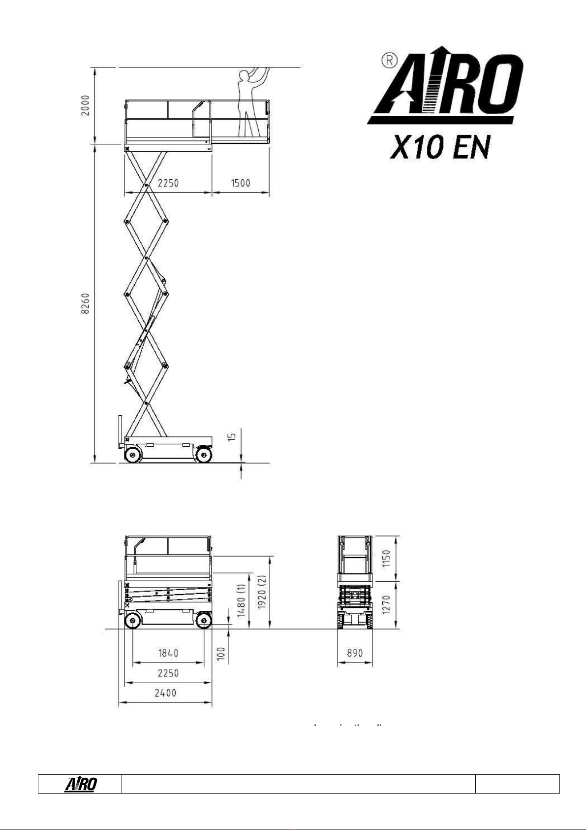
Use and Main enance Manual - X Series Page 17
1) from the ground with gu rd r ils removed
2) from the ground with gu rd r ils folded
down (option l)

Use and Main enance Manual - X Series Page 18
2.4 X12EW - X12EW-WIND Model
Dimensions: X12EW-WIND X12EW
Maximum working height
12.1
12.1
m
Maximum platform height
10.1
10.1
m
Ground clearance (pot
-
hole guards lifted)
100
1
00
mm
Ground clearance (pot
-
hole guards lowered)
15
15
mm
Platform height for safety speed activation
2.5
2.5
m
Internal steering radius
0
0
m
External steering radius
2.43
2.43
m
Maximum capacity (m)
300
450
kg
Max. number of people on
the platform (n)
–
indoors
3
3
Tool and material weight (me) **
–
indoors
60
210
kg
Max. number of people on the platform (n)
–
outdoors
1
-
Tool and material weight (me) **
–
outdoors
220
-
kg
Maximum deck extension
1.5
1.5
m
Maximum capacity on deck extension
300
450
kg
Max. number of people on deck extension
–
indoors
3
3
Max. number of people on deck extension
–
outdoors
1
-
Maximum drive height
Max.
Max.
Maximum platform dimensions (extended)
1.2 x 3.
75
1.2 x 3.75
m
Max. hydraulic pressure
230
230
bar
Max. pressure of lifting circuit
160
170
bar
Min. pressure of braking circuit
60÷70
60÷70
bar
Tyre dimensions
Ø410 x 150
Ø410 x 150
mm
Type of tyres
Cushion soft
Cushion soft
Transport dimens
ions with removable guard rails installed *
1.2x2.4x2.48
1.2x2.4x2.48
m
Transport dimensions with removable guard rails not installed *
1.2x2.4x1.54
1.2x2.4x1.54
m
Transport dimensions with guard rails folded down (optional) *
1.2x2.4x1.98
1.2x2.4x1.98
m
Machine weight (unloaded)
3320
2820
kg
St bility limit:
Longitudinal inclination
3
3
°
Transversal inclination
1.5
2
°
Maximum wind speed
12.5
0
m/s
Max. load per wheel
1950
1710
Kg
Perform nce:
Battery capacity and voltage
4x6 / 280
4x6 / 280
V/Ah
Battery weight
4x47
4x47
kg
Single
-
phase battery charger
24 / 25
24 / 25
V/A
Max. current absorbed by the battery charger
12
12
A
Electric pump power
4
4
kW
Max. absorbed current
200
200
A
Max. drive speed
3
3
km/h
Safety driv
e speed
0.6
0.6
km/h
Lowering/lifting time (unloaded)
70 / 70
70 / 70
Sec.
Oil tank capacity
30
30
Lt.
Gradeability
23
26
%
Max. operating temperature
+50
+50
C
Min. operating temperature
-
15
-
15
C
( * ) removing the ladder, the machine overall dimensions are further reduced (length = 2.25 m)
( ** ) me = m – (n x 80)

Use and Main enance Manual - X Series Page 19
1) from the ground with gu rd r ils removed
2) from the ground with gu rd r ils folded
down (opt
ion l)

Use and Main enance Manual - X Series Page 20
2.5 X12EN Model
Dimensions: X12EN
Maximum working height
12.1
m
Maximum platform height
10.1
m
Ground clearance (pot
-
hole guards lifted)
100
mm
Ground clearance (pot
-
h
ole guards lowered)
15
mm
Platform height for safety speed activation
2.5
m
Internal steering radius
0
m
External steering radius
2.28
m
Maximum capacity (m)
300
kg
Max. number of people on the platform (n)
–
indoors
3
Tool an
d material weight (me) **
–
indoors
60
kg
Max. number of people on the platform (n)
–
outdoors
-
Tool and material weight (me) **
–
outdoors
-
Maximum deck extension
1.5
m
Maximum capacity on deck extension
300
kg
Max. number
of people on deck extension
–
indoors
3
Max. number of people on deck extension
–
outdoors
-
Maximum drive height
Max.
m
Maximum platform dimensions (extended)
0.89 x 3.75
m
Max. hydraulic pressure
230
bar
Max. pressure of lifting circuit
160
b
ar
Min. pressure of braking circuit
60÷70
bar
Tyre dimensions
Ø410 x 150
mm
Type of tyres
Cushion soft
Transport dimensions with removable guard rails installed *
0.89x2.4x2.54
m
Transport dimensions with removable guard rails not installed *
0.
89x2.4x1.6
m
Transport dimensions with guard rails folded down (optional) *
0.89x2.4x2.04
m
Machine weight (unloaded)
3430
kg
St bility limit:
Longitudinal inclination
3
°
Transversal inclination
1.2
°
Maximum wind speed
0
m/s
Max. load per
wheel
2020
Kg
Perform nce:
Battery capacity and voltage
4x6 / 280
V/Ah
Battery weight
4x47
kg
Single
-
phase battery charger
24 / 25
V/A
Max. current absorbed by the battery charger
12
A
Electric pump power
4
kW
Max. absorbed current
200
A
M
ax. drive speed
3
km/h
Safety drive speed
0.6
km/h
Lowering/lifting time (unloaded)
70 / 70
Sec.
Oil tank capacity
30
Lt.
Gradeability
23
%
Max. operating temperature
+50
C
Min. operating temperature
-
15
C
( * ) removing the ladder, the machine overall dimensions are further reduced (length = 2.25 m)
( ** ) me = m – (n x 80)
This manual suits for next models
8
Table of contents
Popular Scissor Lift manuals by other brands


ALMAC
ALMAC Athena 870-BL EVO TRANSLATION OF ORIGINAL INSTRUCTIONS

Bike-Lift
Bike-Lift TWIN-ARMS MTA 516 Use and maintenance manual

LGMG
LGMG AS1932 Operation and safety manual

Upright
Upright X26 Series Operator's manual

TradeQuip
TradeQuip 6006 owner's manual

Hy-Brid Lifts
Hy-Brid Lifts III Series Operation & safety manual

GMG
GMG 1330-ED Operator's manual

Kleton
Kleton MJ519 instruction manual

Upright
Upright SL-26 Operator's manual

MAHA
MAHA TWIN F IV 3.0 Series Original operating instructions

Oshkosh Corporation
Oshkosh Corporation JLG ES2632 Operation and safety manual

Presto Lifts
Presto Lifts XP24-3 Series Installation, operation and service manual