Upright MX15 User manual

USA
TEL: (1) 800-926-5438 or (1) 559-662-3900
FAX: (1) 559-673-6184
Parts FAX: (1) 800-669-9884
801 South Pine Street
Madera, California 93637
http://www.upright.com
EUROPE
TEL: +353 1 620 9300
FAX: +353 1 620 9301
Unit S1, Park West Industrial Park
Friel Avenue
Nangor Road
Dublin 12, Ireland
LOCAL DISTRIBUTOR:
P/N 060570-008
06-02
Operator Manual
MX15 / MX19
SERIAL NO. 20000 to Current
WARNING
All personnel shall carefully read, understand and follow all safety rules,
operating instructions, and the Scaffold Industry Association’s
MANUAL OF RESPONSIBILITIES of ANSI A92.6-1999 before performing
maintenance on or operating any UpRight Aerial Work Platform.
P/N 060570-008

Call Toll Free in U.S.A.
1-800-926-LIFT
UpRight, Inc.
801 South Pine Street
Madera, California 93637
TEL: 559-662-3900
FAX: 559-673-6184
PA R T S : 1 - 8 8 8 - U R - PA R T S
PARTS FAX: 1-800-669-9884
UpRight
Unit S1, Park West Industrial Park
Friel Avenue
Nangor Road
Dublin 12, Ireland
TEL: +353 1 620 9300
FAX: +353 1 620 9301
1775 PARK ST. SELMA CALIFORNIA 93662 USA
Model:______________ Ser al number:_____________
GVW: __________lbs. Mfg. date:_ __________
Occupants and equ pment must not exceed the rated workload
_____lbs. Rated number of occupants: _____
Max mum platform he ght: ______ft.
Nom nal system voltage: ______vdc
Max mum wheel and/or outr gger load: _____lbs.
Th s mach ne s manufactured to comply w th ANSI A92.6-1999.
CAUTION: CONSULT OPERATOR’S MANUAL BEFORE USE.
THIS PLATFORM IS NOT ELECTRICALLY INSULATED
When contacting UpRight for service or parts information, be sure to include the MODEL and SERIAL NUMBERS
from the equipment nameplate. Should the nameplate be missing, the SERIAL NUMBER is also stamped on top of the
chassis above the front axle pivot.
MX15 / MX19
Serial Number 20000 – Current
Stamped Serial Number
Call Toll Free in U.S.A.
1-800-926-LIFT

Page 16 060570-008 MX15 / MX19 - Operator Manual
Specifications
S
PECIFICATIONS
*Specifications are subject to change without notice. Hot weather or heavy use may affect performance.
Refer to the Parts Manual and the Service Manual for complete parts and service information.
The MX15/19 meets or exceeds all applicable requirements of OSHA and ANSI A92.6-1999.
ITEM MX15 MX19
Platform Size (Inside minimum)
Standard w/Deck 0,72 m x 2,54 m (28.5 in. x 100 in.) 0,72 m x 2,54 m (28.5 in. x 100 in.)
Maximum Platform Capacity
Standard w/Deck Extension 250 kg (550 Lbs.) 227 kg (500 Lbs.)
Maximum Number of Occupants
Standard w/Deck Extension 2 People 2 People
on Extension 1 Person 1 Person
Height
Working Height 6,4 m (21 ft.) 7,62 m (25 ft.)
Maximum Platform Height 4,57 m (15 ft.) 5,8 m (19 ft.)
Maximum Drivable Height 4,57 m (15 ft.) 5,8 m (19 ft.)
Dimensions
Weight 1343 kg (2960 Lbs.) 1465 kg (3230 Lbs.)
Overall Width 760 mm (30 in.) 760 mm (30 in.)
Overall Height (Lowered) 1,89 m (74.5 in.) 2,01 m (79.25 in.)
Overall Length (Deck in) 1,75 m (68.75 in.) 1,75 m (68.75 in.)
Drive Speed
Platform Lowered 3,7 km/h (2.3 mph) 3,7 km/h (2.3 mph)
Platform Raised 1,0 km/h (0.62 mph) 1,0 km/h (0.62 mph)
Energy Source
24 V battery pack (4-220 A hour,
6 V batteries, min. wt. 26,3 kg [58 Lbs.]
each), 4 HP DC electric motor
24 V battery pack (4-220 A hour,
6 V batteries, min. wt. 26,3 kg [58 Lbs.]
each), 4 HP DC electric motor
System Voltage 24 V DC 24 V DC
Battery Charger 20 A, 110/220 VAC 20 A, 110/220 VAC
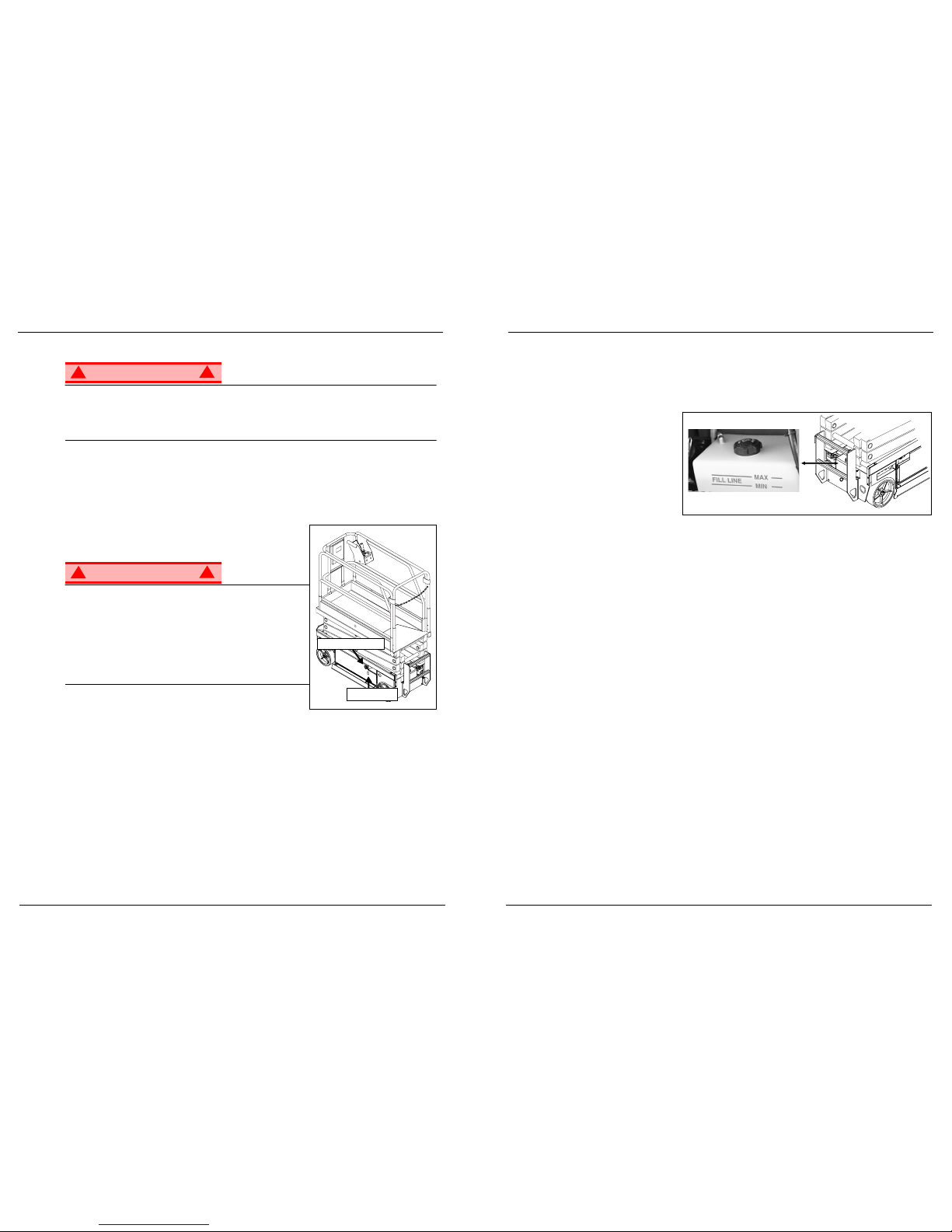
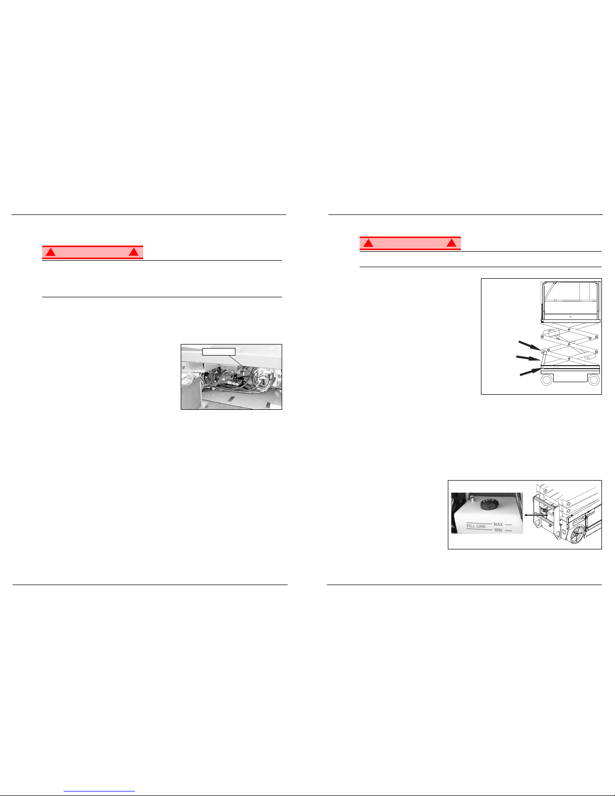
Hydraulic Reservoir Capacity 12,9 L (3.4 US gal.) 12,9 L (3.4 US gal.)
Maximum Hydraulic System Pressure 207 bar (3000 psi) 207 bar (3000 psi)
Hydraulic Fluid
Normal above 32° F [0° C] ISO #46 ISO #46
Low Temp. below 32° F [0° C] ISO #32 ISO #32
below 0° F [-17° C] ISO #15 ISO #15
Lift System One Single Stage Lift Cylinder One Single Stage Lift Cylinder
Drive Control Motor Control Motor Control
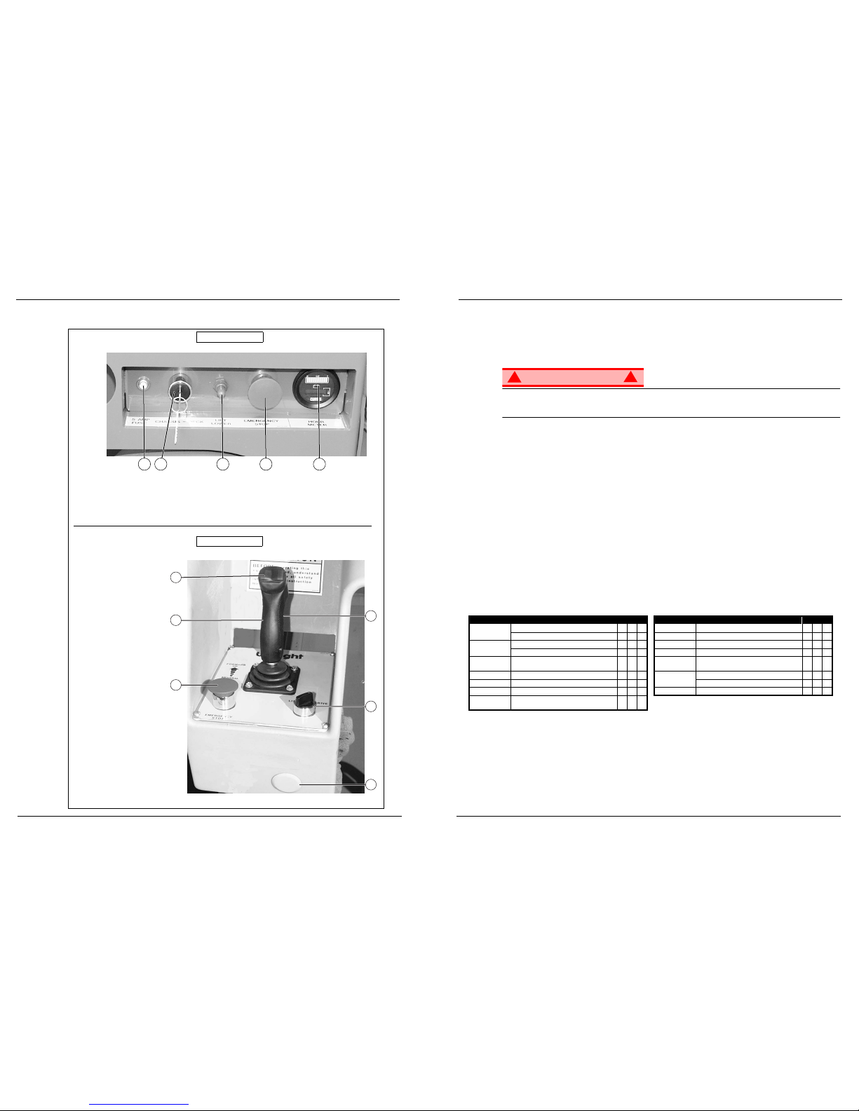
Control System
Control Handle with Interlock Switch,
Rotary Drive/Lift Switch, and Red
Mushroom Emergency Stop Switch
Control Handle with Interlock Switch,
Rotary Drive/Lift Switch, and Red
Mushroom Emergency Stop Switch
Drive System Dual Front Wheel Hydraulic Motors Dual Front Wheel Hydraulic Motors
Tires 30,5 cm (12 in.) diameter solid rubber,
Non-marking
30,5 cm (12 in.) diameter solid rubber,
Non-marking
Parking Brake Dual, Spring Applied, Hydraulic Release Dual, Spring Applied, Hydraulic Release
Turning Radius (inside) 150 mm (6 in.) Inside 150 mm (6 in.) Inside
Maximum Gradeability 29% (16°) 29% (16°)
Wheel Base 1,23 m (48.5 in.) 1,23 m (48.5 in.)
Guardrails 1,10 m (43 in.) 1,10 m (43 in.)
Toeboard 150 mm (6 in.) 150 mm (6 in.)
060570-008 MX15 / MX19 - Operator Manual Page 1
OPERATOR MANUAL
WARNING
All personnel shall carefully read, understand and follow all safety rules, operating instructions,
and the Scaffold Industry Association’s MANUAL OF RESPONSIBILITIES of ANSI A92.6-1999
before performing maintenance on or operating any UpRight Aerial Work Platform.
Safety Rules
Safety RulesSafety Rules
Safety Rules
•NEVER operate the machine without first surveying the work area for surface hazards such as holes, drop-offs, bumps,
curbs, or debris.
•NEVER operate the machine if all guardrails are not properly in place and secured with all fasteners properly torqued.
•ALWAYS close and secure the entrance after entering the platform.
•NEVER use ladders or scaffolding on the platform.
•NEVER exceed the maximum platform load. See “Specifications” on page 16.
•NEVER attach overhanging loads or increase platform size.
•LOOK up, down and around for overhead obstructions and electrical conductors.
•DISTRIBUTE all platform loads evenly on the platform.
•NEVER use damaged equipment. (Contact UpRight for instructions. See toll free phone number on inside back cover.)
•NEVER change operating or safety systems.
•INSPECT the machine thoroughly for cracked welds, loose or missing hardware, hydraulic leaks, damaged cables or
hoses, loose wire connections, and wheel bolts.
•NEVER climb down elevating assembly when the platform is elevated.
•IF ALARM SOUNDS while the platform is elevated, STOP, carefully lower the platform. Move the machine to a firm, level
surface.
•IN CASE OF EMERGENCY push the Emergency Stop button to cut power to all machine functions.
•NEVER perform service on the machine while the platform is elevated without blocking the elevating assembly.
•NEVER recharge batteries near sparks or open flame; batteries that are being charged emit explosive hydrogen gas.
•NEVER replace any component or part with anything other than original UpRight replacement parts without the manufac-
turer’s written consent.
•VERIFY that all labels are in place and legible before using.
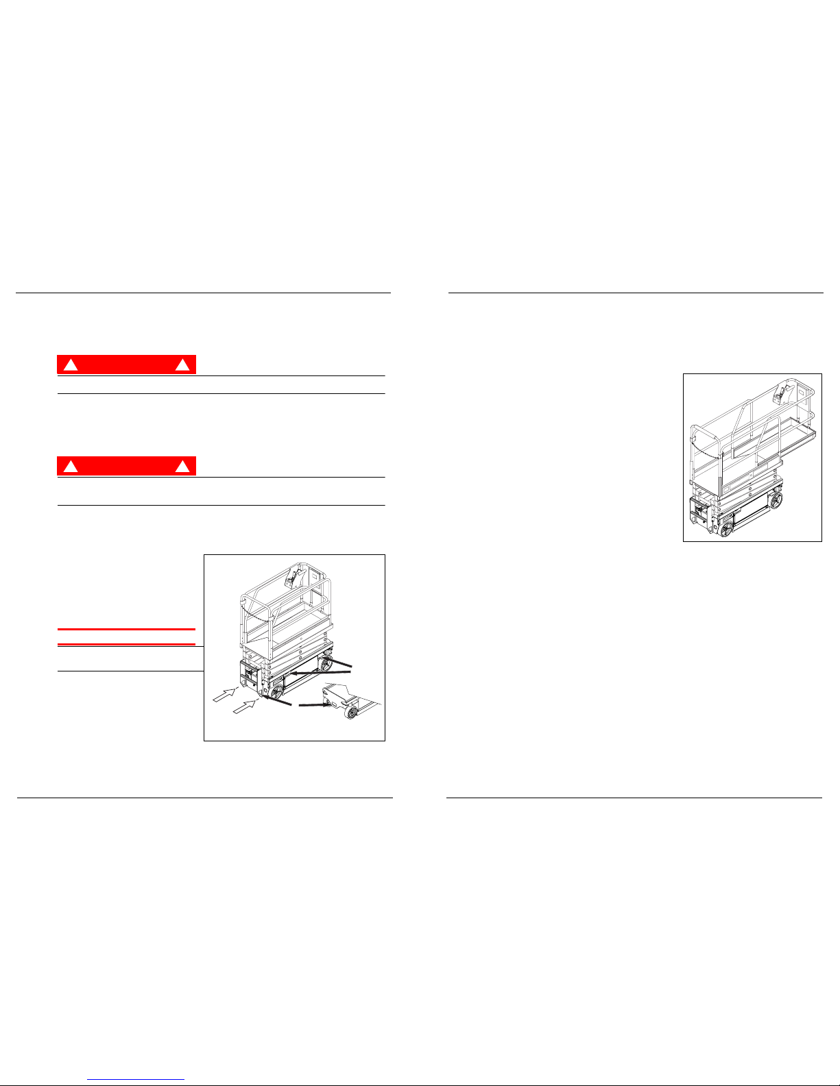
•NEVER tow the machine. Transport by truck or trailer only.
•AFTER USE, secure the machine against unauthorized use by turning the key switch off and removing the key.
California Proposition 65 Warning
Gasoline and diesel engine exhaust and some of their constituents are known to the State of California to
cause cancer, birth defects, and other reproductive harm.
Battery Posts, terminals and related accessories contain lead compounds, chemicals known to the State of
California to cause cancer and reproductive harm. Wash hands after handling.
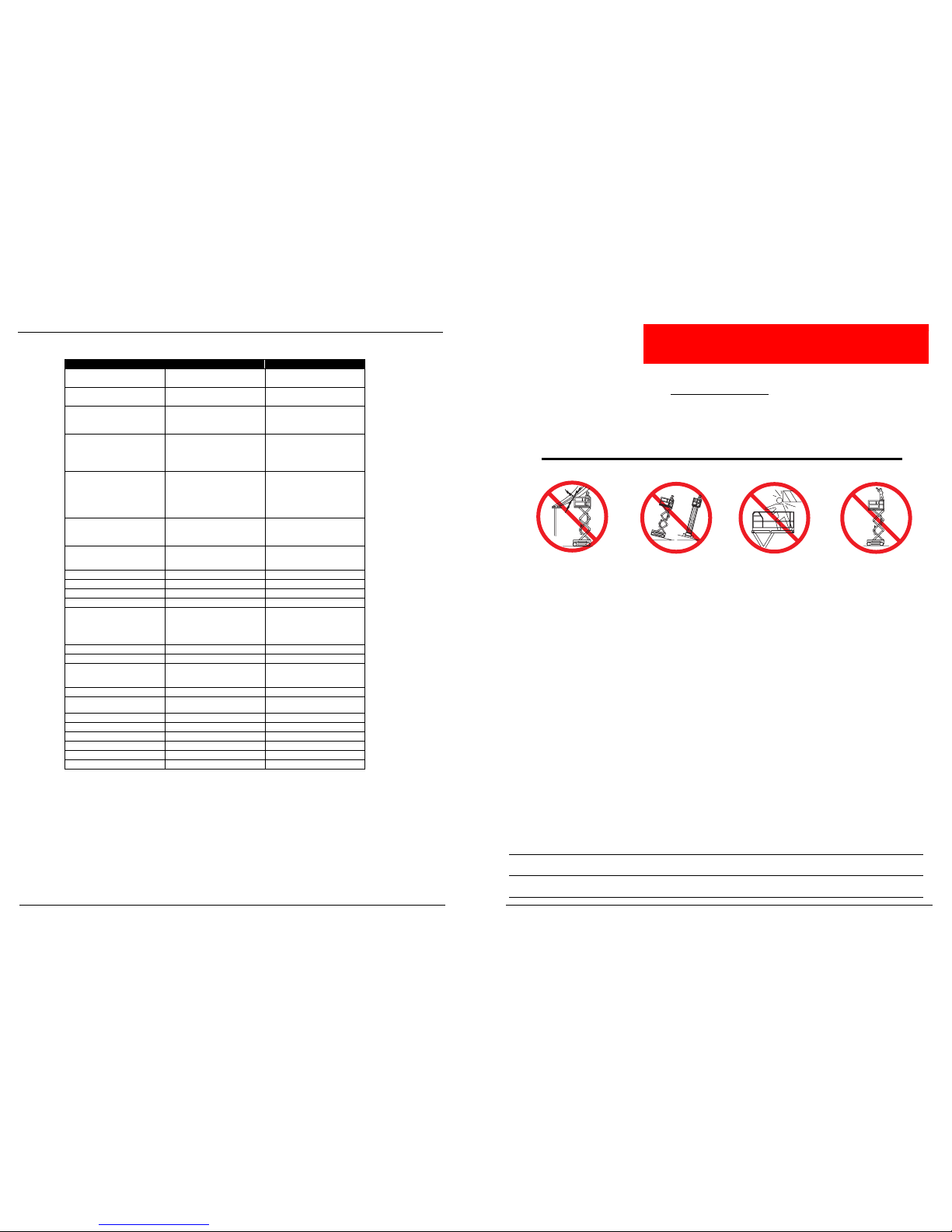
NEVER operate or drive with the
platform elevated unless on firm, level
surface.
NEVER position the platform without
first checking for overhead obstructions
or other hazards.
NEVER climb, stand or sit on the
platform guardrails or midrail.
Electrocution Hazard
Electrocution HazardElectrocution Hazard
Electrocution Hazard Tip Over Hazard
Tip Over HazardTip Over Hazard
Tip Over Hazard Collision Hazard
Collision HazardCollision Hazard
Collision Hazard Fall Hazard
Fall HazardFall Hazard
Fall Hazard
NEVER operate the machine within ten
(10) feet of power lines.
THIS MACHINE IS NOT INSULATED.

Page 2 060570-008 MX15 / MX19 - Operator Manual
C
ONTENTS
Introduction . . . . . . . . . . . . . . . . . . . . . . . . . . . . . . . . . . . . . . . . . . . . . . . . . . . . . . . . . . . . . . . . . . . . . . . . . 3
General Description . . . . . . . . . . . . . . . . . . . . . . . . . . . . . . . . . . . . . . . . . . . . . . . . . . . . . . . . . . . . . . . . . . 3
Controls and Indicators . . . . . . . . . . . . . . . . . . . . . . . . . . . . . . . . . . . . . . . . . . . . . . . . . . . . . . . . . . . . . . . 4
Pre-Operation Safety Inspection . . . . . . . . . . . . . . . . . . . . . . . . . . . . . . . . . . . . . . . . . . . . . . . . . . . . . . . . 5
System Function Inspection . . . . . . . . . . . . . . . . . . . . . . . . . . . . . . . . . . . . . . . . . . . . . . . . . . . . . . . . . . . 6
Operation . . . . . . . . . . . . . . . . . . . . . . . . . . . . . . . . . . . . . . . . . . . . . . . . . . . . . . . . . . . . . . . . . . . . . . . . . . . 7
Platform Extension . . . . . . . . . . . . . . . . . . . . . . . . . . . . . . . . . . . . . . . . . . . . . . . . . . . . . . . . . . . . . . . . . . . . . . . . . . . 7
Travel With the Platform Lowered . . . . . . . . . . . . . . . . . . . . . . . . . . . . . . . . . . . . . . . . . . . . . . . . . . . . . . . . . . . . . . . 7
Steering . . . . . . . . . . . . . . . . . . . . . . . . . . . . . . . . . . . . . . . . . . . . . . . . . . . . . . . . . . . . . . . . . . . . . . . . . . . . . . . . . . . 7
Elevating the Platform . . . . . . . . . . . . . . . . . . . . . . . . . . . . . . . . . . . . . . . . . . . . . . . . . . . . . . . . . . . . . . . . . . . . . . . . 8
Travel With the Platform Elevated . . . . . . . . . . . . . . . . . . . . . . . . . . . . . . . . . . . . . . . . . . . . . . . . . . . . . . . . . . . . . . . 8
Lowering the Platform . . . . . . . . . . . . . . . . . . . . . . . . . . . . . . . . . . . . . . . . . . . . . . . . . . . . . . . . . . . . . . . . . . . . . . . . 8
Emergency Lowering . . . . . . . . . . . . . . . . . . . . . . . . . . . . . . . . . . . . . . . . . . . . . . . . . . . . . . . . . . . . . . . . . . . . . . . . . 9
Parking Brake Release. . . . . . . . . . . . . . . . . . . . . . . . . . . . . . . . . . . . . . . . . . . . . . . . . . . . . . . . . . . . . . . . . . . . . . . . 9
After Use Each Day . . . . . . . . . . . . . . . . . . . . . . . . . . . . . . . . . . . . . . . . . . . . . . . . . . . . . . . . . . . . . . . . . . . . . . . . . . 9
Transporting the Work Platform . . . . . . . . . . . . . . . . . . . . . . . . . . . . . . . . . . . . . . . . . . . . . . . . . . . . . . . 10
By Crane . . . . . . . . . . . . . . . . . . . . . . . . . . . . . . . . . . . . . . . . . . . . . . . . . . . . . . . . . . . . . . . . . . . . . . . . . . . . . . . . . 10
By Forklift . . . . . . . . . . . . . . . . . . . . . . . . . . . . . . . . . . . . . . . . . . . . . . . . . . . . . . . . . . . . . . . . . . . . . . . . . . . . . . . . . 10
By Truck . . . . . . . . . . . . . . . . . . . . . . . . . . . . . . . . . . . . . . . . . . . . . . . . . . . . . . . . . . . . . . . . . . . . . . . . . . . . . . . . . . 10
Maintenance. . . . . . . . . . . . . . . . . . . . . . . . . . . . . . . . . . . . . . . . . . . . . . . . . . . . . . . . . . . . . . . . . . . . . . . . 11
Blocking The Elevating Assembly . . . . . . . . . . . . . . . . . . . . . . . . . . . . . . . . . . . . . . . . . . . . . . . . . . . . . . . . . . . . . . 11
Scissor Brace Installation . . . . . . . . . . . . . . . . . . . . . . . . . . . . . . . . . . . . . . . . . . . . . . . . . . . . . . . . . . . . . . . . . 11
Scissor Brace Storage . . . . . . . . . . . . . . . . . . . . . . . . . . . . . . . . . . . . . . . . . . . . . . . . . . . . . . . . . . . . . . . . . . . 11
Hydraulic Fluid . . . . . . . . . . . . . . . . . . . . . . . . . . . . . . . . . . . . . . . . . . . . . . . . . . . . . . . . . . . . . . . . . . . . . . . . . . . . . 11
Battery Maintenance . . . . . . . . . . . . . . . . . . . . . . . . . . . . . . . . . . . . . . . . . . . . . . . . . . . . . . . . . . . . . . . . . . . . . . . . 12
Battery Charging . . . . . . . . . . . . . . . . . . . . . . . . . . . . . . . . . . . . . . . . . . . . . . . . . . . . . . . . . . . . . . . . . . . . . . . . 12
Daily Inspection and Maintenance Schedule . . . . . . . . . . . . . . . . . . . . . . . . . . . . . . . . . . . . . . . . . . . . . 13
Daily Preventative Maintenance Checklist . . . . . . . . . . . . . . . . . . . . . . . . . . . . . . . . . . . . . . . . . . . . . . . 13
Labels . . . . . . . . . . . . . . . . . . . . . . . . . . . . . . . . . . . . . . . . . . . . . . . . . . . . . . . . . . . . . . . . . . . . . . . . . . . . . 14
Specifications . . . . . . . . . . . . . . . . . . . . . . . . . . . . . . . . . . . . . . . . . . . . . . . . . . . . . . . . . . . . . . . . . . . . . . 16
Labels
060570-008 MX15 / MX19 - Operator Manual Page 15
Figure 12: Safety Labels Locations
15
20
4
26
12
27
23
13
37
29
(INSIDE)
36 23
37 39 14 23
35
22
18
17
23
22
35
18
13
37
16
(INSIDE)
40
14
23
37
11
25 28
19

Page 14 060570-008 MX15 / MX19 - Operator Manual
Labels
L
ABELS
These labels shall be present and in good condition before operating the machine. Be sure to read, under-
stand and follow these labels when operating the machine.
11 066559-000
12 101251-000
13 066552-000
14 066553-003
15 066554-000
16 066555-000
17 066556-000
18 MX19 101250-000
18 MX15 101250-001
19 066558-000
20 101222-004
22 005221-000
23 014222-003-99
25 063255-001
26 010076-001
27 061220-002
28 MX15 101252-001
28 MX19 101252-002
29 061205-005
35 062562-001
36 066522-000
37 066556-001
39 068639-000
40 107051-000
4 066550-000
BATTERY
MAINTAIN BATTERY FLUID
AT RECOMMENDED LEVEL
TIP-OVER HAZARD
DANGER
!
BATTERIES ACT AS COUNTERWEIGHT
60 LBS OR MORE
EACH REPLACEMENT BATTERY SHALL WEIGH
CHARGER
BATTERY
WARNING
KEEP CLEAR OF
SCISSORS
BLOCK SCISSORS
BEFORE SERVICING
MAXIMUM DISTRIBUTED
PLATFORM LOAD 550 LBS.
OR TWO OCCUPANTS
MAXIMUM SIDE LOAD 100 LBS.
MAXIMUM DISTRIBUTED
PLATFORM LOAD 500 LBS.
OR TWO OCCUPANTS
MAXIMUM SIDE LOAD 100 LBS.
850 LBS.
1050 LBS.
Explosive gas is
generated when
charging batteries.
Do not expose to
sparks or flames.
Introduction
060570-008 MX15 / MX19 - Operator Manual Page 3
I
NTRODUCTION
This manual covers the application of the MX15 and MX19 Aerial Work Platforms. This manual must be
stored on the machine at all times.
Read, understand and follow all safety rules and operating instructions before attempting to operate the
machine.
G
ENERAL
D
ESCRIPTION
WARNING
!!
DO NOT use the machine without guardrails properly assembled and in place.
Figure 1: MX Series
1. Platform Controls
2. Manual Case
3. Deck Extension
4. Platform
5. Elevating
Assembly
6. Chassis
7. Batteries
8. Charger Outlet
Plug
9. Chassis Controls
10. Emergency
Lowering Valve
Knob
11. Hydraulic Fluid
Reservoir
2
1
3
4
5
7
6
8
9
10
11
10
11
Front

Page 4 060570-008 MX15 / MX19 - Operator Manual
Controls and Indicators
C
ONTROLS
AND
I
NDICATORS
Figure 2: Controls and Indicators
1
3
4
5
6
2
15
32 4
1 Circuit Breaker
2. Chassis Key Switch
3. Chassis Lift/Lower Switch
4. Chassis Emergency Stop Button
5. Hour Meter/Voltage Indicator
1. Steering Switch
2. Interlock Switch
(on front of Control Handle)
3. Control Handle
4. Platform Emergency Stop Switch
5. Lift Drive Selector Switch
6. Optional Horn Button Location
Platform Controls
Chassis Controls
Daily Inspection and Maintenance Schedule
060570-008 MX15 / MX19 - Operator Manual Page 13
D
AILY
I
NSPECTION
AND
M
AINTENANCE
S
CHEDULE
The Complete Inspection consists of periodic visual and operational checks, along with periodic minor
adjustments that assure proper performance. Daily inspection will prevent abnormal wear and prolong the
life of all systems. Perform the inspection and maintenance items daily. Inspection and maintenance shall
be performed by personnel who are trained and familiar with mechanical and electrical procedures.
WARNING
!!
Before performing preventative maintenance, familiarize yourself with the operation of the machine.
Always block the elevating assembly whenever it is necessary to perform maintenance while the
platform is elevated.
The daily preventative maintenance checklist has been designed for machine service and maintenance.
Please photocopy the Daily Preventative Maintenance Checklist and use the checklist when inspecting the
machine.
D
AILY
P
REVENTATIVE
M
AINTENANCE
C
HECKLIST
M
AINTENANCE
T
ABLE
K
EY
Y= Yes/Acceptable
N= No/Not Acceptable
R= Repaired/Acceptable
P
REVENTATIVE
M
AINTENANCE
R
EPORT
Date: ______________________________________
Owner: _____________________________________
Model No:___________________________________
Serial No: ___________________________________
Serviced By:_________________________________
COMPONENT INSPECTION OR SERVICES Y N R
Battery Check electrolyte level.
Check battery cable condition.
Chassis Check hoses for pinch or rubbing points.
Check welds for cracks.
Control Cable Check the exterior of the cable for pinching,
binding or wear.
Controller Check switch operation.
Drive Motors Check for operation and leaks.
Elevating Assembly Inspect for structural cracks.
Emergency
Lowering System
Operate the emergency lowering valve and check
for serviceability.
Entire Unit Check for and repair collision damage.
Hydraulic Fluid Check fluid level.
Hydraulic Pump Check for hose fitting leaks.
Hydraulic System Check for leaks.
Labels Check for peeling, missing, or unreadable labels &
replace.
Platform Deck and
Rails
Check welds for cracks.
Check condition of deck.
Tires Check for damage.
COMPONENT INSPECTION OR SERVICES Y N R

Page 12 060570-008 MX15 / MX19 - Operator Manual
Maintenance
B
ATTERY
M
AINTENANCE
WARNING
!!
Hazard of explosive gas mixture. Keep sparks, flame, and smoking material away from batteries.
Always wear safety glasses when working near batteries.
Battery fluid is highly corrosive. Thoroughly rinse away any spilled fluid with clean water.
Always replace batteries with UpRight batteries or manufacturer approved replacements weighing
26,3 kg (58 Lbs.) each.
• Check the battery fluid level daily, especially if the machine is being used in a warm, dry climate.
• If electrolyte level is lower than 10 mm (3/8in.) above the plates add distilled water only. DO NOT use
tap water with high mineral content, as it will shorten battery life.
• Keep the terminals and tops of the batteries clean.
• Refer to the Service Manual to extend battery life and for complete service instructions.
B
ATTERY
C
HARGING
Figure 11: Battery Charger
Charge the batteries at the end of each work shift or sooner if the
batteries have been discharged.
WARNING
!!
Charge the batteries in a well ventilated area.
Do not charge the batteries when the machine is near a source of
sparks or flames.
Permanent damage to the batteries will result if the batteries are not
immediately recharged after discharging.
Never leave the battery charger operating for more than two days.
Never disconnect the cables from the batteries when the charger is
operating.
Keep the charger dry.
1. Check the battery fluid level. If the battery fluid level is lower than
10 mm (3/8in.) above the plates add distilled water only.
2. Connect an extension cord (1,5 mm²[12 gauge] minimum conductor diameter; 15 m [50 ft.] maximum
length) to the charger plug located through a cutout at the left side of the chassis.
3. The charger turns on automatically after a short delay. There are three LED’s to indicate the state of
charge cycle.
• The first LED will blink until the batteries reach 50% state of charge, and then it will stop blinking and
stay ON.
• The second LED will blink until the batteries reach 75% state of charge, and then it will stop blinking
and stay ON.
• The third LED will blink until the batteries reach 100% state of charge, and then it will stop blinking
and stay ON.
• When the batteries are fully charged, all three LED’s will stay ON. The battery charger will automati-
cally turn off a short time after the batteries reach full charge.
NOTE: The battery charger circuit must be used with a GFI (Ground Fault Interrupt) outlet.
NOTE: DO NOT operate the machine while the charger is plugged in.
LED Indicator
Charger Outlet Plug
Pre-Operation Safety Inspection
060570-008 MX15 / MX19 - Operator Manual Page 5
P
RE
-O
PERATION
S
AFETY
I
NSPECTION
NOTE: Carefully read, understand and follow all safety rules, operating instructions, labels and the Scaffold Industry
Association’s MANUAL OF RESPONSIBILITIES of ANSI A92.6-1999. Perform the following steps each day before
use.
1. Open modules and inspect for damage, fluid leaks or missing parts.
Figure 3: Hydraulic Reservoir
2. Check the level of the hydrau-
lic fluid with the platform fully
lowered. The hydraulic reser-
voir is located at the rear of
the machine. The fluid level
should be visible through the
side of the reservoir, and
must be between the MIN
and MAX lines (see Figure 3).
Add hydraulic fluid if neces-
sary.
3. Check that fluid level in the batteries is correct (See “Battery Maintenance” on page 12).
4. Verify that batteries are charged.
5. Check that A.C. extension cord has been disconnected from the plug in the left Chassis Module, and
that the module doors are closed and locked.
6. Check that all guardrails are properly in place and secured with all fasteners properly torqued.
7. Inspect the machine thoroughly for cracked welds, loose or missing hardware, hydraulic leaks, damaged
cables or hoses, loose wire connections, and wheel bolts.

Page 6 060570-008 MX15 / MX19 - Operator Manual
System Function Inspection
S
YSTEM
F
UNCTION
I
NSPECTION
Refer to Figure 2 for the locations of various controls and indicators.
WARNING
!!
STAND CLEAR of the machine while performing the following checks.
Before operating the machine, survey the work area for surface hazards such as holes, drop-offs, bumps,
curbs, or debris.
LOOK up, down and around for overhead obstructions and electrical conductors.
Protect the control cable from possible damage while performing checks.
1. Move the machine, if necessary, to an unobstructed area to allow for full elevation.
2. Pull Chassis Emergency Stop Switch to the ON position.
3. Pull Platform Emergency Stop Switch to the ON position.
4. Turn and hold the Chassis Key Switch to CHASSIS.
5. Check Level Sensor operation:
Figure 4: Level Sensor Location
a. Open the door.
b. Push and hold the sensor off of level.
c. Push the Chassis Lift Switch to the UP position.
• The alarm should sound, and the platform should
not lift.
d. Close and latch the door.
6. Push the Chassis Lift/Lower Switch to the UP position
and raise the platform approximately 2,1 m (7 feet).
BLOCK THE ELEVATING ASSEMBLY AS DESCRIBED
ON page 11.
7. Visually inspect the elevating assembly, lift cylinder,
cables, and hoses for cracked welds and structural damage, loose hardware, hydraulic leaks, loose wire
connections, and erratic operation. Check for missing or loose parts.
8. Verify that the Depression Mechanism Supports have rotated into position under the machine.
REMOVE THE SCISSOR BRACE AS DESCRIBED ON page 11.
9. Push the Chassis Lift/Lower Switch to the UP position and fully elevate the platform. Partially lower the
platform by pushing Chassis Lift/Lower Switch to LOWER, and check for proper operation of the audible
lowering alarm.
10. Open the Emergency Lowering Valve (see Figure 3) by pulling the knob out to check for proper opera-
tion. When the platform is lowered, release the knob.
11. Push the Chassis Emergency Stop Switch to check for proper operation. All machine functions should
be disabled. Pull out the Chassis Emergency Stop Switch to resume.
12. Turn the Chassis Key Switch to DECK.
13. Check that route is clear of obstacles (persons, obstructions, holes, and drop-offs, bumps and debris),
is level, and is capable of supporting the wheel loads.
14. Mount the platform and properly close the entrance.
15. Turn the Drive/Lift Switch to DRIVE. While engaging the Interlock Switch, move the Control Handle to
FORWARD, then REVERSE, to check for speed control.
16. Push the Steering Switch RIGHT, then LEFT, to check for steering control.
17. Turn the Drive/Lift Switch to LIFT. Grasp the Control Handle, engaging the Interlock Switch, and push it
forward to check platform lift controls. Raise the platform to full elevation.
18. Pull back on the Control Handle. The platform should descend and the audible lowering alarm should
sound.
19. Push the Platform Emergency Stop Switch to check for proper operation. All machine functions should
be disabled. Pull out the Platform Emergency Stop Switch to resume.
Level Sensor
Maintenance
060570-008 MX15 / MX19 - Operator Manual Page 11
M
AINTENANCE
WARNING
!!
Never perform service while the platform is elevated without first blocking the elevating assembly.
DO NOT stand in the elevating assembly area while deploying or storing the brace.
Figure 9: Scissor Brace
B
LOCKING
T
HE
E
LEVATING
A
SSEMBLY
S
CISSOR
B
RACE
I
NSTALLATION
1. Park the machine on a firm, level surface. Com-
pletely unload the platform before installing the
Scissor Brace.
2. Verify that the Chassis and Platform Emergency
Stop Switches are ON by pulling each button
out.
3. Turn and hold the Chassis Key Switch to
CHASSIS. Push the Chassis Lift/Lower Switch
to UP and elevate the platform approximately
2,1 m (7ft.
).
4. Rotate the Scissor Brace to a vertical position.
5. Carefully lower the platform until the end of the Scissor Arm Weldment rests on the Brace.
S
CISSOR
B
RACE
S
TORAGE
1. While holding the Brace, slowly raise the platform using the Chassis Controls until the end of the Scissor
Arm Weldment clears the Scissor Brace.
2. Rotate the Scissor Brace forward to rest on the Chassis.
3. Push the Chassis Lift/Lower Switch to LOWER and completely lower the platform.
H
YDRAULIC
F
LUID
Figure 10: Hydraulic Reservoir
Check the level of the hydraulic
fluid with the platform fully lowered.
The hydraulic reservoir is located
at the rear of the machine. The fluid
level should be visible through the
side of the reservoir, and must be
between the MIN and MAX lines
(see Figure 10). Add hydraulic fluid
if necessary.
Scissor Arm
Weldment
Brace Installed
Brace Stowed

Page 10 060570-008 MX15 / MX19 - Operator Manual
Transporting the Machine
T
RANSPORTING
THE
M
ACHINE
B
Y
C
RANE
DANGER
! !
See specifications for weight of machine and be certain that crane is of adequate capacity to lift the
machine.
Secure the straps to Tie Down/Lift Points only.
B
Y
F
ORKLIFT
DANGER
! !
Forklifting is for transport only.
See specifications for weight of machine and be certain that forklift is of adequate capacity to lift the
machine.
Both the MX15 and MX19 may be forklifted from the rear end of the machine between the wheels.They
may also be forklifted from the side using the forklift pockets shown in Figure 8.
Figure 8: Transporting the Machine
B
Y
T
RUCK
Maneuver the machine into transport posi-
tion and chock the wheels. Secure the
machine to the transport vehicle by attach-
ing chains or straps of adequate load
capacity to the Tie Down/Lift Points.
CAUTION
Overtightening chains or straps attached to
the Tie Down/Lift Points may result in
damage to the machine.
Forklift Tie Down/Lift Points
Forklift
Pockets
Operation
060570-008 MX15 / MX19 - Operator Manual Page 7
O
PERATION
Before operating the machine, ensure that the Pre-Operation Safety Inspection and System Function
Inspection has been completed and that any deficiencies have been corrected. Never operate a dam-
aged or malfunctioning machine. The operator must be thoroughly trained on this machine.
P
LATFORM
E
XTENSION
Figure 5: Platform Extension
1. Mount the platform and properly close and secure the
entrance.
2. Depress the foot lever located at the rear of the platform
extension. Push the platform extension forward until the
pin engages the front stop.
3. To retract the platform extension, depress the foot lever
and pull the platform extension toward the rear of the
machine until the pin engages the rear stop.
T
RAVEL
W
ITH
THE
P
LATFORM
L
OWERED
1. Check that the route is clear of surface hazards such as
holes, drop-offs, bumps, curbs, or debris.
2. Check that the route is level, and is capable of support-
ing the wheel loads.
3. Verify that the Chassis Key Switch is turned to DECK
and Chassis Emergency Stop Switch is ON (pulled out).
4. Mount the platform and properly close the entrance.
5. Check clearances above, below, and to the sides of platform.
6. Pull the Platform Emergency Stop Switch out to the ON position.
7. Turn the Drive/Lift Switch to DRIVE.
8. Engage the Interlock Switch and move the Control Handle to FORWARD or REVERSE to travel in the
desired direction. The speed of the machine will vary depending on how far from center the Control Han-
dle is moved.
S
TEERING
1. Turn the Drive/Lift Switch to DRIVE.
2. While engaging the Interlock Switch, push the Steering Switch to RIGHT or LEFT to turn the wheels in
the desired direction. Observe the tires while maneuvering the machine to ensure proper direction.
NOTE: Steering is not self-centering. Wheels must be returned to the straight ahead position by operating the Steering
Switch.

Page 8 060570-008 MX15 / MX19 - Operator Manual
Operation
E
LEVATING
THE
P
LATFORM
1. Locate a firm, level surface.
2. Turn the Drive/Lift Switch to LIFT.
3. While engaging the Interlock Switch, push the Control Handle forward.
4. If the machine is not level the tilt alarm will sound and the machine will not lift or drive. If the tilt alarm
sounds the platform must be lowered and the machine moved to a firm, level surface before
attempting to elevate the platform.
NOTE: Depression Mechanism Supports will deploy automatically as the platform elevates and will retract after the
platform has been lowered completely and driven.
T
RAVEL
W
ITH
THE
P
LATFORM
E
LEVATED
NOTE: The machine will travel at reduced speed when the platform is elevated.
1. Check that the route is clear of surface hazards such as holes, drop-offs, bumps, curbs, or debris.
2. Check that the route is level, and is capable of supporting the wheel loads.
3. Check clearances above, below, and to the sides of platform.
4. Turn the Drive/Lift Switch to DRIVE.
5. Engage the Interlock Switch and move the Control Handle to FORWARD or REVERSE to travel in the
desired direction. The speed of the machine will vary depending on how far from center the Control
Handle is moved.
6. If the machine is not level the tilt alarm will sound and the machine will not lift or drive. If the tilt alarm
sounds the platform must be lowered and the machine moved to a firm, level surface before
attempting to elevate the platform.
L
OWERING
THE
P
LATFORM
1. Turn the Drive/Lift Switch to LIFT.
2. Check around the base of the platform to ensure that no one is in contact with the machine. Engage the
Interlock Switch and pull back on the Control Handle to lower the platform.
Operation
060570-008 MX15 / MX19 - Operator Manual Page 9
E
MERGENCY
L
OWERING
WARNING
!!
If the platform should fail to lower, NEVER climb down the elevating assembly.
Stand clear of the elevating assembly while operating the Emergency Lowering Valve Knob.
Figure 6: Emergency Lowering
The Emergency Lowering Valve Knob is located
beside the ladder at the rear of the machine.
1. Open the Emergency Lowering Valve by pulling
and holding the knob.
2. To close, release the knob. The platform will not
elevate if the Emergency Lowering Valve is
open.
P
ARKING
B
RAKE
R
ELEASE
Perform the following procedure only when the machine will not operate under its own power and it is nec-
essary to move the machine, or when winching onto a trailer to transport.
Figure 7: Parking Brake Release
1. To release the brakes, loosen the jam nut and bolt until the
brakes disengage the tires (Figure 7). The machine will now
roll when pushed or pulled.
2. To re-engage the brakes, tighten the bolt until the brakes
have fully engaged the tires. Secure the bolt with the jam nut.
Verify that the brakes have fully engaged the rear tires before
operating the machine by testing their ability to hold the
machine on a 29% (16°) grade.
WARNING
!!
Never tow faster than 0,3 m/sec. (1 ft./sec.).
Never operate the machine with the parking brakes released. Serious injury or damage could result.
A
FTER
U
SE
E
ACH
D
AY
1. Ensure that the platform is fully lowered.
2. Park the machine on a firm level surface, preferably under cover, secure against vandals, children and
unauthorized operation.
3. Turn the Chassis Key Switch to OFF and remove the key to prevent unauthorized operation.
Emergency
Lowering
Valve Knob
Hydraulic Fluid
Reservoir
Brake Release Bolt
Other manuals for MX15
9
This manual suits for next models
1
Table of contents
Other Upright Scissor Lift manuals

Upright
Upright TM12 User manual

Upright
Upright SL-26 User manual

Upright
Upright SL20 Series User manual

Upright
Upright SL-26 User manual

Upright
Upright X26 Ultra Narrow User manual

Upright
Upright LX31 User manual

Upright
Upright X26 Ultra Narrow User manual

Upright
Upright MX15 User manual

Upright
Upright MX Series Installation and user guide

Upright
Upright MX15 User manual