TIL AMS-6000 User manual

AMS-6000
AUDIO MODE SELECTOR
MAINTENANCE MANUAL
TiL Document No. 10RE427
Revision N/C
NOVEMBER 2012
Technisonic Industries Limited
240 Traders Boulevard, Mississauga, Ontario L4Z 1W7
Tel: (905) 890-2113 Fax: (905) 890-5338
www.til.ca
Copyright by Technisonic Industries Limited. All rights reserved.

i
REVISION HISTORY
[ 10RE427 ]
REV SECTION
PAGE DESCRIPTION DATE
EDITED
BY
N/C Original Issue NOV 2012 F.M.

ii

iii
INTRODUCTION
Thank you for choosing this product.
This manual provides information servicing and repairing:
the AUDIO MODE SELECTOR Model AMS-6000, P/N 031220-1.
Audience
This service manual is written for Service Technicians responsible for repairing of:
the AUDIO MODE SELECTOR Model AMS-6000
and comes with complete schematics and parts list.
Online Documentation
This document is also found in its PDF format at http://www.til.ca via our maintenance manual
subscription service.
Supporting Documents
•INSTALLATION AND OPERATING INSTRUCTIONS, TiL Document 03RE325.
For the latest document release, refer to the company website under AMS-6000.
Technisonic website http://www.til.ca
Link to the Publication Index for "Repair Manuals and Publications", the “Technical Information
and Service Bulletins” and the software/firmware history index (login required).
Getting Help
For assistance with any of the Technisonic products, contact Technisonic Customer Product
Service:
Technisonic Industries Limited
240 Traders Boulevard
Mississauga, Ontario L4Z 1W7
Phone: - 905-890-2113
Fax: - 905-890-5338
RELEASE NOTES
This document includes the following:
•MAINTENANCE MANUAL with schematics and parts list, TiL Document 10RE427.
This panel mounted audio mode selector device allows for installation of the multi-band TDFM-600/6000
into aircraft with only a single audio controller position available. It also provides for enhanced operation
of the TDFM-600/6000 series radios in installations where multiple audio controller positions are
available.
The AMS-6000 has two basic operating modes, "combined radio" and "separate radio" modes.
•In “combined” mode, transceivers can only be operated one band at a time, however, it does negate
the requirement to occupy up to three positions on the aircrafts audio controller when installing the
multi-band TDFM-600/6000 series radio.
•In “separate” mode, the AMS-6000 outputs separate sets of key lines and receive/transmit audio
lines to support up to three separate audio controller positions. The transmitter selection is made by
selecting the desired radio via the aircraft's audio controller.
The current software version is AMS5 from the date when this manual was printed. However, for the
latest software release, refer to the publication list under AMS-6000 for the software / firmware history
index (login required).

iv
ESD CAUTION
This unit contains static sensitive devices. Wear a grounded wrist strap and/or conductive
gloves when handling printed circuit boards.
FCC COMPLIANCE INFORMATION
WARNING: This device complies with Part 15 of the FCC Rules. Operation is subject to the
following two conditions: (1) this device may not cause harmful interference and (2) this
device must accept any interference received, including interference that may cause
undesired operation.
WARNING AND DISCLAIMER
Changes or modifications not expressly approved by Technisonic Industries could void the user’s
authority to operate the equipment.
This manual is designed to provide information about the AMS-6000. Every effort has been made to
make this manual as complete and accurate as possible.
WARRANTY INFORMATION
The Model AMS-6000 Audio Mode Selector is under warranty for one year from date of purchase.
Failed units caused by defective parts, or workmanship should be returned to:
Technisonic Industries Limited
240 Traders Boulevard
Mississauga, Ontario L4Z 1W7
Tel: (905) 890-2113
Fax: (905) 890-5338

TECHNISONIC INDUSTRIES LIMITED
www.til.ca
AMS-6000 Maintenance Manual TiL 10RE427
v
TABLE OF CONTENTS
Section Title Page
SECTION 1 THEORY OF OPERATION
1.1 INTRODUCTION ............................................................................................. 1-1
1.1.1 AMS-6000 Overview ...................................................................................... 1-2
1.1.2 AMS-6000 Modules ........................................................................................ 1-2
1.2 MICROCONTROLLER (MCU) BOARD ................................................................. 1-4
1.2.1 The MCU Rear Interface ................................................................................ 1-4
1.2.2 The MCU Front Interface ............................................................................... 1-4
1.2.3 The MCU (Microcontroller) ............................................................................ 1-5
1.3 FRONT PANEL ASSEMBLY .............................................................................. 1-6
1.3.1 Front Panel Board ........................................................................................... 1-6
1.3.2 Riser Assembly .............................................................................................. 1-6
SECTION 2 TROUBLESHOOTING AND MODULE REPLACEMENT
2.0 INTRODUCTION ............................................................................................. 2-1
2.1 ISOLATING PROBLEMS TO MODULES .............................................................. 2-1
2.2 MODULES REPLACEMENT PROCEDURE ............................................................. 2-1
2.2.1 Disassembling the AMS-6000 Unit ................................................................. 2-2
2.2.2 Removing the Front Panel Face Plate .............................................................. 2-3
2.2.3 Removing the Front Panel Chassis Plate .......................................................... 2-4
2.2.4 Removing the Chassis Screws and Chassis (Cover) ........................................... 2-6
2.2.5 Removing and separating the Assemblies ........................................................ 2-7
2.2.6 Soldered Assemblies .................................................................................... 2-9
2.2.7 Miscellaneous Hardware ............................................................................... 2-9
2.3 POST REPAIR TESTING ................................................................................... 2-9

TECHNISONIC INDUSTRIES LIMITED
www.til.ca
AMS-6000 Maintenance Manual TiL 10RE427
vi
Section Title Page
SECTION 3 FACTORY TEST PROCEDURES
3.0 FACTORY TEST PROCEDURES ......................................................................... 3-1
3.1 TEST PROCEDURE REQUIREMENTS .................................................................. 3-1
3.1.1 Equipment Required ..................................................................................... 3-1
3.1.2 Documentation Required ............................................................................... 3-1
3.2 PRODUCTION TEST SEQUENCE ....................................................................... 3-2
SECTION 4 SCHEMATICS and LAYOUTS
4.1 INTRODUCTION ............................................................................................. 4-1
4.2 SECTION ORGANIZATION ............................................................................... 4-1
4.2.1 Using This Section ....................................................................................... 4-1
4.2.2 Designated Figures Scheme ........................................................................... 4-1
4.3 DRAWING INDEX ........................................................................................... 4-3
4.4 DIAGRAMS SECTIONED BY MODULES ............................................................. 4-4
SCHEMATICS AND ARTWORK SECTION (Schematic followed by layout)
This section (Sectioned by Modules) .................................................................
Schematics and Layout ................................................................................... 4-A
SECTION 5 PARTS LIST
5.1 INTRODUCTION ............................................................................................. 5-1
5.2 BREAKDOWN OF THE AMS-6000 ..................................................................... 5-1
5.3 CONTENTS OF PARTS BREAKDOWN ................................................................ 5-1
5.3.1 Parts List Breakdown .................................................................................... 5-1
5.3.2 Parts List Enclosed in this Section .................................................................. 5-2
PARTS LIST SECTION
Parts List ......................................................................................................... 5-9
APPENDICES FOR THE AMS-6000 AUDIO MODE SELECTOR
A: Doc # SHI-14-01 AMS-6000 P/N 031220-x SOFTWARE/FIRMWARE HISTORY INDEX
B: Doc # 036357 AMS-6000 FINAL TEST PROCEDURE
C: Doc # 036358 AMS-6000 TEST DATA SHEET

TECHNISONIC INDUSTRIES LIMITED
www.til.ca
AMS-6000 Maintenance Manual TiL 10RE427
vii
LIST OF FIGURES
Figure Title Page
1.1 AMS-6000 Audio Mode Selector - Internal Modules .......................................... 1-2
1.2 AMS-6000 Block Diagram ............................................................................. 1-5
1.2 AMS-6000 MCU Block Schematic Diagram ..................................................... 1-6
2.1 AMS-6000 Audio Mode Selector - Exploded Diagram ........................................ 2-1
2.2.1A AMS-6000 Front View ................................................................................. 2-2
2.2.1B AMS-6000 Back View .................................................................................. 2-2
2.2.1C AMS-6000 Side Views ................................................................................. 2-2
2.2.2A Removing the Front Panel Face Plate .............................................................. 2-3
2.2.2B Front Panel Face Plate Removed .................................................................... 2-3
2.2.3A Removing the Front Panel Chassis Plate screws ............................................... 2-4
2.2.3B The Front Panel Face Plate and Chassis Plate Removed ..................................... 2-4
2.2.3C The Front Panel with Chassis Plate Removed ................................................... 2-4
2.2.4A Removing the Chassis .................................................................................. 2-5
2.2.4B The Front Panel Chassis Screws Removed ....................................................... 2-5
2.2.4C Assembly Modules Removed from Chassis (Back View) .................................... 2-6
2.2.4D Assembly Modules Removed from Chassis (Front View)r ................................... 2-6
2.2.4E Chassis (Cover) Removed (Top and Bottom View) ............................................. 2-6
2.2.5A Display, Front Panel Board (Front View) .......................................................... 2-7
2.2.5B MCU Board (Bottom View) ............................................................................ 2-7
2.2.5C Front Panel Board Removed from the MCU (Top View) ...................................... 2-8
2.2.5D Front Panel Board Removed from the MCU (Bottom View).................................. 2-8
3.1 Production Test Sequence ............................................................................. 3-2
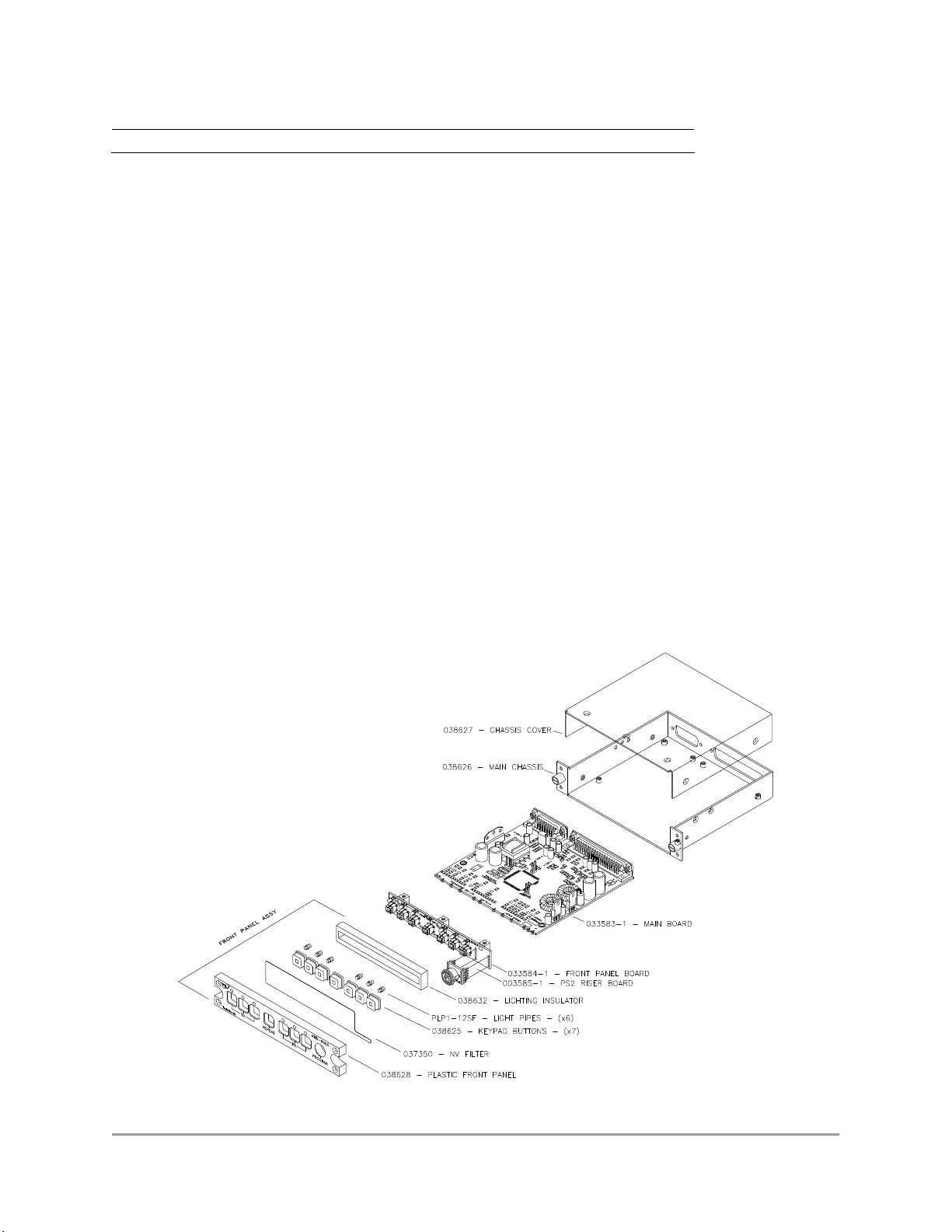
4.1 AMS-6000 Exploded View – Internal Modules ................................................. 4-2
5.1 AMS-6000 Audio Mode Selector - Internal Modules View .................................. 5-2
5.2 AMS-6000 Audio Mode Selector - Assembly Family Tree .................................. 5-3
LIST OF TABLES
Table Title Page
1.1 AMS-6000 Audio Mode Selector – Configuration Overview ............................... 1-4
1.2 MCU Sockets, Jumpers and Connectors .......................................................... 1-4
1.3 Front Panel Connectors ................................................................................. 1-5
4.1 AMS-6000 Audio Mode Selector – Configuration Overview ............................... 4-2
4.2 AMS-6000 Reference Table Schematic & Component Layout Sectioned by Modules
4-3
5.1 Index of Parts List Enclosed for the AMS-6000 ................................................ 5-2
5.2 Assembly Listing for the AMS-6000 Audio Mode Selector ................................. 5-4

TECHNISONIC INDUSTRIES LIMITED
www.til.ca
AMS-6000 Maintenance Manual TiL 10RE427
viii
LIST OF FUNCTIONAL,
SCHEMATIC AND COMPONMENT LAYOUT DIAGRAMS
Figure # Title Section
AMS-6000 AUDIO MODE SELECTOR FINAL ASSEMBLY
4.0 AMS-6000 Audio Mode Selector - Exploded View of Modules #032781 .............. 4A
4.1 AMS-6000 Audio Mode Selector - Block Diagram .............................................. 4A
Microcontroller (MCU) P/N 033583-1
4.1.0 Microcontroller (MCU) - Block Diagram ............................................................ 4-A1
4.1.1 Microcontroller (MCU) - Schematic Diagram, Rev J ........................................... 4-A1
4.1.1 Microcontroller (MCU) - Schematic Diagram, Rev H ........................................... 4-A1
4.1.1 Microcontroller (MCU) - Schematic Diagram, Rev G ........................................... 4-A1
4.1.1 Microcontroller (MCU) - Schematic Diagram, Rev F ........................................... 4-A1
4.1.1 Microcontroller (MCU) - Schematic Diagram, Rev E ........................................... 4-A1
4.1.1a Microcontroller (MCU) - Component Layout, Rev F ............................................ 4-A1
4.1.1a Microcontroller (MCU) - Component Layout, Rev E ............................................ 4-A1
Front Panel Board PN 033584-1
4.1.3 Front Panel Board - Schematic Diagram, Rev A ................................................. 4-A2
4.1.3 Front Panel Board - Schematic Diagram ........................................................... 4-A2
4.1.3a Front Panel Board - Component Layout, Rev C .................................................. 4-A2
4.1.3a Front Panel Board - Component Layout, Rev B .................................................. 4-A2
Riser Board PN 033585-1
4.1.3 Riser Board - Schematic Diagram .................................................................... 4-A3
4.1.3a Riser Board - Component Layout ..................................................................... 4-A3

TECHNISONIC INDUSTRIES LIMITED
www.til.ca
AMS-6000 Maintenance Manual TiL 10RE427
1-1
SECTION 1 – THEORY OF OPERATION
1.1 INTRODUCTION
The AMS-6000, Part Number 031220-1, is a panel mount Audio Mode Selector designed to
enhance the functionality of Technisonic TDFM-600/6000 series, Project 25 capable
airborne FM transceivers,
This panel mounted device allows for installation of the multi-band TDFM-600/6000 into
aircraft with only a single audio controller position available. It also provides for enhanced
operation of the TDFM-600/6000 series radios in installations where multiple audio
controller positions are available.
The AMS-6000 has two basic operating modes. These are "combined radio" and "separate
radio" modes.
Combined radio mode. The AMS-6000 combines the audio and key lines from the TDFM
600/6000 series transceiver and outputs them for delivery to a single position on an
audio controller. The transceivers can only be operated one band at a time, however, it
does negate the requirement to occupy up to three positions on the aircrafts audio
controller when installing the multi-band TDFM-600/6000 series radio.
Separate radio mode. The AMS-6000 can be configured to operate in "separate radio"
mode for Missions that require simultaneous operation on three bands. In this mode, the
AMS-6000 outputs separate sets of key lines and receive/transmit audio lines to support
up to three separate audio controller positions. In the "separate radio" mode, transmitter
selection is made by selecting the desired radio via the aircraft's audio controller.
When the AMS-6000 is operated in either of the "combined radio" or "single radio" modes,
the receive signal from each of the bands is annunciated by a receive LED on the AMS-
6000 front panel. In the "single radio" mode, the transmit selection/indication functions for
each band are enabled by push buttons on the face panel of the AMS-6000 with an LED
confirming the selected band. Inasmuch as the TDFM-600/6000 can only display
information regarding a single band at any given time, the AMS-6000 will enhance operator
awareness by providing receive indication on up to three bands simultaneously.
Additionally, the AMS-6000 provides support for simulcast for up to three bands and cross
band repeat in either the "combined radio" or "separate radio" modes.
This section describes the theory of operation of the AMS-6000 Audio Mode Selector. It
first shows the basic system architecture and then describes the operation of each
component or module separately. The schematic diagrams and layouts mentioned here are
available in section 4.

TECHNISONIC INDUSTRIES LIMITED
www.til.ca
AMS-6000 Maintenance Manual TiL 10RE427
1-2
1.1.1 AMS-6000 Overview
The AMS-6000 is divided into three physical functional blocks. These divisions are shown in
the block diagram of Figure 1.1 below. Note that the schematic diagrams for each module
are provided in section 4. The theory of operation will refer to these schematics, as well as
to the block diagrams given in this section.
FIGURE 1.1 AMS-6000 – Block Diagram
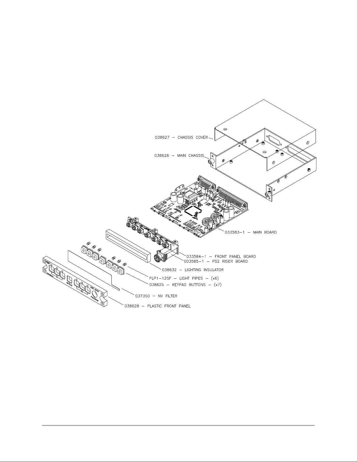
1.1.2 AMS-6000 Modules
The AMS-6000 Audio Mode Selector - Internal Modules can be seen in Figure 1.2 below.
The AMS-6000 assembly breakdown is described below.
Final Assembly: Part Number (P/N) 031220-1
Microcontroller Board (MCU):
Part Number (P/N) 033583-1 is described in section 1.2.
Front Panel Board:
Part Number (P/N) 033584-1 is described in section 1.3.1.
Riser Board:
Part Number (P/N) 003585-1 is described in section 1.3.2.
TECHNISONIC INDUSTRIES LIMITED
www.til.ca
AMS-6000 Maintenance Manual TiL 10RE427
1-3
FIGURE 1.2 AMS-6000 Audio Mode Selector - Internal Modules

TECHNISONIC INDUSTRIES LIMITED
www.til.ca
AMS-6000 Maintenance Manual TiL 10RE427
1-4
1.2 MICROCONTROLLER (MCU) BOARD
The AMS-6000 MCU Part Number P/N 033583-1
Refer to: The MCU board, Schematic Diagram, Figure 4.1.1
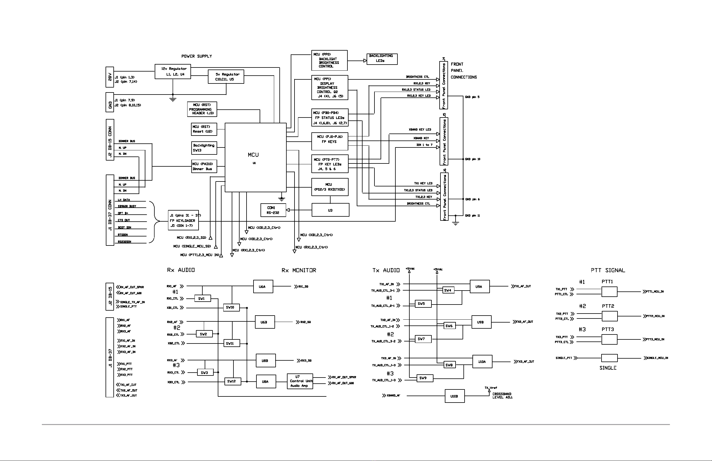
The MCU board controls the Audio Mode Selector unit and has major components as shown
in the functional schematic block diagram Figure 1.3. The board can be divided into five
sections: the MBU Power Supply, MCU control, Rx Audio/Monitor, Tx Audio, and PTT
Signal.
MCU Connectors
J1 REAR DB-37-pin CONN 37-pins
J2 REAR DB-15-pin CONN 15-pins
J3 PROGRAMMING HEADER 6 pins
CON1 RS-232 3 pins
J4 FRONT PANEL CONNECTIONS 11-pins
J5 FRONT PANEL CONNECTIONS 11-pins
J6 FRONT PANEL CONNECTIONS 11-pins
TABLE 1.1 MCU Board Connectors
1.2.1 The MCU Rear Interface
The rear connector J2 and J1 pin assignments are shown in the Installation and Operating
Instructions Document # 03RE325 section 3 in Tables 3-1 and 3-2 respectively.
1.2.2 The MCU Front Interface
The MCU connects to the Front Panel via connectors J5, and soldered connectors J4 and
J6. See Table 1.2 below.
pin J5
pin J4 pin J6
1 DIN1 LH Data 1 Rx3 status led 1 Tx3 Key
2 DIN2 SB 9600 Busy 2 Rx3 Key 2 Tx3 status led
3 DIN3 DPT B+ 3 Rx3 Key led 3 Tx3 Key
4 DIN4 CTS Out 4 Brightness CTL 4 Tx3 Key led
5 XBand Key 5 GND 5 Brightness CTL
6 XBand Key led 6 Rx2 status led 6 GND
7 DIN5 Boot Din 7 Rx2 Key 7 Tx2 status led
8 DIN6 RTS Bin 8 Rx2 Key led 8 Tx2 Key
9 DIN7 RS232 9 Rx1 status led 9 Tx1 Key led
10 GND 10 Rx1 Key 10 Tx1 status led
11 Tx3 Key led 11 Rx1 Key led 11 GND
TABLE 1.2 MCU Front Panel Connections

TECHNISONIC INDUSTRIES LIMITED
www.til.ca
AMS-6000 Maintenance Manual TiL 10RE427
1-5
1.2.3 The MCU (Microcontroller)
Microcontroller U1 is at the core of the AMS-6000. It scans the toggled position of the
front panel buttons and sets the analog switches to route the receive and transmit audio,
and sets the front panel LED annunciators accordingly. It also scans the PTT input line and
keys the selected transmitter and illuminates the appropriate TX annunciator when the PTT
button is depressed.
When crossband repeat mode is enabled, the microcontroller routes the received audio from
one selected transceiver to the transmit audio of another selected transceiver. When
incoming audio is detected on a selected transceiver, the microcontroller keys the PTT line
on the other selected transceiver and the received audio is retransmitted. The same occurs
in the other direction.
When Simulcast mode is enabled, the microcontroller routes the microphone audio to the
transmit audio of 2 or more selected transceivers and keys their transmitters when the PTT
button is depressed.
Microcontroller U1 also controls the front panel backlighting and annunciator intensity by
monitoring the dimmer bus voltage on an analog to digital input. The LED brightness is set
accordingly using pulse width modulation (PWM). When the dimmer bus voltage is near or
at zero (off), daytime operation is assumed and the LEDs are set for maximum brightness.
The front panel programming connector is wired straight through to the rear panel
connector and directly to the transceiver via the wiring harness. The transceiver module to
be programmed is determined by the selected active band on the front panel of the
transceiver.
The AMS-6000 can be wired for Combined or Single Radio operation by virtue of the wiring
scheme/ harness that is used.

TECHNISONIC INDUSTRIES LIMITED
www.til.ca
AMS-6000 Maintenance Manual TiL 10RE427
1-6
1.3 FRONT PANEL ASSEMBLY
Front Panel Assembly comprises of the following listed below.
The model name appears on the top right hand side of the front bezel.
The Front Panel assembly consists of sub-assemblies:
The Plastic Front Panel PN 038628
The NV Film PN 037350
The Keypad buttons (7) PN 038625
The Light pipes (6) PN PLP1-12SF
The Lighting Insulator PN 038632
1.3.1 Front Panel Board
Front Panel Board, Part Number P/N 033584-1
Refer to: Front Panel board, Schematic Diagram, Figure 4.1.2
The front panel board is soldered to the MCU board.
The front panel also has the PS2 Riser board soldered on to it.
JP4 HEADER 11 pins
JP5 HEADER 11 pins
JP6 HEADER 11 pins
TABLE 1.3 Front Panel Connectors
1.3.2 The PS2 Riser Board
Front Panel Board, Part Number P/N 033585-1
Refer to: Riser board, Schematic Diagram, Figure 4.1.3
The Riser board is solder-mounted on the Front Panel board. This front panel connector is
provided on the AMS-6000 which allows for operating channel information for up to 255
channels per band to be downloaded from a PC. The same connector supports encryption
key loading for any or all of the TDFM-600/6000 transceiver modules which have
encryption options installed.
TECHNISONIC INDUSTRIES LIMITED
www.til.ca
AMS-6000 Maintenance Manual TiL 10RE427
1-7
FIGURE 1.3 AMS-6000 MCU Block Diagram
TECHNISONIC INDUSTRIES LIMITED
www.til.ca
AMS-6000 Maintenance Manual TiL 10RE427
2-1
SECTION 2 – TROUBLESHOOTING AND MODULE REPLACEMENT
2.0 INTRODUCTION
This section describes the procedure for trouble shooting and module replacement for the
Technisonic AMS-6000 Audio Mode Selector.
2.1 ISOLATING PROBLEMS TO MODULES
The AMS-6000 here is broken into four (4) module assemblies internally (see Figure 2.2).
These modules are combined to create a complete unit. If the unit fails to operate correctly,
the repair philosophy is to isolate the problem to one of the modules. This allows the
module to be replaced quickly and the unit returned back into service. Troubleshooting the
unit can be accomplished by exchanging module(s) according to the procedures described in
2.2.
2.2 MODULES REPLACEMENT PROCEDURE
The AMS-6000 module replacement procedure requires that some modules be removed
before others. Please note that the components are static sensitive, so take appropriate
precautions. Modules replacement will be shown here for a typical disassembly.
For disassembly of the entire AMS-6000 unit, follow this disassembly sequence:
Remove Front Panel Face plate and sub-assemblies
Remove chassis cover (top)
Remove Front Panel board w/Riser
MCU board from main chassis (bottom)
FIGURE 2.1 Model AMS-6000 Audio Mode Selector - Exploded Diagram
TECHNISONIC INDUSTRIES LIMITED
www.til.ca
AMS-6000 Maintenance Manual TiL 10RE427
2-2
MODULE REPLACEMENT PROCEDURE – continued
2.2.1 Disassembling the AMS-6000 Unit
The following sections describe the AMS-6000 disassembly process.
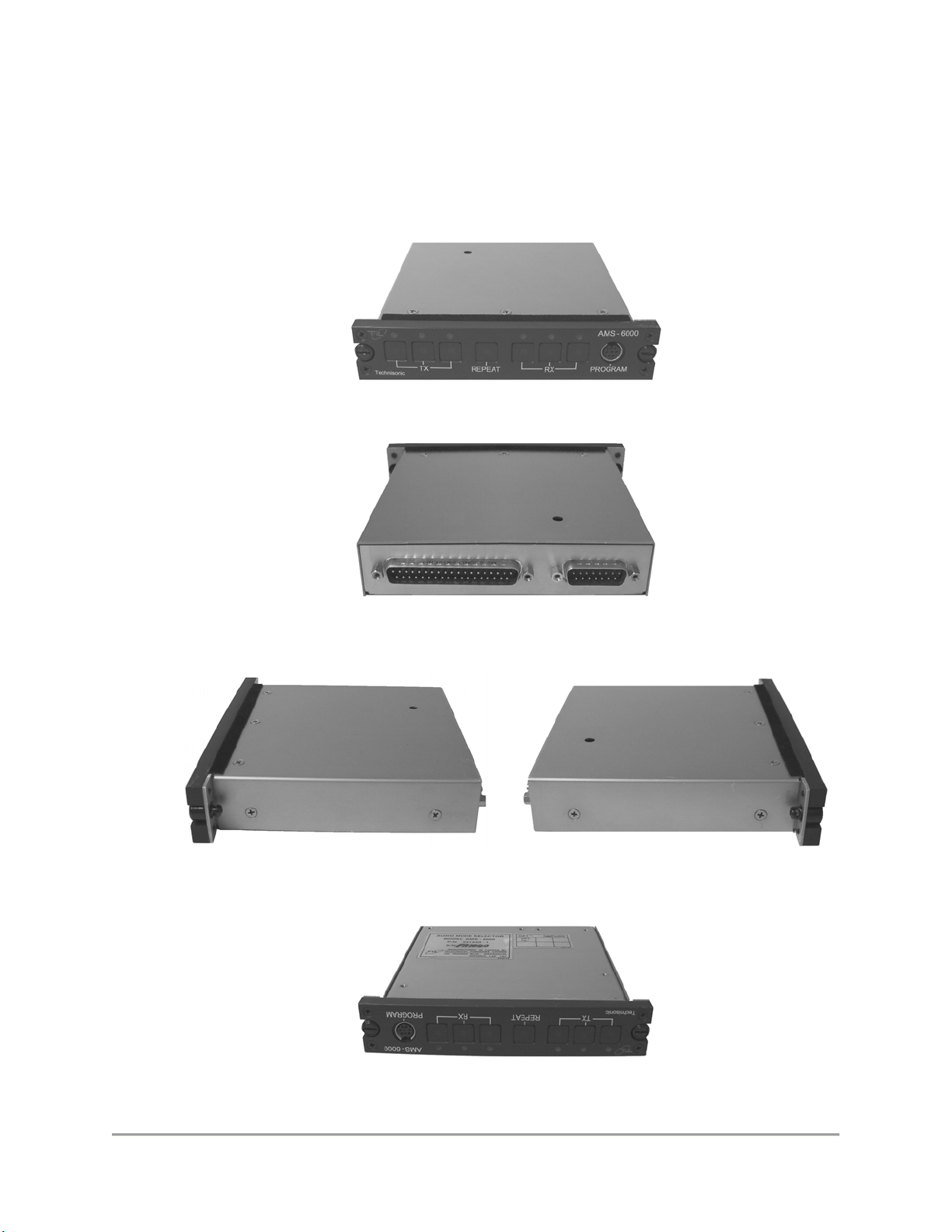
The complete unit is shown in Figures 2.2.1A, 2.2.1B, 2.2.1C and 2.2.1D.
FIGURE 2.2.1A AMS-6000 Front View
FIGURE 2.2.1B AMS-6000 Back View
FIGURE 2.2.1C AMS-6000 Side Views
FIGURE 2.2.1D AMS-6000 Bottom View

TECHNISONIC INDUSTRIES LIMITED
www.til.ca
AMS-6000 Maintenance Manual TiL 10RE427
2-3
MODULE REPLACEMENT PROCEDURE – continued
2.2.2 Removing the AMS-6000 Chassis Cover
Remove the seven 7 4-40 x 3/16” Flat Phil screws holding the chassis cover (top) labeled
as A1 through A7. See Figures 2.2.2A. Gently remove chassis cover. See Figures 2.2.2B.
Right side from Front
Left side from Front
FIGURE 2.2.2A Removing the Top Chassis Cover Screws
FIGURE 2.2.2B Chassis Cover (Top) Removed
A1
A2
A3
A5
A6
A7
A4
Strip of Felt Tape
PN 038632
Other manuals for AMS-6000
1
Table of contents


