HBM MP60DP User manual

A0623-6.1 en/de/fr
Profibus-Interface
MP60DP
Operating manual
Bedienungsanleitung
Manuel d’emploi

English Page 3 −20. . . . . . . . . . . . . . . . . . . . . . . . . . . . . . . . . . . . . . . . . . . . . . . . .
Deutsch Seite 21 −38. . . . . . . . . . . . . . . . . . . . . . . . . . . . . . . . . . . . . . . . . . . . . . .
Français Page 39 −55. . . . . . . . . . . . . . . . . . . . . . . . . . . . . . . . . . . . . . . . . . . . . . .

3
PME−MP60DP
HBMA0623−6.1 en/de/fr
Contents Page
1 Introduction 4. . . . . . . . . . . . . . . . . . . . . . . . . . . . . . . . . . . . . . . . . . . . . . . . .
2 How to connect to a PLC 5. . . . . . . . . . . . . . . . . . . . . . . . . . . . . . . . . . . . .
2.1 Configuring and assigning parameters 6. . . . . . . . . . . . . . . . . . . . . . .
3 Installation 8. . . . . . . . . . . . . . . . . . . . . . . . . . . . . . . . . . . . . . . . . . . . . . . . . .
4 Connections 9. . . . . . . . . . . . . . . . . . . . . . . . . . . . . . . . . . . . . . . . . . . . . . . . .
4.1 Pin assignment 9. . . . . . . . . . . . . . . . . . . . . . . . . . . . . . . . . . . . . . . . . . .
5 Operation via the keyboard 10. . . . . . . . . . . . . . . . . . . . . . . . . . . . . . . . . . .
5.1 Expanded menus 11. . . . . . . . . . . . . . . . . . . . . . . . . . . . . . . . . . . . . . . . .
6 Setup for Profibus 12. . . . . . . . . . . . . . . . . . . . . . . . . . . . . . . . . . . . . . . . . . .
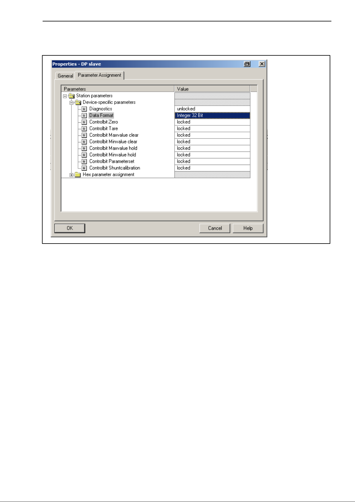
6.1 Parameter assignment 12. . . . . . . . . . . . . . . . . . . . . . . . . . . . . . . . . . . . .
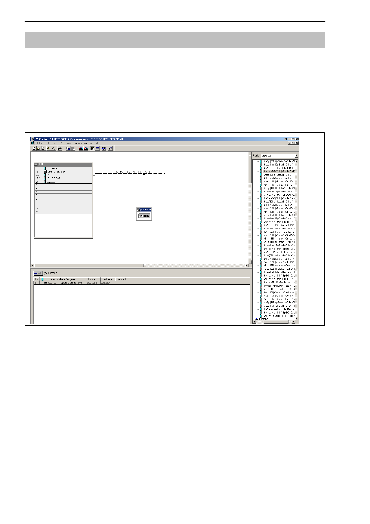
6.2 Configuration 14. . . . . . . . . . . . . . . . . . . . . . . . . . . . . . . . . . . . . . . . . . . . .
6.2.1 Defining your own configuration combinations 15. . . . . . . . . . .
6.3 Cyclical data exchange 16. . . . . . . . . . . . . . . . . . . . . . . . . . . . . . . . . . . .
6.3.1 Inputs (from MP55IBS to the PLC) 16. . . . . . . . . . . . . . . . . . . . .
6.3.2 Outputs (from the PLC to MP55IBS) 18. . . . . . . . . . . . . . . . . . .
6.4 Diagnosis 19. . . . . . . . . . . . . . . . . . . . . . . . . . . . . . . . . . . . . . . . . . . . . . . .

4PME−MP60DP
HBM A0623-6.1 en/de/fr
1 Introduction
This Operating Manual describes only those functions which differ from the
MP60. The features of the MP60DP correspond to those of the MP60.
The MP60DP carrier−frequency measurement module has been expanded to
include a Profibus interface. The features on the CAN−interface remain the
same; the object directory is expanded to include some parameters for the
Profibus connection.
The Profibus connection is made using a 9−pin sub−D connector (conforming
to standard) on the front panel next to the transducer port.
DP protocol is used on the Profibus.
The following are communicated:
−the measured values (gross, net, peak values)
−the status of the limit switches
−control bits for taring, zeroing, peak value store control and changing the
parameter set, and
−optionally, the limit values

5
PME−MP60DP
HBMA0623-6.1 en/de/fr
2 How to connect to a PLC
The steps in successfully connecting to the Profibus:
1. Physically connect the device to the Profibus (see page 8 and page 9)
2. Configure the device parameters, see page 12 (can also be carried out
using HBM‘s “PME-Assitent“ software).
3. Configure the Profibus message and set up its parameters with the aid of a
configuration tool (such as Step7) and GSE files, or manually as shown in
chapter 6.2.
A GSE file describes the properties of a Profibus node in standardized form.
The configuration tool uses it to define which data held on individual bus
nodes will be exchanged on the Profibus.
A default GSE file for PME modules is supplied with the device (on system
CD: hbmxxx.gsd = German version; hbmxxxgse = English version).
PROFIBUS−DP
System configuration
Profibus
configurator
PLC GSE
Electronic device data sheets (GSE files)
Fig. 2.1: Configuration with the aid of GSE files

6PME−MP60DP
HBM A0623-6.1 en/de/fr
2.1 Configuring and assigning parameters
•Start your configuration program (e.g. Step7; if you have no configuration
program, proceed to chapter 6.2)
•Load the HBM GSD file (PME system CD incl. GSD/GSE files for PME)
•Add an HBM device (Hardware catalog)
•From the hardware catalog choose the configuration you want on the
Profibus.
Fig. 2.2: Hardware configuration

7
PME−MP60DP
HBMA0623-6.1 en/de/fr
•Double-click on the configured entries to open the properties window and
select the required parameters.
Fig. 2.3: Setting parameters
Notes for users of the Simatic S7 PLC:
•To download consistent data of 3 bytes or over 4 bytes, use special
function modules SFC14 to read and SFC15 to write.
•In the case of the S7 3xx a maximum of 32 bytes of consistent data can be
downloaded.
To find out the meaning of the status bits and control word bits please refer to
the tables in chapter 6.3.

8PME−MP60DP
HBM A0623-6.1 en/de/fr
3 Installation
•Connect the MP60DP module to a 24 V supply voltage.
•Connect the Profibus cable to the MP60DP module. Ensure that a
terminating resistance is connected to the first and last Profibus unit (the
housing of the Profibus connector usually contains a sliding switch for this
purpose).
Example:
PLC
First device in
the bus line
Last device in
the bus line
sliding switch of Profibus
connector to ”Resistance ON”
sliding switch of Profibus connector to
”Resistance ON” .
Profibus
connector
Profibus
connector
Fig. 3.1: Profibus operation

9
PME−MP60DP
HBMA0623-6.1 en/de/fr
4 Connections
Warning
Please note the safety instructions before commissioning the device.
4.1 Pin assignment
For the pin assignment of the MP60DP module please refer to the Operating
Manual “PME industrial measurement electronics with MP60/MP07 module
field bus link”. On the front panel of the MP60DP is an additional 9−pin D-sub
connection socket for the Profibus connection.
Profibus
connection
socket
1
5
6
9GND
RS485-RTS
RS485-B
RS485-A
Vcc (5V)
6
0
Fig. 4.1: Profibus connection in accordance with standard

10 PME−MP60DP
HBM A0623-6.1 en/de/fr
5 Operation via the keyboard
During measurement you can press +−−to view the status messages in
the display (e.g. mV; V; Out,In; error messages).
Next to the status message “ERROR” the display shows the status of the
Profibus DP connection. One of the following status messages is displayed in
each case:
BD_SEAR (baud rate search)
WT_PARM (waiting for parameter)
WT_CONF (waiting for configuration)
DATA_EX (cyclical data communication)
ERROR (bus error)
The LED shows the operating status (ready to take measurements, overflow
etc.) of the MP60DP. Instead of the CAN status (as with the MP60), however,
the Profibus status is displayed.
Operating status:
LED
colour Status Meaning
Profibus status
Green Steady light DATA_EX status
Yellow Steady light BD_SEAR, WT_PARM, WT_CONF status
Red Steady light ERROR status
The representation of the other operating statuses is the same as that of the
MP60.

11
PME−MP60DP
HBMA0623-6.1 en/de/fr
5.1 Expanded menus
New “Profibus” group in set-up mode:
Groups
SET +−
DIALOGUE ... PEAK STORE IN/OUT CAN-BUS PROFIBUS ADDITION
FUNCTION
Password Operatn. Output1 Baud rate Address AmplType
PassStat InputMin ModeOut1 Address MAINGRP PrgVers
Language InputMax Output2 Profile >0<Rf kNm1)
I.DataS ClearPkV ModeOut2 Output HW synchr
I.Displ. kN/s1) Output3 OutR. ms Keyboard
I.Transd MAINGRP ModeOut3 PDO-Frmt SNo
I.Meas Output4 MAINGRP HW vers.
I.Condit ModeOut4 MAINGRP
I.Analog Zeroing
I.LimVal Tare
I.PStore PkMomMax
I.I/O PkHldMax
I.CAN PkMomMin
I.AddFnc PkHldMin
MAINGRP ParaCo1
ParaCo2
InpFunc
MAINGRP
CAN-bus ADDITIONFUNCTION
+
−
SET SET
In/Out
SET 3 −123
↓
↑+/−
Groups
PROFIBUS
SET
Address
Fig. 5.1: Setting up the Profibus address
Overview of parameters
Up
+
Down
−
SET

12 PME−MP60DP
HBM A0623-6.1 en/de/fr
6 Setup for Profibus
6.1 Parameter assignment
The amplifier parameters are set via the keyboard or CAN−interface, as on
the MP60. The Profibus DP parameter assignment telegram defines some
parameters for the DP communication. If you use Profibus parameter
assignment tools which are able to evaluate the GSD files of GSD revision 1,
the following parameters are available for selection:
Parameter name Available
values Default Meaning
Diagnosis disabled
released released release of external diagnosis
Data format integer 16 bits
integer 32 bits
floating point
integer 16 bits defines the coding format for
measured values
Zeroing control bit disabled
released disabled releases function for control of
output control word
Taring control bit disabled
released disabled releases function for control of
output control word
Clear maximum
control bit disabled
released disabled releases function for control of
output control word
Clear minimum
control bit disabled
released disabled releases function for control of
output control word
Hold maximum
control bit disabled
released disabled releases function for control of
output control word
Hold minimum
control bit disabled
released disabled releases function for control of
output control word
Parameter set
control bit disabled
released disabled releases function for control of
output control word
Tab 6.1: Meaning of the parameters
The data format set applies to all the measured values exchanged in the
cyclical data communication. The definition of the decimal places for the
formats integer 16 bits and integer 32 bits is adopted from the module setting
(display, CAN−bus) (e.g. when 3 decimal places is specified, 2.0 mm is
communicated as integer value 2000). The choice of data format also affects
the length of the input data (integer 16 bits = 1 word per analogue value,
integer 32 bits and floating = 2 words per analogue value).

13
PME−MP60DP
HBMA0623-6.1 en/de/fr
The targeted operation of the required control bits in the control word allows
you to secure all the functions not required against accidental operation in the
event of an error; otherwise, for example, the zero point set could be lost.
If you are using older parameter assignment tools the parameter values will
have to be converted to decimal or hexadecimal values:
Octet Bits Parameter name Available values Default Meaning
0 0..7 reserved 0 0 do not change1)
1−2 all Diagnosis 0 = disabled
0xffff = released released release of external
diagnosis
3 all Data format 0 = integer 16 bits
1 = integer 32 bits
2 = floating point
integer 16 bits defines the coding
format for measured
values
5 0 Zeroing control
bit 0 = disabled
1 = released disabled releases function for
control of output
control word
5 1 Taring control bit 0 = disabled
1 = released disabled releases function for
control of output
control word
5 4 Control bit
Delete maximum 0 = disabled
1 = released disabled releases function for
control of output
control word
5 5 Control bit
Delete minimum 0 = disabled
1 = released disabled releases function for
control of output
control word
5 6 Control bit
Hold maximum 0 = disabled
1 = released disabled releases function for
control of output
control word
5 7 Control bit
Hold minimum 0 = disabled
1 = released disabled releases function for
control of output
control word
4 0−1Parameter set
control bits 0 = disabled
3 = released disabled releases function for
control of output
control word
Tab 6.2: Contents of the parameter assignment message
1) changed by your parameter assignment tool in certain circumstances

14 PME−MP60DP
HBM A0623-6.1 en/de/fr
6.2 Configuration
The configuration defines which data content is exchanged in the cyclical data
communication. The following data is available for selection:
Input values:
Name Meaning Length
Gross gross measured value 1 or 2
words
Net net measured value (gross minus tare value) 1 or 2
words
Max contents of the maximum store 1 or 2
words
Min contents of the minimum store 1 or 2
words
Pk−Pk peak−to−peak, difference between max and min 1 or 2
words
Status1 status word with status of the limit switches and gen. error
bits 1 word
Status2 double status word with differentiated error flagging 2 words
Output values:
Name Meaning Length
Control word control word for triggering taring, zeroing, clearing the peak
value store, parameter set selection, etc. 1 word
Limit1 level at which limit switch 1 responds 1 or 2
words
Limit2 level at which limit switch 2 responds 1 or 2
words
Limit3 level at which limit switch 3 responds 1 or 2
words
Limit4 level at which limit switch 4 responds 1 or 2
words
The formats of the cyclically communicated data content are specified in detail
in chapter 6.3. The measured values are offered optionally as a 16-bit integer,
32-bit integer or 32 bit float. The values are always scaled to physical size
with the number of decimal places of your choice. Information on whether the
16 bit format or a 32 bit format is used and on the number of decimal places is
defined in the parameter assignment message.
Typical combinations are predefined in the GSD file. If you require other
combinations you can expand the GSD file accordingly using the following
specifications.

15
PME−MP60DP
HBMA0623-6.1 en/de/fr
6.2.1 Defining your own configuration combinations
Only one configuration entry is available. The special identification format
(special format) must be used for this. The manufacturer−specific data
specifies the contents and thus also the length of the input data and is 2 bytes
in length.
CFG entry no. Meaning Contents
0channel 1 special format with inputs and outputs, maximum 9 words
output, maximum 13 words input, 2 bytes comment length
(data)
The following input and output data can be configured for the cyclical data
communication. The choice of which data is actually transferred is
communicated via the manufacturer−specific data of the special identification
format.
Configuration
manufacturer−
specific data
Length of cyclical data
inputs Length of cyclical data
outputs Contents of cyclical
data
Byte no. Bit no. (words) (words)
Input values:
0 0 1(2) Gross
0 1 1(2) Net
0 2 1(2) Max
0 3 1(2) Min
0 4 1(2) Peak−to−peak
0 5 1 Status1
0 6 2 Status2
Output values:
1 0 1 Control word
1 1 1(2) Limit value level 1
1 2 1(2) Limit value level 2
1 3 1(2) Limit value level 3
1 4 1(2) Limit value level 4
Tab 6.3: Selecting the data content via the manufacturer−specific data
The length of the input data is the sum of all the data lengths selected for the
communication in words. When selecting the 32 bit format and the float format
for measured values, the length values in brackets must be used.

16 PME−MP60DP
HBM A0623-6.1 en/de/fr
The configuration telegram thus has the following format:
CFG byte Meaning Permitted values for CFG (hex.)
1 header 0xC2 (inputs and outputs, 2 bytes manufacturer−specific
data)
2length of outputs 0x40 −0x48 (1 to 9 words of outputs) or
0xC0 −0xC8 (1 to 9 words of outputs with consistency)
3length of inputs 0xC0 −0xCC or
0x40 −0x7C (1 to 13 words of inputs with/without
consistency)
4user−specific data Input data selection of the data content (see
Tb )
5
p
Output data
(
Tab 6.3)
Tab 6.4: Contents of the configuration telegram
When using the 32 bit formats data consistency must always be set.
6.3 Cyclical data exchange
Depending on the configuration, the following data content is exchanged:
6.3.1 Inputs (from MP55IBS to the PLC)
Measured values
Measured values can be communicated in various forms of representation.
The forms of representation available for selection are floating (2 words, 32
bit), 16 bit fixed point number (1 word, 16 bit integer in two’s complement,
decimal place must be known to the reader) or 32 bit fixed point number (2
words, 32 bit integer in two’s complement, decimal place must be known to
the reader). For conversion of the values to fixed point representation the
number of decimal places in the module parameter assignment (display,
CAN−bus) is used as a basis.

17
PME−MP60DP
HBMA0623-6.1 en/de/fr
Status 1
Bits Name Meaning
0 Ovfl measured values overflow
1 AOutOvfl analogue output overflow
2 ScalErr scaling defective
3 EEPROMErr EEPROM (parameter set) defective
4 Limit1 status of limit switch 1
5 Limit2 status of limit switch 2
6 Limit3 status of limit switch 3
7 Limit4 status of limit switch 4
8 PAR1 active parameter set bit 1
9 PAR2 active parameter set bit 1
10..14 res reserved
15 MViO Measured value in order 1) (if bit 0,2,3=0)
Tab 6.5: Contents of status 1
1) Meaning of MViO:
NOR operation of: MesswOvfl, SkalErr, EEPROMErr.
MesswOvfl is the OR operation of ADCOvfl, HardwOvfl, GrossOvfl, NetOvfl
The parameter set number is coded in 2 bit binary:
Bit 8 Bit 9 Parameter set no.
0 0 1
1 0 2
0 1 3
1 1 4
Status 2
Double status word 2 returns detailed error flagging.
Bits Name Meaning
0 HardwOvfl hardware overflow
1 ADCOvfl ADC overflow
2 GrossOvfl gross signal overflow
3 NetOvfl net signal overflow
4 AOutOvfl analogue output overflow
5 MaxOvfl maximum overflow
6 MinOvfl minimum overflow
7 NegOvfl overflow in negative direction
8 Limit1 status of limit switch 1
9 Limit2 status of limit switch 2
10 Limit3 status of limit switch 3
11 Limit4 status of limit switch 4
12 ScalInError scaling input invalid
13 ScalOutError scaling output invalid
14 GainError nominal value exceeded
15 InitError works calibration defective
16 TransducerError transducer error
17..31 res reserved
Tab 6.6: Contents of status 2

18 PME−MP60DP
HBM A0623-6.1 en/de/fr
6.3.2 Outputs (from the PLC to MP55IBS)
Limit values
Limit values are displayed in the same format as the measured values (16 bit
integer, 32 bit integer or floating format). The operating direction and
hysteresis remain unchanged and are set via the operating panel or the
CAN−bus.
Control word
Bits Name Meaning
0 ZERO 0−1 autom. triggers zeroing
1TAR 0−1 triggers taring
2 SHUNT SHUNT ON / OFF
3 res reserved
4 CLRMAX 0−1 clears the MAX peak value store
5 CLRMIN 0−1 clears the MIN peak value store
6 HOLDMAX 1: freeze MAX peak value store
7 HOLDMIN 1: freeze MIN peak value store
8 PAR1 parameter set selection bit 1
9 PAR2 parameter set selection bit 2
10..15 res reserved
Tab 6.7: Contents of control word

19
PME−MP60DP
HBMA0623-6.1 en/de/fr
6.4 Diagnosis
The MP60DP module makes a device diagnosis available as an external
diagnosis which can be released via the parameter assignment diagram.
The external diagnosis is 4 bytes long. The first byte contains the identification
character for the version number. The second byte contains the identification
character for device diagnosis. In the third and fourth bytes one bit each is
reserved for various fault causes.
Octet Bits Value Meaning
0 0..7 c1 version 1
1 0..7 4 length of device diagnosis is 4 bytes in total
2 0 0
1hardware overflow
2 1 ADC overflow
2 2 0
1gross overflow
2 3 0
1net overflow
2 4 0
1analogue output overflow
2 5 0
1maximum overflow
2 6 0
1minimum overflow
2 7 res
3 0..3 res
3 4 0
1scaling of input characteristics defective
3 5 0
1scaling of output characteristics defective
3 6 0
1nominal value exceeded
3 7 0
1works calibration defective
4 0 0
1transducer error
4 1...7 res
Tab 6.8: Contents of diagnosis

20 PME−MP60DP
HBM A0623-6.1 en/de/fr
Table of contents
Languages:
Other HBM Recording Equipment manuals
Popular Recording Equipment manuals by other brands

Extron electronics
Extron electronics Computer-Video Interface RGB 558 AKM Specifications

Focusrite
Focusrite Clarett 2Pre user manual

Airfield Audio
Airfield Audio LIMINATOR owner's manual

Essence
Essence HDACC Operation manual

Digital ID View
Digital ID View 16-CH user manual

National Instruments
National Instruments UMI-7774 USER GUIDE AND SPECIFICATIONS