manuals.online logo
Brands
  1. Home
  2. •
  3. Brands
  4. •
  5. Viessmann
  6. •
  7. Recording Equipment
  8. •
  9. Viessmann 5577 User manual

Viessmann 5577 User manual

Bedienungsanleitung
Operation Manual
Innovation,
diebewegt!
5577
Soundmodul
Straßengitarrist
Sound module
Street Guitarist
1. Wichtige Hinweise / Important information ........................................................ 2
2. Einleitung / Introduction..................................................................................... 2
3. Einbau / Mounting ............................................................................................. 2
4. Anschluss / Connection..................................................................................... 3
5. Fehlersuche und Abhilfe / Trouble-shooting ...................................................... 4
6. Technische Daten / Technical data.................................................................... 6
AC
~
DC
=
2
DE EN
1. Wichtige Hinweise
Bitte lesen Sie vor der ersten Anwendung des Produktes
bzw. dessen Einbau diese Bedienungsanleitung auf-
merksam durch. Bewahren Sie diese auf, sie ist Teil des
Produktes.
1.1 Sicherheitshinweise
Vorsicht:
Verletzungsgefahr!
Für die Montage sind Werkzeuge nötig.
Stromschlaggefahr!
Die Anschlussdrähte niemals in eine Steckdose einfüh-
ren! Verwendetes Versorgungsgerät (Transformator,
Netzteil) regelmäßig auf Schäden überprüfen. Bei Schä-
den am Versorgungsgerät dieses keinesfalls benutzen!
Alle Anschluss- und Montagearbeiten nur bei abgeschal
-
teter Betriebsspannung durchführen!
Ausschließlich nach VDE/EN gefertigte Modellbahn-
transformatoren verwenden!
Stromquellen unbedingt so absichern, dass es bei einem
Kurzschluss nicht zum Kabelbrand kommen kann.
1.2 Das Produkt richtig verwenden
Dieses Produkt ist bestimmt:
- Zum Einbau in Modelleisenbahnanlagen und Dioramen.
- Zum Anschluss an einen Modellbahntransformator
(z. B. Art. 5200) bzw. an eine Modellbahnsteuerung mit
zugelassener Betriebsspannung.
- Zum Betrieb in trockenen Räumen.
Jeder darüber hinausgehende Gebrauch gilt als nicht be-
stimmungsgemäß. Für daraus resultierende Schäden haftet
der Hersteller nicht.
1.3 Packungsinhalt überprüfen
Kontrollieren Sie den Lieferumfang auf Vollständigkeit:
- Soundmodul mit blauer Leitung
- Montagematerial (2 Schrauben, 8 Stecker)
- Anleitung
2. Einleitung
Modellbahn mit allen Sinnen erleben: Das stationäre
Soundmodul ergänzt die Szenen der Bewegten Welten
um die passenden Geräusche. Das Soundmodul verfügt
über einen internen Lautsprecher und einen Anschluss für
einen externen Lautsprecher.
3. Einbau
Die Befestigung des Bausteins erfolgt mit den beiliegenden
Schrauben. Für optimalen Klang beachten Sie folgende
Hinweise:
1. Der Lautsprecher ist im Modul integriert. Für eine gute
Schallverteilung darf die Oberseite des Moduls nicht
verdeckt sein.
1. Important information
Please read this manual completely and attentively before
using the product for the rst time. Keep this manual. It is
part of the product.
1.1 Safety instructions
Caution:
Risk of injury!
Tools are required for installation.
Electrical hazard!
Never put the connecting wires into a power socket!
Regularly examine the transformer for damage. In case
of any damage, do not use the transformer.
Make sure that the power supply is switched off when
you mount the device and connect the cables!
Only use VDE/EN tested special model train transform-
ers for the power supply!
The power sources must be protected to avoid the risk
of burning cables.
1.2 Using the product for its correct purpose
This product is intended:
- For installation in model train layouts and dioramas.
- For connection to an authorized model train transformer
(e. g. item 5200) or a digital command station.
- For operation in dry rooms only.
Using the product for any other purpose is not approved
and is considered inappropriate. The manufacturer is not
responsible for any damage resulting from the improper
use of this product.
1.3 Checking the package contents
Check the contents of the package for completeness:
- Sound module with blue cable
- Mounting material (2 screws, 8 plugs)
- Manual
2. Introduction
Experience the model railway with all your senses: The
stationary sound module provides the specic sounds
to the scenes in the animated world. Sound module is
equipped with integral loudspeaker and connection for an
external loudspeaker.
3. Mounting
Fix the module with the enclosed screws. To ensure an
optimal sound reproduction of the module, please note the
following hints:
1. The loudspeaker is an integral part of the module. The
upper surface of the module must always be uncovered
in order to provide a good sound dispersion.
3
2. Soundmodul möglichst in Richtung der Zuschauer/Zuhörer
ausrichten, also keine Über-Kopf-Montage unter der Anlage.
3. Das Soundmodul sollte sich dort befinden, wo das
entsprechende Funktionsmodell auf Ihrer Anlage vor-
kommt. Sie können das Modul auch auf der Anlage
(z. B. in einem Gebäude etc.) einbauen. So erreichen
Sie noch besseren Klang und eine bessere Überein-
stimmung von sichtbarer und hörbarer Geräuschquelle.
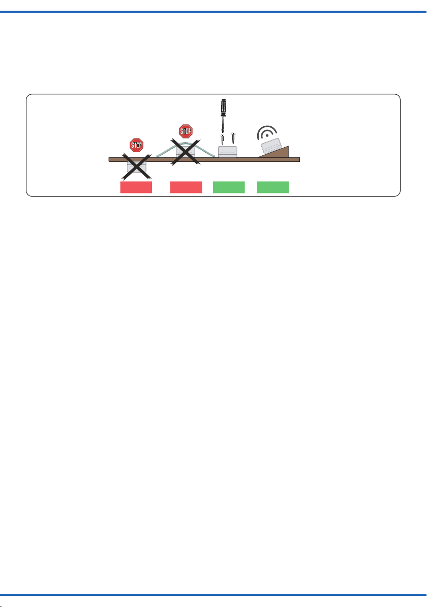
Einbaulage für Soundmodule
Mounting of sound modules
Lautsprecherschlitze nicht abdecken!
Mit Lautsprecher nach oben montieren!
Do not cover loudspeaker slots!
Mount the module with loudspeaker on top!
Falsch RichtigFalsch
wrong correctwrong
Optimal
ideal
Fig. 1
Abb. 1
4. Anschluss
Geeignete Kabel: Der geringe Strombedarf des Soundmo-
duls erlaubt es, entsprechend dünn dimensionierte Kabel,
die sich gut versteckt verlegen lassen, zu verwenden. Wir
empfehlen Litze mit einem Querschnitt von 0,14 mm² (z. B.
Viessmann Art. 6860 – 6869 oder 68603 – 68693).
Zum automatischen Betrieb (Diorama-Modus) des Sound-
moduls beachten Sie bitte Abb. 2 (B). Zum manuellen
Betrieb des Soundmoduls beachten Sie bitte Abb. 2 (A).
Ein Betrieb des Soundmoduls ist auch ohne die eMotion
Figur „Straßengitarrist“, Art. 1510 möglich.
4.1 Anschluss mit einem Taster
Zum Betrieb des Soundmoduls mit Taster beachten Sie
bitte Abb. 2 (A).
- Nach dem ersten Tastendruck wird der erste Gitarren-
song abgespielt (optional mit Synchronbewegung des
Straßengitarristen, Art. 1510).
- Nach dem zweiten Tastendruck wird der zweite Gitarren-
song abgespielt (optional mit Synchronbewegung).
- Nach dem dritten Tastendruck wird wieder der erste
Gitarrensong abgespielt (optional mit Synchronbewe-
gung).
- Usw.
4.2 Anschluss mit einem Umschalter
Zum Betrieb des Soundmoduls mit Umschalter beachten
Sie bitte Abb. 2 (B).
- Die Reihenfolge ist gleich wie bei der Verwendung
eines Tasters, aber die Songs werden alle zwei bis drei
Minuten automatisch abgespielt.
4.3 Anschluss eines externen Lautsprechers
Das Soundmodul verfügt über einen Ausgang für einen ex-
ternen Lautsprecher mit den elektrischen Werten min. 8 Ohm
Impedanz und min. 1 Watt Leistung (erhältlich im Elektronik-
Fachhandel). Bei Anschluss eines externen Lautsprechers
wird der eingebaute Lautsprecher ausgeschaltet.
1. Ziehen Sie das kurze blaue, am Soundmodul befindliche
Kabel aus der Buchse rechts daneben.
2. If possible, gear the sound module towards the spectator,
so please avoid upside down mounting under the layout.
3. The sound module should be installed near the respec-
tive functional model on your layout. You can also install
the module on the layout, e. g. in a building. This way
you can even have a better sound and an optimal con-
cordance between the visible and the audible sound
source.
4. Connection
Fitting cables: Due to the low current consumption thin
cables can be used which can easily be hidden. It is rec-
ommended to use a cross section of 0.14 mm² (e. g.
Viessmann items 6860 – 6869 or 68603 – 68693).
For automatic operation (diorama mode) of the sound
module, please refer to g. 2 (B). For manual operation of
the sound module, please refer to g. 2 (A).
It is also possible to operate the sound module without the
eMotion gure “Street Guitarist”, item 1510.
4.1 Connection with a push-button
To operate the sound module with a push-button, please
refer to g. 2 (A).
- After pushing the button once, the first guitar song is
played (optionally with synchronous movement of the
street guitarist, item 1510).
- After pushing the button a second time, the second guitar
song is played (optionally with synchronous movement).
- After pushing the button a third time, the first guitar song
is played again (optionally with synchronous movement).
- Etc.
4.2 Connection with an on-off switch
To operate the sound module with an on-o switch, please
refer to g. 2 (B).
- The sequence is the same as when using a push-button,
but the songs are played automatically every two to
three minutes.
4.3 Connection of an external loudspeaker
The sound module is equipped with an output for an exter-
nal loudspeaker with electrical values of 8 ohm impedance
at least and min. 1 watt power (can be purchased in a spe-
cialized shop for electronics). In case you connect an exter-
nal loudspeaker the integral loudspeaker will be switched o.
1. Please pull the sound module’s short blue cable out of
the next socket to the right.
4
Sekundär
0-10-16 V~
16 V
Primär
230 V~
Gefertigt nach
VDE 0570
EN 61558
Lichttransformator
5200
Nur für trockene Räume
Primär 230 V 50 - 60 Hz
Sekundär max. 3,25 A52 VA
ta 25°CIP 40
10 V
0 V
viessmann 5550
Universal Ein-Aus-Umschalter
gelb
braun
z. B. / e. g. 5200
grün
z. B. / e. g. 5550
Gleichspannungsbetrieb:
Synchroneingang mit Pol der
Spannungsquelle verbinden.
Synchroneingang mit Pol der
Spannungsquelle verbinden.
5577
Universal Tasten - Stellpult
5547
Viessmann
braun
1510 optional
/ brown
/ yellow
/ green
DC operation:
Connect “Synchroneingang” to
pole of the power supply.
Connect “Synchroneingang” to
pole of the power supply.
brown
Gleichspannungsbetrieb:
Braunes Kabel: mit + Pol der Spannungsquelle verbinden.
Gelbes Kabel: mit - Pol der Spannungsquelle verbinden.
DC operation:
Brown cable: connect to the + pole of the power supply.
Yellow cable: connect to the - pole of the power supply.
Fig. 2
Abb. 2
A
B
Sekundär
0-10-16 V~
16 V
Primär
230 V~
Gefertigt nach
VDE 0570
EN 61558
Lichttransformator
5200
Nur für trockene Räume
Primär 230 V 50 - 60 Hz
Sekundär max. 3,25 A52 VA
ta 25°CIP 40
10 V
0 V
viessmann 5550
Universal Ein-Aus-Umschalter
orange
isolieren
Lautsprecher
(min. 8 Ω)
/ orange
/ insulate
Loudspeaker
(min. 8 Ω)
Fig. 3
Abb. 3
Kleinen Schraubendreher benutzen!
Use a small screwdriver!
Fig. 4
Abb. 4
5
2. Isolieren Sie das blaue Kabel, so dass es keinen Kon-
takt mit anderen Kabeln haben kann.
3. Montieren Sie den externen Lautsprecher am vorgese-
henen Einbauort.
4. Verlegen Sie die beiden Anschlussleitungen des exter-
nen Lautsprechers zum Soundmodul.
5. Verbinden Sie die Anschlussleitungen mit den beiden
Buchsen gemäß Abb. 3.
4.4 Lautstärke einstellen
Sie können die Wiedergabelautstärke des Soundmoduls ein-
stellen. Diese Einstellung gilt sowohl für den eingebauten als
auch für einen alternativ vorhandenen externen Lautsprecher.
Zum Einstellen der Lautstärke verwenden Sie bitte einen
geeigneten Schraubendreher (Schlitz), wie in Abb. 4 gezeigt:
- Lauter:
Drehen Sie das Potentiometer nach rechts.
- Leiser:
Drehen Sie das Potentiometer nach links.
5. Fehlersuche und Abhilfe
Jedes Viessmann-Produkt wird unter hohen Qualitätsstan-
dards gefertigt und vor seiner Auslieferung geprüft. Sollte
es dennoch zu einer Störung kommen, können Sie anhand
der folgenden Punkte eine erste Überprüfung vornehmen.
Überprüfen Sie bitte als erstes die Stromzuführungen
und die Verkabelung.
Soundmodul spielt keinen Sound ab. Am externen
Lautsprecher ist kein Sound zu hören.
- Soundmodul muss nach Abb. 2 angeschlossen sein.
Wenn der Synchroneingang nicht wie in den Abbildun-
gen belegt ist, kann kein Sound abgespielt werden!
- Poti nach rechts drehen.
- Stellen Sie sicher, dass der kleine blaue Stecker am un-
teren Gehäuserand des Soundmoduls aus der Buchse
daneben entfernt und isoliert ist.
Schließen Sie den externen Lautsprecher gemäß
Abb. 3 an.
Wenn Sie die Fehlerursache nicht finden und beheben
können, nehmen Sie bitte Kontakt mit uns auf (service@
viessmann-modell.com). Senden Sie uns den Artikel zur
Kontrolle bzw. Reparatur bitte erst nach Rücksprache zu.
2. Insulate the blue cable to avoid any contact with other
cables.
3. Mount the external loudspeaker to the intended place.
4. Lay the two wires of the external loudspeaker to the
sound module.
5. Connect the two wires to the two sockets according to
fig. 3.
4.4 Volume adjustment
The sound module is equipped with a volume control for
the sound. The adjustment is valid both for the integral
loudspeaker and for an external loudspeaker.
To adjust the volume, use a slotted screwdriver and pro-
ceed as follows (see g. 4):
- Increase volume:
Turn the poti to the right.
- Reduce volume:
Turn the poti to the left.
5. Trouble-shooting
All Viessmann products are produced with high quality
standards and are checked before delivery. Should a fault
occur nonwithstanding, you can do a rst check.
Please check rst the power supply and the wiring.
No sound from the module. No sound from the exter-
nal loudspeaker.
- Sound module has to be connected acc. to fig. 2. If the
synchronous input is not connected as shown in the
figures, playing of the sound will not be possible!
- Turn the poti to the right.
- Please make sure that the small blue plug at the housing
of the sound module is removed from the socket and is
insulated.
Connect the external loudspeaker as shown in fig. 3.
If you are unable to nd and x the cause for the problem
please contact our service department (service@viess-
mann-modell.com). Please send the item to the Viess-
mann service department for check and repair only after
consultation.
6
Änderungen vorbehalten. Keine Haftung für Druckfehler
und Irrtümer.
Die aktuelle Version der Anleitung finden Sie auf der Viess-
mann Homepage unter der Artikelnummer.
Subject to change without prior notice. No liability for
mistakes and printing errors.
You will nd the latest version of the manual on the Viess-
mann website using the item number.
Entsorgen Sie dieses Produkt nicht über den
(unsortierten) Hausmüll, sondern führen Sie
es der Wiederverwertung zu.
Do not dispose of this product through (unsorted)
domestic waste, supply it to recycling instead.
Modellbauartikel, kein Spielzeug! Nicht geeignet für
Kinder unter 14 Jahren! Anleitung aufbewahren!
Model building item, not a toy! Not suitable for children
under the age of 14 years! Keep these instructions!
Ce n’est pas un jouet! Ne convient pas aux enfants de moi-
ns de 14 ans! Conservez cette notice d’instructions!
Não é um brinquedo! Não aconselhável para menores de
14 anos! Conservar o manual de instruções!
Modelbouwartikel, geen speelgoed! Niet geschikt voor
kinderen onder 14 jaar! Gebruiksaanwijzing bewaren!
Articolo di modellismo, non è un giocattolo! Non adatto
a bambini al di sotto dei 14 anni! Conservare istruzioni per
l’uso!
Artículo para modelismo ¡No es un juguete! No
recomendado para menores de 14 años! Conserva las
instrucciones de servicio!
DE
EN
FR
NL
IT
ES
PT
Made in Europe
Viessmann
Modelltec
hnik GmbH
Bahnhofstraße 2a
D - 35116 Hatzfeld-Reddighausen
[email protected]
+49 6452 9340-0
www.viessmann-modell.de
81702
Stand 01/sw
12/2021
Ho/Kf
6. Technical data
Operation voltage: 10 – 16 V AC ~
14 – 24 V DC =
Operation current: ca. 150 mA
Insulation: IP20
Temperature/humidity (operation): 0 – 40° C
Temperature/humidity (storage): -10 – 60° C
Weight: ca. 50 g
Dimensions: L 8.8 x W 5.3 x H 2.2 cm
6. Technische Daten
Betriebsspannung: 10 – 16 V AC ~
14 – 24 V DC =
Betriebsstrom: ca. 150 mA
Schutzklasse/Isolation: IP20
Temperatur/Feuchtigkeit (Betrieb): 0 – 40° C
Temperatur/Feuchtigkeit (Lager): -10 – 60° C
Gewicht: ca. 50 g
Maße: L 8,8 x B 5,3 x H 2,2 cm

Other Viessmann Recording Equipment manuals

Viessmann 5559 User manual

Viessmann

Viessmann 5559 User manual

Viessmann 5575 User manual

Viessmann

Viessmann 5575 User manual

Viessmann 55 Series User manual

Viessmann

Viessmann 55 Series User manual

Viessmann 5574 User manual

Viessmann

Viessmann 5574 User manual

Viessmann 5574 User manual

Viessmann

Viessmann 5574 User manual

Viessmann 5559 Instructions and recipes

Viessmann

Viessmann 5559 Instructions and recipes

Viessmann 5556 User manual

Viessmann

Viessmann 5556 User manual

Viessmann 5560 User manual

Viessmann

Viessmann 5560 User manual

Viessmann Vitocom 100 Operating instructions

Viessmann

Viessmann Vitocom 100 Operating instructions

Viessmann VITOCONNECT 100 Operating instructions

Viessmann

Viessmann VITOCONNECT 100 Operating instructions

Viessmann 5556 Instructions and recipes

Viessmann

Viessmann 5556 Instructions and recipes

Viessmann 5572 User manual

Viessmann

Viessmann 5572 User manual

Viessmann VITOCONNECT OPTO2 User manual

Viessmann

Viessmann VITOCONNECT OPTO2 User manual

Viessmann 5556 User manual

Viessmann

Viessmann 5556 User manual

Viessmann 5557 User manual

Viessmann

Viessmann 5557 User manual

Viessmann 5569 User manual

Viessmann

Viessmann 5569 User manual

Viessmann 5560 User manual

Viessmann

Viessmann 5560 User manual

Popular Recording Equipment manuals by other brands

Echo Fix CHORUS ECHO EF-X3R user manual

Echo Fix

Echo Fix CHORUS ECHO EF-X3R user manual

Lexicon MC-12 - REV 2 user guide

Lexicon

Lexicon MC-12 - REV 2 user guide

Roland MKS-80 owner's manual

Roland

Roland MKS-80 owner's manual

Fredenstein Artistic Leveler operating manual

Fredenstein

Fredenstein Artistic Leveler operating manual

Auditronics 2600 Technical manual

Auditronics

Auditronics 2600 Technical manual

Focusrite Scarlett Third Generation Series user guide

Focusrite

Focusrite Scarlett Third Generation Series user guide

Extech Instruments 407732 user guide

Extech Instruments

Extech Instruments 407732 user guide

MODEL SOUNDS ShockWave 2 Hardware reference manual

MODEL SOUNDS

MODEL SOUNDS ShockWave 2 Hardware reference manual

Sennheiser EW 172 G2 operating instructions

Sennheiser

Sennheiser EW 172 G2 operating instructions

National Instruments Gigabit Ethernet (GigE) Interface Device NI... quick start guide

National Instruments

National Instruments Gigabit Ethernet (GigE) Interface Device NI... quick start guide

Philips CDR775BK Instructions for use

Philips

Philips CDR775BK Instructions for use

Akai ME20A Operator's manual

Akai

Akai ME20A Operator's manual

ARX DI-1 Specifications

ARX

ARX DI-1 Specifications

Allen-Bradley 2707-MVP232 user manual

Allen-Bradley

Allen-Bradley 2707-MVP232 user manual

AVM B1 PCI v4.0 manual

AVM

AVM B1 PCI v4.0 manual

Yamaha QY 300 owner's manual

Yamaha

Yamaha QY 300 owner's manual

Cochlear Baha 5 Power user manual

Cochlear

Cochlear Baha 5 Power user manual

Sony ICD-SX713/ICD-SX813 operating instructions

Sony

Sony ICD-SX713/ICD-SX813 operating instructions

manuals.online logo
manuals.online logoBrands
  • About & Mission
  • Contact us
  • Privacy Policy
  • Terms and Conditions

Copyright 2025 Manuals.Online. All Rights Reserved.