Midland ALAN 100 PLUS B User manual

ALAN 100 PLUS B
40CH AM/FM MOBILE TRANSCEIVER |
>RICETRASMETTITORE VEICOLARE BANDA CB
>CB MOBILE TRANSCEIVER
>CB MOBILFUNKGERÄT
>TRANSCEPTOR MÓVIL CB
>EMETTEURRÉCEPTEUR MOBILE CB
> STATIE RADIO CB


Manuale d’uso Alan 100 Plus B | 1
Sommario
COMANDI .................................................................................................. 3
Pannello frontale..................................................................................... 3
Pannello posteriore.................................................................................4
Microfono................................................................................................4
INSTALLAZIONE....................................................................................... 5
Sostituzione del fusibile.......................................................................... 6
Collegamento all’antenna....................................................................... 6
Posizioni comuni di montaggio dell’antenna .........................................7
Antenna base............................................................................................7
FUNZIONAMENTO.................................................................................. 8
Canali prioritari (ch 9-19)....................................................................... 8
Altoparlante supplementare .................................................................. 9
CARATTERISTICHE TECNICHE............................................................ 9

2 | Manuale d’uso Alan 100 Plus B Manuale d’uso Alan 100 Plus B | 3
RICETRASMETTITORE VEICOLARE
40 CANALI AM/FM
• Display con visualizzazione canali
• Selezione rapida canali d’emergenza 9/19
• Pulsanti UP/DOWN
• Squelch per eliminazione rumori di sottofondo
• Cavo d‘alimentazione con presa accendisigari incluso
• Selettore AM/FM per selezionare la modalità di emissione
• Tensione di alimentazione compresa tra 12 e 13.8V
COMANDI
Pannello frontale
1. Connettore microfonico 4 pin: collegare qui il microfono
2. ON/OFF – VOL: Posizione OFF: apparato spento. Ruotando la manopola si
regola il volume al livello desiderato
3. SQUELCH: Ruotare la manopola per regolare lo squelch
4. CH9/19: commutatore per la selezione rapida dei canali d’emergenza 9/19
5. Display: visualizzazione del canale in uso
6. Led rx/tx: indicatore ricezione (rx) o trasmissione (tx)
7. CHANNEL UP/DOWN: tasti selezione canale
8. FM/AM: commutatore per la selezione del modo di emissione
9
CH
19
40
TX
FM AM CHANNEL
EXT
ANT
SPKR
+
-
RED
BLK
40
RX
SQUELCH ON/OFF VOL
EXT
ANT
SPKR
+
-
RED
BLK
ALAN 100 PLUS
1 3 2 8 7
54 6
9
1110
12

4 | Manuale d’uso Alan 100 Plus B Manuale d’uso Alan 100 Plus B | 5
Pannello posteriore
9. Cavo alimentazione con presa accendisigari 12V.
10. Connettore antenna: È previsto il connettore SO239.
11. Presa EXT: Presa altoparlante esterno (questo collegamento esclude l’alto-
parlante interno).
Microfono
12. PTT: Pulsante di trasmissione
INSTALLAZIONE
Ricercare e localizzare sul mezzo mobile, la posizione per l’installazione dell’apparato.
Tale posizionamento deve essere fatto in modo da non creare intralcio a chi guida,
e nello stesso tempo, di facile accessibiltà per poter togliere l’apparato secondo le
necessità.
La posizione di montaggio più comune è sotto il cruscotto (si sconsiglia vicino a fonti
di calore o vicino al condizionatore). Dopo aver stabilito la posizione più adatta sul
veicolo, mantenere il ricetrasmettitore con la staa di montaggio nell’esatta posizio-
ne desiderata e verificare che non ci siano inconvenienti; successivamente segnare
e forare il veicolo per il fissaggio delle viti di montaggio. Controllare che esse siano
ben ancorate, in considerazione delle notevoli sollecitazioni e vibrazioni create dal
mezzo mobile.
Collegare il filo rosso (con il fusibile) al positivo della batteria. Collegare il filo nero
al negativo della batteria (solitamente questo è il telaio dell’auto) tenendo conto
che una connessione corretta e stabile è indispensabile per il buon funzionamento
dell’apparato.
9
CH
19
40
TX
FM AM CHANNEL
EXT
ANT
SPKR
+
-
RED
BLK
40
RX
SQUELCH ON/OFF VOL
EXT
ANT
SPKR
+
-
RED
BLK
ALAN 100 PLUS
1 3 2 8 7
54 6
9
1110
12
9
CH
19
40
TX
FM AM CHANNEL
EXT
ANT
SPKR
+
-
RED
BLK
40
RX
SQUELCH ON/OFF VOL
EXT
ANT
SPKR
+
-
RED
BLK
ALAN 100 PLUS
1 3 2 8 7
54 6
9
1110
12
Rondelle
Viti
Viti
Rondelle
Rondelle
Viti
Dadi
Staa
Rondelle Viti

6 | Manuale d’uso Alan 100 Plus B Manuale d’uso Alan 100 Plus B | 7
Inserire il cavo di alimentazione accendisigari a 12 Volt nella relativa presa accen-
disigari.
Prima di operare, installare e collegare l’antenna inserendo il connettore nell’ap-
posita presa sul retro dell’apparato. Per l’uso di un altoparlante esterno, utilizzare la
presa EXT-SPKR.
Sostituzione del fusibile
Sostituire il fusibile presente all’interno della presa accendisigari con uno similare
da 2A min.
Collegamento all’antenna
Collegare l’antenna CB alla presa ANT sul retro della radio. L’antenna deve essere
sintonizzata sulla banda radio CB (27 MHz).
Per controllare il regolare funzionamento dell’impianto di antenna utilizzare un mi-
suratore SWR.
Per un buon funzionamento dell’impianto radio e per ottenere le massime presta-
zioni dal dispositivo il valore dell’ SWR deve essere il più basso possibile e non supe-
rare un valore di 2. Un SWR alto e indice di qualche difetto dell’impianto di antenna
(controllare la linea di trasmissione, accertarsi che non vi siano interruzioni o corti
nel cavo coassiale dell’’antenna).
Non trasmettere mai senza un’antenna connessa!
Nota: L’antenna radio deve essere montata il più lontano possibile da altre antenne,
oggetti metallici e fonti di interferenze. Di solito le antenne CB devono essere instal-
late nella parte più alta del veicolo e su superfici metalliche. Una superficie metallica
sucientemente grande è essenziale per il buon funzionamento dell’antenna. In caso
di installazioni su veicoli privi di una superficie metallica (fibra di vetro o deflettori
in plastica), è possibile utilizzare speciali antenne che non richiedono la presenza del
piano metallico di massa.
Posizioni comuni di montaggio dell’antenna
Antenna base
Per l’utilizzo del ricetrasmettitore in stazione fissa (base) occorre un
alimentatore a 12-13.8 V a corrente continua 2 A. Si consiglia un’an-
tenna 1/2 onda omnidirezionale per comunicazioni a medio e lungo
raggio.
13,8V DC
EXT
ANT
SPKR
+
-
RED
BLK
EXT
ANT
SPKR
+
-
RED
BLK

8 | Manuale d’uso Alan 100 Plus B Manuale d’uso Alan 100 Plus B | 9
FUNZIONAMENTO
Ricezione:
1. Assicurarsi che l’apparato sia connesso ad una fonte di alimentazione con ten-
sione compresa da 12 a 13.8 Volt, tramite il fusibile ed il filo rosso.
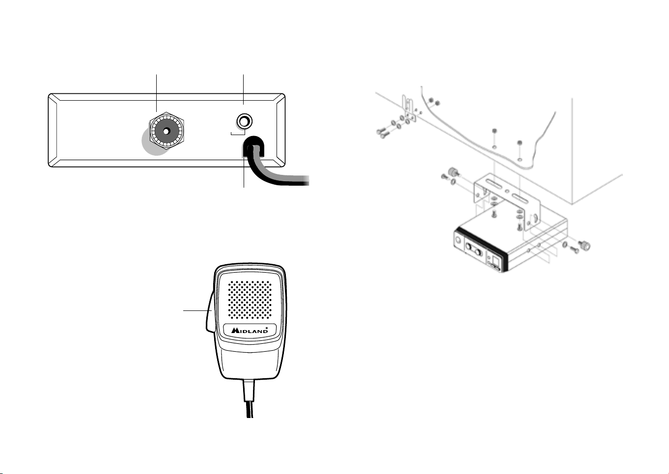
2. Controllare che l’antenna e il microfono siano ben connessi.
3. Posizionare il commutatore d’emergenza sulla posizione centrale.
4. Scegliere il modo di emissione AM o FM.
5. Girare la manopola squelch nella massima posizione antioraria.
6. Accendere l’apparato mediante la manopola ON/OFF/VOL.
7. Ricercare il canale desiderato attraverso i tasti CHANNEL.
8. Regolare il volume come desiderato.
9. Regolare lo squelch. Questo comando viene utilizzato per eliminare il rumore
di fondo del ricevitore in assenza di segnali d’ingresso. Per la massima sensibi-
lità del ricevitore è preferibile che il comando sia regolato solo al preciso livello
dove il rumore di fondo del ricevitore o il rumore ambientale, viene eliminato.
Girare completamente in senso antiorario poi lentamente in senso orario fin-
chè non scomparirà il rumore. Qualsiasi segnale anchè possa venir ricevuto,
dovrà essere leggermente più intenso rispetto alla media del rumore ricevuto.
Un’ ulteriore rotazione in senso orario aumenterà il livello di soglia che il segna-
le dovrà superare per poter essere udito. Se lo squelch sarà posizionato nella
massima posizione in senso orario, si potranno sentire solo segnali molto forti.
Trasmissione:
10. Selezionare il canale desiderato.
11. Premere il pulsante di trasmissione e parlare.
12. Per ricevere, rilasciare il pulsante di trasmissione.
N.B.: Gridare nel microfono non aumenta la portata della trasmissione, in quanto
un circuito interno automaticamente commuta la massima modulazione. Si consiglia
quindi di usare un tono di voce normale.
Canali prioritari (ch 9-19)
L’ALAN 100PLUS B è dotato di un commutatore che permette di posizionarsi
immediatamente sui canali 9 e 19. Il canale 9 serve solo per le comunicazioni di
emergenza. Il canale 19 invece è usato per richiedere informazioni sulla viabilità, ecc.
Posizionando l’interruttore nella posizione centrale si ritornerà all’ultimo canale se-
lezionato.
Altoparlante supplementare
Inserire un altoparlante con uscita da 3-10 W nella presa EXT-SPKR. In questo
modo l’altoparlante interno viene disconnesso.
CARATTERISTICHE TECNICHE
Ricevitore
Gamma di frequenza .....................................................................da 26.965 a 27.405
Sensibilità ............................................................migliore di 1.0 μV per 20 dB SINAD
Rejezione canali adiacenti .....................................60 dB (10 KHz); 70 dB (20 KHz)
Frequenze IF ............................................................ 1° IF=10.7 MHz; 2° IF=455 KHz
Potenza d’uscita audio ...................................................................................4.5 W max
Risposta in frequenza ....................................................................6 dB:450-2500 Hz
Squelch ..................................................................................regolabile da 1.2 μV a 1mV
Trasmettitore
Gamma di frequenza .....................................................................da 26.965 a 27.405
Ciclo di utilizzo.......................................................................................................5/5/90
Potenza d’uscita ................................................................................................4 W max
Modulazione ....................................................................................................... AM/FM
Deviazione massima ..................................................................2.5 KHz FM; 80% AM
Emissioni spurie .............................................................................................62 dB o più
Tolleranza di frequenza ............................................................................più di 0.002%
Alimentazione .........................................................................................................13.8 V
Corrente assorbita ........................................................................FM:1.3 A; AM: 1.8 A
Impedenza antenna ........................................................................................... 50 Ohm
Dimensioni ...........................................................................................124x38x190 mm
Peso ..........................................................................................................................1.2 kg
Le specifiche sono soggette a modifiche senza preavviso.


Alan 100 Plus B Instruction Guide | 1
CONTENTS
DESCRIPTION OF THE CONTROLS ................................................ 3
Front panel .............................................................................................. 3
Rear panel ...............................................................................................4
Microphone .............................................................................................4
INSTALLATION.......................................................................................... 5
Replacing fuse......................................................................................... 6
Antenna connection............................................................................... 6
Base station antenna................................................................................7
USING YOUR TRANSCEIVER............................................................... 8
Remote speaker operation..................................................................... 9
TECHNICAL SPECIFICATIONS............................................................. 9

2 | Alan 100 Plus B Instruction Guide Alan 100 Plus B Instruction Guide | 3
40 CHANNEL AM/FM MOBILE TRANSCEIVER
• Display with channel indicator
• Quick selection of emergency channels 9/19
• UP/DOWN controls
• Squelch for the background noise suppression
• Power cord with cigarette lighter plug included
• AM/FM selector
• Supply voltage from 12 to 13.8V
DESCRIPTION OF THE CONTROLS
Front panel
1. 4 pin microphone connector: insert the mic connector into this jack
2. ON/OFF – VOL: OFF position: radio switched o. Rotate the knob to adjust
the volume to the desired level
3. SQUELCH: this knob allows to eliminate the unwanted background noise.
4. CH9/19: selector for the quick access to emergency channels 9/19
5. Display: the channel in use will be shown
6. Led rx/tx: reception (rx) or transmission (tx) indicator
7. CHANNEL UP/DOWN: controls for channel selection
8. FM/AM: selector of the AM or FM mode
9
CH
19
40
TX
FM AM CHANNEL
EXT
ANT
SPKR
+
-
RED
BLK
40
RX
SQUELCH ON/OFF VOL
EXT
ANT
SPKR
+
-
RED
BLK
ALAN 100 PLUS
1 3 2 8 7
54 6
9
1110
12

4 | Alan 100 Plus B Instruction Guide Alan 100 Plus B Instruction Guide | 5
Rear panel
9. Power cord with 12V cigarette lighter plug.
10. Antenna connector: SO239 connector type.
11. EXT jack: external loudspeaker jack (the internal speaker will be excluded).
Microphone
12. PTT: transmission button
INSTALLATION
Safety and convenience are the primary considerations for mounting any piece of
mobile equipment. All controls must be readily available to the operator without
interfering with the movements necessary for safe operation of the vehicle. Be sure
all cables are clear of the brake, clutch and accelerator. Also, thought must be given
to the comfort of passengers.
Another extremely important requirement is the ease of installation and removal
for those occasions when you might want to remove the unit for service and main-
tenance.
The most common mounting position for a transceiver is under the dashboard di-
rectly over the drive shaft hump. Do not mount the transceiver in the path of the
heater or air conditioning. Take your time and plan your installation carefully. When
you have determined the best location for mounting, use the mounting bracket as a
template to mark mounting holes.
9
CH
19
40
TX
FM AM CHANNEL
EXT
ANT
SPKR
+
-
RED
BLK
40
RX
SQUELCH ON/OFF VOL
EXT
ANT
SPKR
+
-
RED
BLK
ALAN 100 PLUS
1 3 2 8 7
54 6
9
1110
12
9
CH
19
40
TX
FM AM CHANNEL
EXT
ANT
SPKR
+
-
RED
BLK
40
RX
SQUELCH ON/OFF VOL
EXT
ANT
SPKR
+
-
RED
BLK
ALAN 100 PLUS
1 3 2 8 7
54 6
9
1110
12
Washer
Machine screw
Machine screw
Washer
Washer
Machine screw
Nut
Hanger
Washer Machine screw
Tapping screw

6 | Alan 100 Plus B Instruction Guide Alan 100 Plus B Instruction Guide | 7
Take care when you drill the holes that you do not drill into wiring, trim or other
accessories.
Mount in position with bolts, lock washers and nuts or self-threading screws.Plug-in
the 12V power cord into the cigarette lighter plug. Connect the RED wire to the
(+) terminal and the BLACK wire to the (-) terminal. Connect the RED wire (with
in-line fuse holder) to the accessory terminal on the ignition switch of your vehicle.
Make a good mechanical and electrical connection to the frame of the vehicle for
the black wire. Before operation, you must install and connect your antenna system.
The lead from the antenna you’ve installed should be connected to the antenna
coaxial connector. If you are using an external speaker, connect it to the EXT-SPKR
jack.
Replacing fuse
Replace the fuse with a similar one with a value of 2A min.
Antenna connection
Connect the CB antenna to the ANT socket on the back of ALAN 100 PLUS B.
The antenna must be tuned to the CB radio band. For this use a SWR meter. For a
good radio range, the SWR should not exceed a value of 2. A high SWR also points
to defects in antenna, cable, or a short circuit in the antenna line.
Never transmit without connecting the antenna!
Note: The radio antenna is to be mounted from other antennas and interference
sources as much as possible. CB antennas must be mounted usually in the vehicule
highest part on a metal surfaces. A suciently large metal surface is essential for the
function of the antenna. For installation on a fiberglass cabs or plastic wind deflectors,
special ground less antennas can be used.
Base station antenna
While your transceiver is designed for mobile operation, you might
wish to use it as a base station unit, in conjunction with a 12 - 13.8 V
2 A DC power supply. If you decide to use your transceiver as a base
station, choose an antenna designed to operate most eciently as a
base station antenna. For example, the 1/2 wave antenna is a high-
eciency radiator with omnidirectional characteristics. It performs
as well in most applications as does the ground plane. You can use
this type of antenna for medium-long range communications.
13,8V DC
EXT
ANT
SPKR
+
-
RED
BLK
EXT
ANT
SPKR
+
-
RED
BLK

8 | Alan 100 Plus B Instruction Guide Alan 100 Plus B Instruction Guide | 9
USING YOUR TRANSCEIVER
Do not transmit without a suitable antenna or 50 Ohm load connected to the an-
tenna connector.
To receive:
1. Check that the unit is properly connected to a source of 12-13.8 V through
the in-line fuse and red wire.
2. Make sure that the antenna is attached.
3. Connect the mic plug to the mic jack.
4. Select AM or FM mode.
5. Set the emergency switch to the center position.
6. Set the Squelch control to maximum counterclockwise position.
7. Turn on the unit by rotating the ON/OFF/VOL control.
8. Set channel selector to the desired channel.
9. Adjust the volume to a suitable listening level.
10. Adjust Squelch to cut out annoying background noise when no signal is being
received.To do this, set the Channel Selector to a channel where no signals are
present or wait until signals cease on your channel.
Then, rotate the Squelch control in a clockwise direction to the point where the
background noise just stops. Now, when a signal is present, you will hear it, but will
not be disturbed by noise on the channel between signals.
When properly set, the Squelch keeps the receiver “dead” until a signal comes in on
that channel. However, do not set the Squelch too high, otherwise weak signals will
not be able to open the Squelch circuit. To receive very weak signals, it is best to lea-
ve Squelch set to the minimum position by rotating the control maximum counter-
clockwise. The Squelch circuit in your Transceiver is an advanced design. It uses an
operational amp IC to accomplish a hysteresis action. The result is that when you
set the Squelch for a precise signal level, if that signal level increases or decreases
in strength, the Squelch circuit will follow this change. With conventional Squelch
circuit, often a signal which changes strength get “chopped” by the Squelch circuit
and you lose a portion of the message.
With a hysteresis Squelch, you get it all.
To Transmit:
1. Select the desired channel.
2. Press the push-to talk button on the microphone and speak in a normal voice.
3. To receive, release the push-to-talk button.
Be sure the mic plug is firmly connected to the jack.
NOTE: shouting into the mic will not increase your power or signal. An internal circuit
automatically sets the mic signal for maximum modulation, so speaking loudly will give
no advantage.
Remote speaker operation
A 4 Ohm speaker, rated at 3-10 watts, should be used for this function. Plug the
speaker into the EXT SPKR jack at the rear of the transceiver. When the external
speaker is plugged in, the internal speaker is disconnected. You can now monitor all
incoming signals through your remote speaker.
TECHNICAL SPECIFICATIONS
Receiver
Frequency coverage ...............................................................26.965 to 27.405 MHz
Sensivity .............................................................better than 1.0 μV for 20 dB SINAD
Adjacent Channel Rejection ............................ 60 dB at 10 kHz; 70 dB for 20 KHz
Intermediate Frequency ......................................1st IF=10.7 MHz; 2nd IF=455 KHz
Audio Output power ................................................................................4.5 watts max
Frequency Response (-6dB) .................................................................450-2500 Hz
Squelch ...........................................................................adjustable from 1.2 μV to 1mV
Trasmitter
Frequency coverage ...............................................................26.965 to 27.405 MHz
Duty cycle..............................................................................................................5/5/90
Output Power ..............................................................................................4 watts max
Type of modulation ............................................................................................ AM/FM
Max Deviation ...........................................................................2.5 KHz FM; 80% AM
Spurious Radiation .................................................................................62 dB or better
Frequency Tolerance .................................................................... better than 0.002%
Antenna impedance ......................................................................................... 50 Ohm
Power supply ............................................................................................................13.8V
Current Drain ...............................................................................FM: 1.3 A; AM: 1.8 A
Dimensions ..........................................................................................124x38x190 mm
Weight ...................................................................................................................... 1.2 kg
Specifications are subject to change without notice.
The disconnect device shall disconnect both poles simultaneously.


Alan 100 Plus B Bedienungsanleitung | 1
INHALT
BEDIENELEMENTE BESCHREIBUNG.............................................. 3
Rückseite................................................................................................. 4
Mikrofon .................................................................................................4
INSTALLATION UND STROMANSCHLUSS.................................... 5
Montage der Mobilhalterung................................................................. 5
Stromanschluß........................................................................................ 6
Antennen-Anschluß................................................................................7
Niemals ohne Antenne senden!.............................................................7
Abstimmung der Antenne ..................................................................... 8
Externer Lautsprecher............................................................................ 8
BEDIENUNG ............................................................................................. 8
Einschalten/Lautstärke einstellen ......................................................... 8
Rauschsperre (Squelch) einstellen........................................................ 8
CB-Kanal einstellen................................................................................ 9
Empfangen und Senden......................................................................... 9
Kurzwahltaste für Kanal 9 und 19.......................................................... 9
Externer Lautsprecher............................................................................ 9
TECHNISCHE DATEN...........................................................................10

2 | Alan 100 Plus B Bedienungsanleitung Alan 100 Plus B Bedienungsanleitung | 3
40 KANAL AM/FM MOBILFUNKGERÄT
• Kanalanzeige
• Schnellauswahl für Notruf-Kanäle 9 und 19
• UP/DOWN Tasten Squelch: Unterdrückung der Hintergrundgeräusche
• Stromkabel mit Zigarettenanzünder-Stecker
• AM/FM Schalter
• Versorgungsspannung zwischen 12 und 13.8V
BEDIENELEMENTE BESCHREIBUNG
1. 4-poliger Mikrofonanschluss: stecken Sie hier das Mikrofon ein
2. ON/OFF – VOL: Position OFF: das Gerät ist ausgeschaltet. VOL: zum
Erhöhen oder Verringern der Lautstärke
3. SQUELCH-Knopf: stellen Sie die gewünschte Rauschunterdrückung ein
4. CH9/19: Notruf-Kanäle 9/19
5. Kanalanzeige
6. Led rx/tx: Empfangs (RX) / Sende (TX) Anzeige
7. CHANNEL UP/DOWN: Kanalwahltasten
8. AM/FM: zum Ändern von der AM- zur FM Modulationsart
9
CH
19
40
TX
FM AM CHANNEL
EXT
ANT
SPKR
+
-
RED
BLK
40
RX
SQUELCH ON/OFF VOL
EXT
ANT
SPKR
+
-
RED
BLK
ALAN 100 PLUS
1 3 2 8 7
54 6
9
1110
12

4 | Alan 100 Plus B Bedienungsanleitung Alan 100 Plus B Bedienungsanleitung | 5
Unterlegscheiben
Federscheiben
Maschinenschrauben
oder Blechschrauben
Schraube
Unterlegscheiben
Muttern
Muttern
Rändelschraube
Mobilhalterung
Rändelschraube
Schraube
Unterlegscheiben
Unterlegscheiben
Rückseite
9. Spannungsversorgung mit 12V Zigarettenanzünderbuchse
10. Antennenbuchse (SO239): hier wird der Stecker des Antennenkabels mit
dem Funkgerät verbunden
11. EXT-Anchluss: An diese Buchse kann ein externer Lautsprecher angesch-
lossen werden. Der eingebaute Lautsprecher schaltet sich dann automatisch
stumm
Mikrofon
12. PTT: Taste zum Senden
INSTALLATION UND STROMANSCHLUSS
Sie können Ihr ALAN 100PLUS B mit der beiliegenden Mobilhalterung in Ihrem
PKW befestigen. Für die Wahl eines geeigneten Platzes müssen Sie u.a. folgende
Punkte berücksichtigen:
Das Gerät darf die Bedienung des PKW in keiner Weise beeinträchtigen.
Es darf die Sicherheit aller Fahrgäste in keiner Weise beeinträchtigen.
Das Gerät darf nicht über längerer Zeit direkter Sonneneinstrahlung ausgesetzt
sein, da es sich sonst zu stark erwärmen könnte!
Aus dem selben Grund darf es nicht in der Nähe der Austrittsönungen für die
Heizluft montiert werden.
Suchen Sie einen Montageort, an dem Sie das Gerät gut bedienen können!
Montage der Mobilhalterung
• Überlicherweise wird das Funkgerät unter dem Armaturenbrett montiert.
• Benutzen Sie die beiliegende Mobilhalterung als Bohrschablone und markieren
Sie die beiden Befestigungspunkte.
• Überprüfen Sie Sorgfältig, daß Sie bei der Montage an dieser Stelle keine Bau-
teile oder Kabel hinter dem Armaturenbrett beschädigen!
• Bohren Sie mit einem Bohrer die beiden Löcher zur Befestigung der Mobilhal-
terung.
9
CH
19
40
TX
FM AM CHANNEL
EXT
ANT
SPKR
+
-
RED
BLK
40
RX
SQUELCH ON/OFF VOL
EXT
ANT
SPKR
+
-
RED
BLK
ALAN 100 PLUS
1 3 2 8 7
54 6
9
1110
12
9
CH
19
40
TX
FM AM CHANNEL
EXT
ANT
SPKR
+
-
RED
BLK
40
RX
SQUELCH ON/OFF VOL
EXT
ANT
SPKR
+
-
RED
BLK
ALAN 100 PLUS
1 3 2 8 7
54 6
9
1110
12

6 | Alan 100 Plus B Bedienungsanleitung Alan 100 Plus B Bedienungsanleitung | 7
• Schrauben Sie dann die Mobilhalterung mit den beiliegenden Schrauben fest.
• Befestigen Sie das Funkgerät so in der Mobilhalterung, daß die Rückseite des
Funkgerätes für die weiteren Anschlüsse zugänglich bleibt.
Nach dem Anschluß der Stromversorgung und der Antenne sowie eines eventuel-
len externen Lautsprechers fixieren Sie das Funkgerät in der Mobilhalterung:
• Seitliche Rändelschrauben in der gewünschten Position festziehen.
Stromanschluß
Ihre ALAN 100PLUS B wird mit 12-13,8 V Gleichspannung betrieben. Der Mi-
nuspol liegt am Gehäusechassis. Die Stromversorgung des Funkgerätes erfolgt mit
dem beiliegenden Stromversorgungskabel:
ROT = Pluspol, SCHWARZ = Minuspol (Masse).
In das rote Kabel ist eine Sicherung eingeschleift, die das Funkgerät vor Überla-
stung schützt. Brennt diese Sicherung durch, so müssen Sie erst die Ursache hierfür
ermitteln und beseitigen, bevor Sie die durchgebrannte Sicherung gegen eine des
gleichen Typs austauschen.
Sie haben verschiedene Möglichkeiten, das rote Stromversorgungskabel Ihres
ALAN 100PLUS B an den Pluspol des Bordnetzes anzuschließen:
• über den Sicherungskasten Ihres Autos,
• über die Zigarettenanzünder-Buchse,
• über das Zündschloß oder
• direkt an der Batterie.
Das schwarze Kabel schließen Sie an Masse oder direkt an den Minuspol der Bat-
terie an.
Antennen-Anschluß
Schliesen Sie die CB-Antenne an die ANT-Buchse auf der Rückseite des ALAN
100 PLUS B an.
Die Antenne muss auf das CB-Band abgestimmt sein. Verwenden Sie hierzu ein
SWR-Messgerät. Für eine gute Reichweite sollte das SWR den Wert 2 nicht
überschreiten. Ein hohes SWR weist auf Defekte in Antenne, Kabel oder einen
Kurzschluss in der Antennenleitung hin.
Senden Sie niemals ohne angeschlossene Antenne!
Hinweis: Die Funkantenne sollte so weit entfernt wie möglich von anderen Antennen
und Störquellen montiert werden. CB-Antennen sollten möglichst auf dem Dach des
Fahrzeugs montiert werden. Für die Funktion der Antenne ist eine ausreichend große
Metalloberfläche erforderlich. Zur Montage auf GFK-Auauten oder auf Kunststo-
Windabweisern sind spezielle massefreie Antennen verfügbar
Niemals ohne Antenne senden!
Senden Sie niemals ohne angeschlossene Antenne. Senden Sie auch dann nicht,
wenn das Verbindungskabel zwischen ALAN 100PLUS B und Antenne defekt sein
sollte. Sie könnten damit die Sender-Endstufe Ihres Funkgerätes beschädigen.
13,8V DC
EXT
ANT
SPKR
+
-
RED
BLK
EXT
ANT
SPKR
+
-
RED
BLK

8 | Alan 100 Plus B Bedienungsanleitung Alan 100 Plus B Bedienungsanleitung | 9
Abstimmung der Antenne
Fast alle CB-Antennen sind ab Werk auf den CB-Bereich abgestimmt.
Manche CB-Antennen lassen sich zusätzlich in ihrer Abstimmung op-
timieren. Folgen Sie hierbei der Anleitung des Antennen-Herstellers.
Externer Lautsprecher
Die beste Wiedergabe erzielen Sie mit einem externen Lautsprecher,
den Sie an passender Stelle in Ihrem Fahrzeug montieren. Er wird an der
rückseitigen Buchse EXT des Funkgerätes angeschlossen. Der interne
Lautsprecher schaltet dann automatisch ab.
BEDIENUNG
Einschalten/Lautstärke einstellen
In der Stellung “O” ist Ihr ALAN 100PLUS B ausgeschaltet. Durch
Drehen des Reglers im Uhrzeigersinn wird das Gerät eingeschaltet. Weiteres
Drehen im Uhrzeigersinn erhöht die Wiedergabelautstärke nach Wunsch.
Rauschsperre (Squelch) einstellen
Mit dem Regler Squelch stellen Sie die Empfangs-Signalstärke ein, ab der Sie
Stationen (oder Rauschen) im Lautsprecher hören.
Steht der Regler Squelch am linken Anschlag, so ist die Rauschsperre ausgeschaltet:
Auch auf einem völlig freien Kanal hören Sie im Lautsprecher Rauschen. Drehen
Sie den Regler Squelch weiter im Uhrzeigersinn, so schließt die Rauschsperre. Je
weiter Sie den Regler Squelch im Uhrzeigersinn drehen, umso stärker müssen die
Stationen sein, die Rauschsperre zu önen und im Lautsprecher hörbar zu werden.
Überlicherweise stellen Sie die Rauschsperre auf die höchste Empfindlichkeit ein,
so daß Sie auch bei schwachen Signalen önet, das allgemeine Rauschen aber nicht
zu hören ist:
• Schalten Sie das CB-Funkgerät ein.
• Drehen Sie den Regler Squelch auf den linken Anschlag.
• Stellen Sie mit den Kanalwahltasten einen freien Kanal ein, auf dem nur Rauschen
zu hören ist.
• Drehen Sie den Regler Squelch langsam so weit nach rechts, bis dieses Rau-
schen gerade verschwindet.
CB-Kanal einstellen
Den gewünschten CB-Kanal zwischen 1 und 40 stellen Sie mit dem Kanalwahltasten
ein. Der aktuelle Kanal erscheint im LED-Display.
Empfangen und Senden
Normalerweise befindet sich Ihr Funkgerät im Empfangsbetrieb.
Zum Senden drücken Sie die PTT-Taste auf der linken Seite des Mikrofons.
Sprechen Sie aus in das Mikrofon. Ihr Funkgerät befindet sich solange auf Sendung,
bis Sie die PTT-Tage des Mikrofons wieder loslassen. Während des Sendens leuchtet
die Sende-Anzeige.
Kurzwahltaste für Kanal 9 und 19
Ihr ALAN 100PLUS B verfügt über eine Kurzwahltaste, mit der Sie sofort die
Notruanäle 9 oder 19 aufrufen können.
Diese Umschaltung wird mit Schiebeschalter „9 CH 19“ vorgenommen.
• In Position 9 (oben) schaltet das Funkgerät sofort auf Kanal 9.
• In Position 19 (unten) schaltet das Funkgerät sofort auf Kanal 19.
• In Position CH (Mitte) können Sie mit den Tasten UP/DOWN einen beliebigen
Kanal zwischen 1 und 40 einstellen.
Hinweis: Die UP/DOWN Tasten sind gesperrt, wenn der Schalter auf Postion 9 oder
19 gestellt ist.
Externer Lautsprecher
Im ALAN 100PLUS B ist bereits ein Lautsprecher eingebaut. Sie können aber auch
einen externen Lautsprecher einsetzen und diesen an einer akustisch günstigen
Stelle im Auto montieren.
Der externe Lautsprecher wird an der Buchse EXT angeschlossen. Dabei schaltet
sich der interne Lautsprecher automatisch ab.
Der externe Lautsprecher muß eine Impedanz von 4-8.Ohm und eine Belastbarkeit
von min. 3 Watt aufweisen. Der Anschluß erfolgt über einen 3,5 mm Klinkenstecker
This manual suits for next models
1
Table of contents
Languages:
Other Midland Transceiver manuals

Midland
Midland 70-1545 User manual

Midland
Midland LMR 70-1526A User manual

Midland
Midland CT2000 Manual

Midland
Midland M Zero Manual

Midland
Midland 13-795 User manual

Midland
Midland CT 510 User manual

Midland
Midland ALAN 8001S EURO User manual

Midland
Midland 77-104XL User manual

Midland
Midland 70-3350 User manual

Midland
Midland M24-S User manual

Midland
Midland G10 Manual

Midland
Midland CT 890 Manual

Midland
Midland CT990 Manual

Midland
Midland CT990 Manual

Midland
Midland CT 890 User manual

Midland
Midland CT590S User manual

Midland
Midland Alan 48 Pro Manual

Midland
Midland XT50 PRO User manual

Midland
Midland CT 510 User manual

Midland
Midland 88 User manual