TIL TST-4100 92-SC User manual

VHF/AM SINGLE CHANNEL
TRANSMITTERS Model TiL-92-SC
25 WATT TX, P/N 931037-1 TST-4100
15 WATT TX, P/N 931038-1 TST-4200
LOW POWER TX, P/N 931039-1 TST-4300
Installation and
Operating Instructions
TiL Document No. 93RE126
Rev. F
AUGUST 2012
Technisonic Industries Limited
240 Traders Boulevard, Mississauga, Ontario L4Z 1W7
Tel: (905) 890-2113 Fax: (905) 890-5338
www.til.ca
Copyright by Technisonic Industries Limited. All rights reserved.

ii
REVISION HISTORY
[ 93RE126 ]
REV SECTION
- PAGE - DESCRIPTION DATE
Edited
by
n/c Original Document
A-C
D Global New Document Template (new file format)
Title page changed, Headers/Footers added
Added Revision page, Added Warranty page
2-5 Added note to §2.5 Channel Freq. Selection referring
to units built after Jan 2012 with a USB port and
added Appendix A (TDP-90 for USB AM units) with
Installation and Operating Instructions.
2-12,13 updated Fig 2.3 & 2.4 FEB 2012 FM
E 2-10 Table 2.4 Note: SW2 must be in Land Line position
2-12 Fig 2.3 updated as per Doc #106516 Rev B APR 2012 FM
F Title Pg Simplify System description
iii Updated FCC information including antenna and
FCC labeling instructions.
Simplify description under “Warning”
Global “7 Watt” changed to “Low Power”
1-5 Revise Transmitter Characteristics for FCC and ICAN
information
2-5 Updated para 2.3
2-10, 2-12
Revised as per Test Procedure 106516 Rev C AUG 2012 FM

iiii

iii
WARNING
Do not make physical contact with antenna when transmitter is on.
CAUTION ! STATIC SENSITIVE !
This unit contains static sensitive devices. Wear a grounded wrist strap and/or conductive gloves
when handling printed circuit boards.
FCC COMPLIANCE INFORMATION
This device complies with Part 15 of the FCC Rules. Operation is subject to the following two conditions:
(1) this device may not cause harmful interference and (2) this device must accept any interference
received, including interference that may cause undesired operation.
WARNING: For compliance with FCC RF Exposure Requirements the transmitter antenna
installation shall comply with the following two conditions:
1.The transmitter antenna gain shall not exceed 3 dBi.
2. The transmitter antenna is required to be located outside of a vehicle and kept at a separation distance of 90 cm
or more between the transmitter antenna of this device and person(s) during operation.
NOTE: This equipment has been tested and found to comply with the limits for a Class A digital device,
pursuant to Part 15 of the FCC Rules. These limits are designed to provide reasonable protection against
harmful interference when the equipment is operated in a commercial environment. This equipment
generates, uses, and can radiate radio frequency energy and, if not installed and used in accordance with
the instruction manual, may cause harmful interference to radio communications. Operation of this
equipment in a residential area is likely to cause harmful interference, in which case the user will be
required to correct the interference at his/her own expense.
FCC LABELING INFORMATION: When this device is permanently mounted in an enclosure where the
FCC ID label can not be seen, another label must be placed on the outside of the enclosure stating
‘contains FCC ID: IMA90-6R’.
WARRANTY INFORMATION
The Model 92-SC series, Rack Mounted Single Channel Transmitters, are under warranty for one year
from date of purchase. Failed units caused by defective parts, or workmanship should be returned to:
Technisonic Industries Limited
240 Traders Boulevard
Mississauga, Ontario L4Z 1W7
Tel: (905) 890-2113
Fax: (905) 890-5338

iv

TECHNISONIC INDUSTRIES LIMITED
www.til.ca
TST-4x00 92-SC Installation & Operating Instructions TiL 93RE126 Rev F
v
TABLE OF CONTENTS
SECTION TITLE PAGE
SECTION 1 GENERAL DESCRIPTION
1.1 INTRODUCTION ............................................................................................................... 1-1
1.2 DESCRIPTION .................................................................................................................. 1-1
1.2.1 Transmitter Module ........................................................................................................... 1-2
1.2.2 Power Supply Modules - Models SPG-007, SPG-015, SPG-025 ..................................... 1-2
1.2.3 RF Amplifier Modules - Models PA-15, PA-25 .................................................................. 1-2
1.2.4 Mother Board ..................................................................................................................... 1-2
1.2.5 Remote Control Boards ..................................................................................................... 1-2
1.2.6 RF Isolator (Option 2) ........................................................................................................ 1-3
1.3 MODES OF OPERATION ................................................................................................. 1-3
1.3.1 Local/Remote Operation ................................................................................................... 1-3
1.3.1.1 Conference Audio ............................................................................................................. 1-3
1.3.2 AC and DC Operation ....................................................................................................... 1-4
1.4 TECHNICAL SUMMARY .................................................................................................. 1-4
SECTION 2 PREPARATION FOR USE AND STORAGE
2.1 INTRODUCTION ............................................................................................................... 2-1
2.2 DISASSEMBLY/ASSEMBLY ............................................................................................ 2-1
2.2.1 Remove/Replace Cover Assembly ................................................................................... 2-1
2.2.2 Remove/Replace Transmitter Module .............................................................................. 2-1
2.2.3 Remove/Replace Memory Set Board Module A5A1 ......................................................... 2-3
2.2.4 Remove/Replace Control Board ....................................................................................... 2-3
2.3 CHANNEL FREQUENCY SELECTION ............................................................................ 2-5
2.3.1 Introduction ........................................................................................................................ 2-5
2.3.2 Frequency Range .............................................................................................................. 2-5
2.3.3 Pre-Programming Channel Frequency ............................................................................. 2-5
2.3.4 Offset Frequency Set ........................................................................................................ 2-5
2.4 REMOTE OPERATION SET UP ....................................................................................... 2-9
2.4.1 Remote Control Board P/N 923051-1 ............................................................................... 2-10
2.4.2 Remote Control Board P/N 940180-1 ............................................................................... 2-11
2.5 TRANSMITTER ADJUSTMENTS AND SETTINGS ......................................................... 2-14
2.6 OPERATIONAL CHECK ................................................................................................... 2-14
2.7 STORAGE ......................................................................................................................... 2-14
SECTION 3 OPERATING INSTRUCTIONS
3.1 INTRODUCTION ............................................................................................................... 3-1
3.2 INSTALLATION ................................................................................................................. 3-1
3.3 OPERATOR'S SWITCHES, CONTROLS AND INDICATORS ......................................... 3-1
3.4 OPERATING INSTRUCTIONS ......................................................................................... 3-4
3.4.1 Transmitter Operation (Local Mode) ................................................................................. 3-4
3.4.2 Switching OFF ................................................................................................................... 3-5
3.4.3 External DC Operation ...................................................................................................... 3-5
WARRANTY ..........................................................................................................................................
Appendix A.. TDP-90 Programming Software User’s Guide (for USB) ................................................ A-1

TECHNISONIC INDUSTRIES LIMITED
www.til.ca
TST-4x00 92-SC Installation & Operating Instructions TiL 93RE126 Rev F
vi
LIST OF FIGURES
FIGURE TITLE PAGE
1.1 VHF/AM Single Channel Transmitter ....................................................................................... 1-1
2.1 Single Channel Transmitter - Internal View .............................................................................. 2-2
2.2 Single Channel Memory Set Board - Module A5A1 ................................................................. 2-4
2.3 Remote Control Board P/N 923051-1 ...................................................................................... 2-12
2.4 Remote Control Board P/N 943180-1 ...................................................................................... 2-13
2.5 Transmitter Adjustments and Settings ..................................................................................... 2-15
3.1 Single Channel Transceiver Controls and Indicators ............................................................... 3-2
LIST OF TABLES
TABLE TITLE PAGE
1.1 92-SC Leading Particulars ....................................................................................................... 1-5
2.1 Frequency Selection MHz ........................................................................................................ 2-6
2.2 Frequency Selection kHz ........................................................................................................ 2-7
2.3 Remote Control Connector Functions ...................................................................................... 2-9
2.4 Remote Control Board P/N 923051-1 Settings ........................................................................ 2-10
2.5 Remote Control Board P/N 943180-1Settings ......................................................................... 2-11
3.1 Operator's Switches, Controls and Indicators .......................................................................... 3-3

TECHNISONIC INDUSTRIES LIMITED
www.til.ca
TST-4x00 92-SC Installation & Operating Instructions TiL 93RE126 Rev F
1-1
SECTION 1 - GENERAL DESCRIPTION
1.1 INTRODUCTION
This publication provides general information on the VHF/AM Single Channel Transmitters, Model
TiL-92-SC, Part Nos. 931037-1, 931038-1, and 931039-1 manufactured by Technisonic
Industries Limited. These units are also referred to by Item No.'s TST-4100, TST-4200 and TST-
4300 respectively.
The Model TiL-92-SC Transmitters are single channel, fixed frequency transmitters operating
over the frequency range of 117.975 MHz to 138.000 MHz. These units are intended for base
station operation in an air traffic environment. These systems can operate from AC power or
external DC power in local and remote operating modes.
1.2 DESCRIPTION
The three rack mounted transmitter configurations are based on the Model 90-6R pre-
programmable transceiver module, modified for transmit only operation. All systems can be
optionally configured for 2 Wire mode with Current, or Tone remote control operation. Each
configuration consists of a Power Supply Module, Mother Board, and Control Board. The 15 Watt
and 25 Watt configurations also consist of an RF Linear Amplifier Module.
The TST series transmitters now come standard with an RF Isolator which provides unidirectional
coupling to the antenna in multiple transmitter configurations.
Figure 1.1 VHF/AM Single Channel Transmitter

TECHNISONIC INDUSTRIES LIMITED
www.til.ca
TST-4x00 92-SC Installation & Operating Instructions TiL 93RE126 Rev F
1-2
1.2.1 Transmitter Module
The Single Channel Transmitter is based on Transceiver Model 90-6R, modified for transmit only
operation. The transmitter module is a low power VHF/AM transmitter which can transmit on a
single pre-programmable synthesized frequency, with 25 kHz channel spacing in the frequency
range 117.975 MHz to 138.000 MHz. The single channel memory set board, module A5A1 is
mounted external to the transmitter module to facilitate ease of frequency programming.
1.2.2 Power Supply Modules - Models SPG-007, SPG-015, SPG-025
The Power Supply Modules provide the DC supply voltage to the transmitter and linear amplifier,
and houses a battery charger which can provide charging and trickle charging to external
rechargeable batteries. Model SPG-007 is for use in the Low Power configurations, Model SPG-
015 is for use in the 15 Watt configurations, Model SPG-025 is for use in the 25 Watt
configurations.
1.2.3 RF Amplifier Modules - Models PA-15, PA-25
The RF Amplifier modules provide 15 Watt (Model PA-15) or 25 Watt (Model PA-25) power
output. The RF Amplifiers are fed by the Low Power RF output from the transmitter module.
1.2.4 Mother Board
The Mother Board provides all interconnection between the two external remote control
connectors, RF Amplifier Module, Power Supply, Remote Control Board, and Transmitter. The
Remote Control Board, RF Isolator and all internal fuses are mounted on the Mother Board.
1.2.5 Remote Control Boards
1. Line Interface Board P/N 923051-1
Provides remote control transceiver operation on 2 wire or 4 wire 600 ohm lines. This
board can be configured to key the transmitter using a 2175 Hz* continuous tone (see
below), plus/minus DC Voltages, ground keying and internal or external DC (15 mA)
current loop keying. Transmit audio is user selectable for two wires or four wires.
*Crystals for tone frequencies other than 2175 Hz may be obtained by special order (i.e.
2380 Hz).
2. Line Interface Board P/N 943180-1
Provides remote control transmitter operation on 2 wire dedicated 600 ohm lines utilizing
the EIA multi-tone keying format found in the Land Mobile Industry. A high level 2175
tone followed by a 1950 Hz guard tone and then a low level 2175 Hz continuous tone is
utilized to key the transceiver. The 943180-1 board can also be jumper strapped for
standard aeronautical 2175 Hz continuous tone operation. DC (15mA) current loop and
ground keying is also supported. However this board does not support 4 wire operation.
NOTE: P/N 923051-1 is the default board supplied in all units. The EIA multi-tone board P/N
943180-1 must be special ordered. To determine which remote card your 92-SC has installed the
Configuration label on the side of the rack mount chassis should be consulted.

TECHNISONIC INDUSTRIES LIMITED
www.til.ca
TST-4x00 92-SC Installation & Operating Instructions TiL 93RE126 Rev F
1-3
1.2.6 RF Isolator (Now standard on all units)
The RF Isolator is a broadband (118 MHz - 138 MHz) RF directional coupler. The RF Isolator
provides 20 dB of isolation between the antenna and RF Amplifier while providing 0.7 dB (Max.)
insertion loss.
1.3 MODES OF OPERATION
1.3.1 Local/Remote Operation
The Single Channel Transmitter can be operated in Local or Remote modes.
NOTE: Local operation is not disabled when operating in Remote mode and Remote operation is
not disabled when operating in Local mode. The two operating modes operate in parallel.
1. LOCAL OPERATION - In local operation, voice audio, and keying (PTT) functions are
routed from the microphone (not supplied) to the transmitter.
2. REMOTE OPERATION - In Remote operation, transmit audio and keying (PTT) functions
are routed over land lines to the 600 ohm remote inputs. Internal jumpers can be set for
±DC, ground, or tone transmitter keying, and to provide a RF Output Power signal
depending on the remote control board installed. Transmit audio is also routed to the
internal loudspeaker at an externally (high/low switch) adjustable preset level (see
conference audio).
1.3.1.1 Conference Audio
Conference Audio provides the operator with Tx voice on the transmitter speaker when the
transmitter is remotely keyed from another location. A 3-position high-off-low switch is provided to
externally control Tx audio levels. The Low position results in a 20dB lower audio level than when
the switch is in the High position.
The audio level of the transmit audio is internally adjustable from 0.0W to 0.5W of audio output.
The adjustment is performed via rotation of the potentiometer R7 (see Figure 2.6 for location),
which is accessible from the top of the transceiver after removing the top dust cover of the unit.
NOTE: The transmit audio level can be increased by rotating potentiometer R7clockwise and
decreased by counterclockwise rotation. If further adjustment of conference audio is required, the
top cover of the transmitter module must be removed to gain access to potentiometer R63,
located on the Audio Interface Module, A3 (see Figure 2.6 for location).

TECHNISONIC INDUSTRIES LIMITED
www.til.ca
TST-4x00 92-SC Installation & Operating Instructions TiL 93RE126 Rev F
1-4
1.3.2 AC and DC Operation
The units can be operated by external 120/220 VAC or external 28 VDC (13.7 VDC for Low
Power configurations).
1. AC OPERATION - During AC operation, the unit can charge and trickle charge external
batteries via the external connectors mounted on the rear panel of the unit. Refer to
Table 1.2 for details.
DC OPERATION - The unit can be operated from an external DC supply within the range
of 21.6 Vdc to 30 Vdc for 15 watt and 25 watt configurations and within the range of 11.5
Vdc to 15.0 Vdc for Low Power configurations.
1.4 TECHNICAL SUMMARY
A summary of electrical, operational, mechanical and physical characteristics of the Single
Channel Transmitters are provided in Table 1.1.

TECHNISONIC INDUSTRIES LIMITED
www.til.ca
TST-4x00 92-SC Installation & Operating Instructions TiL 93RE126 Rev F
1-5
TABLE 1.1 LEADING PARTICULARS - TST-4100/4200/4300
POWER REQUIREMENTS:
*Low Power Transmitter
AC Input Voltage/Current ……………………………………. 100 to 132 VAC @ 1.0 Amp
DC Input Voltage/Current ……………………………… 11.5 VDC to 15 VDC @ 3.5 Amp
15 Watt Transmitter
AC Input Voltage/Current ………………………………….… 100 to 132 VAC @ 1.5 Amp
DC Input Voltage/Current ……………………………… 21.6 VDC to 30 VDC @ 4.0 Amp
25 Watt Transmitter
AC Input Voltage/Current ………………………………….… 100 to 132 VAC @ 2.0 Amp
DC Input Voltage/Current ……………………………… 21.6 VDC to 30 VDC @ 7.5 Amp
NOTE: 220V operation is selectable by internal power supply jumper. Tolerances are 190 to 250 VAC
@ one-half the applicable current consumption in the 110 VAC mode.
POWER OUTPUT:
*Power Output (FCC) ..............................................…………………………...…… 10 Watts MAX
*Power Output (ICAN) ……………………………………..…………………………… 8 Watts MAX
15 Watt Transmitter ………………………………………………………………….… 15 Watts MAX
25 Watt Transmitter ……………………………………………………………………. 25 Watts MAX
Microphone Compression Range ………………………………………………………………………… 35 dB
Battery Charger Voltage & Current ……………………………………………..… 27.5 Vdc, 3.5 Amps MAX
REMOTE CONTROL:
Remote Audio Input ………………………………………………….……....… 2 wire, balanced 600 lines
Remote Tx Timeout ………………………………………………………………………… 30 to 300 seconds
Tone Keying:
Impedance ……………………………………………………..……… 600 floating with respect to ground
Tx Control Tone ……………………………………………………………… Selectable 1800 Hz to 3000 Hz
Tx Tone Input Level ………………………………………………………………………………. 0 to -40 dBm
Tx Tone Control Response Time …………………………………………………………… <12 milliseconds
DC Keying ……………………………………………………………………………………………….. ±48 Vdc
Loop Resistance …………………………………………………………………………………… 10K MAX
Ground Keying …………………………………………………………………………….… Closure to Ground
Loop Resistance ……………………………………………………………………………………. 4 K MAX
TX Interface Signals:
TX RF Output Signal ………………………………………….……. RF ON=Ground, RF OFF=Open Circuit
Temperature & Humidity:
Operating Temperature Range …………………………………… -25°C(-13°F) to +55°C(+131°F)
Storage Temperature Range ……………………………………… -55°C(-67°F) to +65°C(+149°F)
Relative Humidity ………………………………………………………………………………… 100%
Dimensions & Weight:
Width …………………………………………………………………………… 483 mm (19.0 in) MAX
Height …………………………………………………………………………...… 89 mm (3.5 in) MAX
Depth …………………………………………………………………………… 432 mm (17.0 in) MAX
Weight ……………………………………………………………………..……… 6.3 Kg (14 lbs) MAX

TECHNISONIC INDUSTRIES LIMITED
www.til.ca
TST-4x00 92-SC Installation & Operating Instructions TiL 93RE126 Rev F
1-6
TABLE 1.1 LEADING PARTICULARS - TST-4100/4200/4300 (Continued)
TRANSMITTER MODULE:
Dimensions & Weight:
Width …………………………………………………………………………..… 216 mm (8.5 in) MAX
Height ……………………………………………………………………………. 70 mm (2.75 in) MAX
Depth …………………………………………………………………………. 260 mm (10.25 in) MAX
Weight ………………………………………………………………………… 1.8 Kg (3 lb 15 oz) MAX
TECHNICAL:
Power Output (TX module w/o PA) …………………………………………………….… 5-10 Watts
Audio Input …………………………………………………………………….. 0.05 Vrms to 2.0 Vrms
Speech Processor Dynamic Range ………………………………………………………….… 35 dB
Modulation …………………………………………………………………………………… 95% MAX
Audio Distortion @ 90% mod (Low Power) ………………………………………………. 10% MAX
Audio Distortion @ 90% mod (with Linear Amplifier at High Power) ………………..… 15% MAX
Audio Frequency Response ………………………………………… 300 Hz to 2,500 Hz, +1 -3 dB
Spurious Emissions ……………………………………………………………… 60 dB below carrier
Hum and Noise ……………………………………………………… 45 dB below modulated carrier

TECHNISONIC INDUSTRIES LIMITED
www.til.ca
TST-4x00 92-SC Installation & Operating Instructions TiL 93RE126 Rev F
2-1
SECTION 2 – PREPARATION FOR USE AND STORAGE
2.1 INTRODUCTION
This section provides the information required for custom configuration and storage of the Single
Channel Transmitter. Custom system configuration includes customizing the remote control board
functions and the transmit frequency selection.
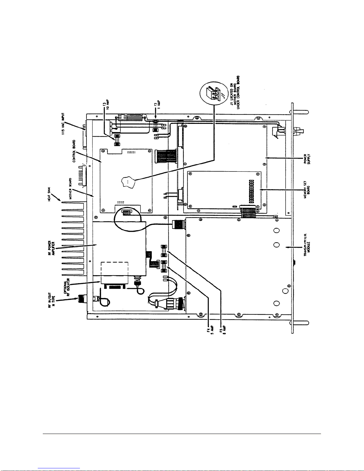
2.2 DISASSEMBLY/ASSEMBLY (Refer to Figure 2.1)
2.2.1 Remove/Replace Top Dust Cover Assembly
REMOVAL
(1) Remove and retain twelve screws securing top dust cover to the 19" rack chassis.
(2) Please note the location of the three longer screws which travel through the heatsink
shims riveted to the inside of the top cover.
(3) Lift cover clear of chassis to expose internal view of transmitter as shown in Figure 2.1.
REPLACEMENT
(1) Position top cover on chassis.
(2) Position one screw in each corner of the top-cover mounting holes. Place the three
longer screws into their correct holes located over the internal transmitter module.
(3) Secure cover to chassis with remaining screws.
2.2.2 Remove/Replace Transmitter Module
REMOVAL
(1) Remove dust cover as described in paragraph 2.2.1.
(2) Disconnect RF and DC connectors from rear of transmitter module.
(3) Remove and retain the screws securing the top cover of the internal transmitter module.
(4) Remove and retain two screws and two washers securing flat cable to the side of the
transmitter module and disconnect the flat cable. Disconnect the flat cable running out of
the transmitter module at the connector on the external memory set board.
(5) Remove and Retain four countersunk screws securing transmitter module to front panel.
(6) Move the transmitter module slightly back from the front panel and disconnect the flat
cable connecting the front panel assembly to the transmitter module, audio interface
board A3. The connector is located on the A3 board.
(7) Lift transmitter module clear of chassis.
TECHNISONIC INDUSTRIES LIMITED
www.til.ca
TST-4x00 92-SC Installation & Operating Instructions TiL 93RE126 Rev F
2-2
Figure 2.1 Single Channel Transmitter - Internal View

TECHNISONIC INDUSTRIES LIMITED
www.til.ca
TST-4x00 92-SC Installation & Operating Instructions TiL 93RE126 Rev F
2-3
REPLACEMENT
(1) Position the transmitter module into the chassis. While holding the transmitter module
slightly back from the front panel, re-connect the flat cable from the front panel to the A3
board in the transmitter module.
(2) Position and secure transmitter module to front panel with four countersunk screws.
(3) Connect flat cable to transmitter module. Secure flat cable to transmitter module with two
screws and two washers. Connect flat cable running out of the transmitter module to the
external memory set board.
(4) Connect DC and RF connectors to rear of transmitter module.
(5) Replace and secure the top cover of the transmitter module with the screws removed in
step (3) of the REMOVAL instructions.
(6) Replace top dust cover as described in paragraph 2.2.1
2.2.3 Remove Replace External Single Channel Memory Set Module A5A1
REMOVAL
(1) Remove dust cover as described in paragraph 2.2.1.
(2) Remove and retain four screws securing Memory Set Board, Module A5A1 "piggy back"
to the standoffs on the power supply cover. (See Figure 2.1 for location)
REPLACEMENT
(3) Secure the Memory Set Module to the stand-offs located on the power supply cover by
the four screws.
2.2.4 Remove/Replace Control Board
REMOVAL
(1) Remove dust cover as described in paragraph 2.2.1.
CAUTION: Care must be taken when removing or replacing Control Board to avoid
damage to Motherboard Connector Pins.
(2) Remove and retain four screws securing Control Board "piggy back" to the Mother Board
standoffs. Remove Control Board from Mother Board.
REPLACEMENT
(1) Align the two female connectors on the control board with the male connectors on the
Mother Board using the four mounting holes and standoffs as a guide. Secure control
board to the Mother Board standoffs with four screws and washers.
(2) Replace dust cover as described in paragraph 2.2.1.

TECHNISONIC INDUSTRIES LIMITED
www.til.ca
TST-4x00 92-SC Installation & Operating Instructions TiL 93RE126 Rev F
2-4
Figure 2.2 Single Channel Memory Set Module A5A1 - Component Layout

TECHNISONIC INDUSTRIES LIMITED
www.til.ca
TST-4x00 92-SC Installation & Operating Instructions TiL 93RE126 Rev F
2-5
2.3 CHANNEL FREQUENCY SELECTION
Early radios have their frequencies programmed by a diode matrix as
described in Section 2.3.3. For radio units shipped after July 2012 and
equipped with a USB port, please refer to Appendix A (TiL TDP-90
Programming Software User’s Guide for USB Programmable AM Series
Transceivers) - Document 11RE439.
2.3.1 Introduction
Before programming a new operating frequency, perform an operational check, as outlined in
Section 3. If there is any operational deficiency or equipment malfunction, return transmitter to the
manufacturer. Before use it is necessary to pre-program the operating frequency.
2.3.2 Frequency Range
The operating frequency may be programmed over the frequency range 117.975 MHz to 138.000
MHz with 25 kHz channel spacing.
2.3.3 Pre-programming Channel Frequency
Determine the operating frequency to be programmed and proceed as follows:
FREQUENCY SELECTION MHz.
Refer to Table 2.1 Frequency Selection MHz. Using the OPERATING FREQUENCY (MHz)
column, find the desired frequency in MHz. Cross-refer to the JUMPER LOCATION column, and
install the jumper as required.
FREQUENCY SELECTION KHz
Refer to Table 2.2, Frequency Selection kHz. Using the OPERATING FREQUENCY kHz column,
find the portion of the desired frequency in kHz. Cross-refer to the JUMPER LOCATION column,
and install the jumpers in the locations as required.
2.3.4 Offset Frequency Set
(A) Jumper J15, located on the single channel memory set board, module A5A1 selects the
frequency offset as follows:
(1) If J15 is not installed, frequency offset is inhibited.
(2) If J15 is installed in the Rx position, the transmit frequency will be offset high.
(3) If J15 is installed in the Tx position, the transmit frequency will be offset low.
(B) Trim capacitors C16 and C37, accessible from the bottom of the unit (see Figure 2.5), are
used to accurately adjust the transmit frequency. For the Tx frequency to be higher than
the receive frequency, proceed as follows:

TECHNISONIC INDUSTRIES LIMITED
www.til.ca
TST-4x00 92-SC Installation & Operating Instructions TiL 93RE126 Rev F
2-6
TABLE 2.1 FREQUENCY SELECTION MHz
JUMPER LOCATION
OPERATING
FREQUENCY
(MHz) 20 MHz 10 MHz 8 MHz 4 MHz 2 MHz 1 MHz
117 0 1 0 1 1 1
118 0 1 1 0 0 0
119 0 1 1 0 0 1
120 1 0 0 0 0 0
121 1 0 0 0 0 1
122 1 0 0 0 1 0
123 1 0 0 0 1 1
124 1 0 0 1 0 0
125 1 0 0 1 0 1
126 1 0 0 1 1 0
127 1 0 0 1 1 1
128 1 0 1 0 0 0
129 1 0 1 0 0 1
130 1 1 0 0 0 0
131 1 1 0 0 0 1
132 1 1 0 0 1 0
133 1 1 0 0 1 1
134 1 1 0 1 0 0
135 1 1 0 1 0 1
136 1 1 0 1 1 0
137 1 1 0 1 1 1
138 1 1 0 0 0 0
LEGEND:
0 = JUMPER BETWEEN CENTRE AND 0 1 = JUMPER BETWEEN CENTRE AND 1
This manual suits for next models
2
Table of contents
Popular Transmitter manuals by other brands


Lectroso
Lectroso smd instruction manual

Oppermann Regelgeräte
Oppermann Regelgeräte DDS-AR984 Series manual

Camille Bauer
Camille Bauer KINAX N705-MEMS operating manual

Rae
Rae RAEGuard EC user guide

Mitsubishi Electric
Mitsubishi Electric PAC-SF46EPA installation manual

Nasacom
Nasacom TV-WATCH instruction manual


