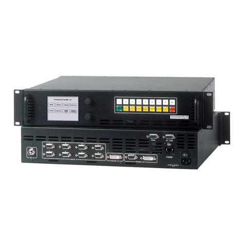
Timax 201R User manual

User Manual
w ww . o utbo ar d.c o .u k
Software Version
201R
&
269S

2
Table of Contents
Quick Start ..................................................................................................................................................................... 4
Hardware ........................................................................................................................................................................ 6
System Block Diagram............................................................................................................................................................................................. 7
Audio Inputs & Outputs ........................................................................................................................................................................................... 8
Analogue I/O interface......................................................................................................................................................................................... 8
Mixed AES3 Digital I/O and Analogue Output interface (MIO)...................................................................................................................... 8
MIO Board Installation & Configuration............................................................................................................................................................ 9
Optional Networked and Multi-channel Audio Interface .................................................................................................................................... 10
TiMax II MADI Interface Configuration.......................................................................................................................................................... 11
TiMax II Cobranet Interface Configuration...................................................................................................................................................... 13
Control Inputs & Outputs....................................................................................................................................................................................... 14
Ethernet ............................................................................................................................................................................................................... 14
Manual Network Configuration using fixed IP addresses ............................................................................................................................... 14
GPIO Input.......................................................................................................................................................................................................... 15
GPIO Output ....................................................................................................................................................................................................... 16
MIDI.................................................................................................................................................................................................................... 16
Front Panel Controls............................................................................................................................................................................................... 17
Group Faders & Mute ........................................................................................................................................................................................ 17
Channel Meters & Mute..................................................................................................................................................................................... 17
Select a Show...................................................................................................................................................................................................... 17
Select a Preset ..................................................................................................................................................................................................... 17
IP Address........................................................................................................................................................................................................... 17
Setup & Information........................................................................................................................................................................................... 17
Get out of Jail Free ............................................................................................................................................................................................. 18
High Reliability Options ........................................................................................................................................................................................ 19
Dual Mirrored Hard Disk Drives....................................................................................................................................................................... 19
Dual Power Supply and cooling fan.................................................................................................................................................................. 19
Bypass ................................................................................................................................................................................................................. 19
Software controller ...................................................................................................................................................... 20
Overview ............................................................................................................................................................................................................. 20
Password Protection ........................................................................................................................................................................................... 21
General Settings and Toolbar Controls ............................................................................................................................................................. 22
File management................................................................................................................................................................................................. 23
Live Control ................................................................................................................................................................. 24
Input and output control buttons........................................................................................................................................................................ 24
Source Mix.......................................................................................................................................................................................................... 25
Input Channel...................................................................................................................................................................................................... 26
Input Equaliser.................................................................................................................................................................................................... 27
Matrix.................................................................................................................................................................................................................. 28
Output Channel................................................................................................................................................................................................... 29
Output Equaliser ................................................................................................................................................................................................. 30
Group Masters .................................................................................................................................................................................................... 31
Programmed Control ................................................................................................................................................... 32
Files ..................................................................................................................................................................................................................... 32
Show store and recall.............................................................................................................................................................................................. 33
Create New Show Online................................................................................................................................................................................... 33
Create New Show Offline.................................................................................................................................................................................. 33
Open Selected Show on TiMax Disk ................................................................................................................................................................ 33
Open Show Online ............................................................................................................................................................................................. 33
Open Show Offline............................................................................................................................................................................................. 33
Save Show........................................................................................................................................................................................................... 33
Save Show As .. .................................................................................................................................................................................................. 34
EQ Library ......................................................................................................................................................................................................... 34
Routing Library .................................................................................................................................................................................................. 35
Preset store and recall ............................................................................................................................................................................................. 36
Recall Preset ....................................................................................................................................................................................................... 36
New Preset .......................................................................................................................................................................................................... 36
Update Preset ...................................................................................................................................................................................................... 36
System Preset...................................................................................................................................................................................................... 37
Programming Fade in and Fade out Times....................................................................................................................................................... 38
Sound File Playback Commands....................................................................................................................................................................... 39
Programming Time of Day Triggers ................................................................................................................................................................. 40
Setting Real Time Clock .................................................................................................................................................................................... 40
MIDI triggers ...................................................................................................................................................................................................... 40

3
Using Multiple Controllers ................................................................................................................................................................................ 41
Things to do if things go wrong.................................................................................................................................. 42
S – Version software ................................................................................................................................................... 43
Introduction......................................................................................................................................................................................................... 43
Overview ............................................................................................................................................................................................................. 43
File Management ................................................................................................................................................................................................ 43
TimeLine Editor ................................................................................................................................................................................................. 43
Snapshots and TimeLine Cue Co-Existence..................................................................................................................................................... 44
Loading Audio Files........................................................................................................................................................................................... 45
TimeLine Toolbar............................................................................................................................................................................................... 47
Common tools..................................................................................................................................................................................................... 47
Audio File Editing .............................................................................................................................................................................................. 47
Looping ............................................................................................................................................................................................................... 48
Volume Profiling ................................................................................................................................................................................................ 49
Panning & Image Definitions ............................................................................................................................................................................ 49
Dynamic Pans ..................................................................................................................................................................................................... 50
Changing Pan Law and Timing ......................................................................................................................................................................... 50
Mono/Stereo........................................................................................................................................................................................................ 51
Spatial Panning Window.................................................................................................................................................................................... 51
Show Control Triggers....................................................................................................................................................................................... 51
Midi Triggers ...................................................................................................................................................................................................... 51
Clocks.................................................................................................................................................................................................................. 52
Show Clock......................................................................................................................................................................................................... 52
Cue Clock............................................................................................................................................................................................................ 52
MTC Out............................................................................................................................................................................................................. 53
MTC In................................................................................................................................................................................................................ 53
Time Linked Cues .............................................................................................................................................................................................. 53
Auditioning ......................................................................................................................................................................................................... 53
Appendix 1................................................................................................................................................................... 55
Image Definition Setup by Measurement and Calculation .................................................................................................................................. 55
Appendix 2................................................................................................................................................................... 56
TiMax Tracker hookup and setup.......................................................................................................................................................................... 56
Appendix 3................................................................................................................................................................... 58
Sound system design examples.............................................................................................................................................................................. 58
General principles and concepts........................................................................................................................................................................ 58
Typical Signal Flow ........................................................................................................................................................................................... 60
End-on Proscenium Theatre............................................................................................................................................................................... 61
Musical Theatre in an Outdoor Arena............................................................................................................................................................... 63
Millitary Tattoo or Pageant................................................................................................................................................................................ 64
The odd one ........................................................................................................................................................................................................ 65
Appendix 4................................................................................................................................................................... 66
XML Command set ................................................................................................................................................................................................ 66
Network Security for wireless remote control........................................................................................................... 67

4
Quick Start
1.
Versions of TiMax software are available for Mac (OSX) or PC (XP/Vista/Win7). To run
the software simply copy the software folder onto your computer hard disk and launch the
program by double clicking on the executable. There is no other installation or
configuration required. There is a file mingwm10.dll that must be in the same folder as the
executable for the PC version.
2.
Connect your Mac or PC to the unit. The communication between the TiMax unit and the
controller uses Internet Protocol (IP) which can be wired or wireless. Connect a CAT5
cable from the computer to the unit directly or connect a wireless access point to the CAT5
connector on the unit and control your TiMax via a wireless link. The default setup for
TiMax is for network IP addresses to be assigned by DHCP, your computer TCP/IP
Properties should be set to “Obtain an IP address automatically”.
3.
Launch the TiMax software and it will find the TiMax unit and connect automatically. If
you see the green indicator on the Scan button flashing and the TiMax unit name or serial
number appear in the top right hand corner of the screen then you are ready to control the
unit.
4.
Audio connection to the unit depends on the configuration that you have purchased,
analogue and AES3 digital inputs and outputs are presented on D-Sub connectors wired to
the Tascam standard and optional multi-channel audio interfaces including MADI,
Ethersound, Dante and Cobranet are also available.
5.
To create a signal path, open the input fader, the matrix fader and the output fader.
6.
To play an audio clip, first the track needs to be uploaded to TiMax by opening the TiMax
Files window, launch Finder or Explorer by clicking on the button in the top left of the
window, navigate to the place on your computer or network where your audio library
resides, select a track and drag it to the lower Audio files window. Once uploaded simply
drag the track onto a channel, pop up the transport controls and hit play.
Every attempt has been made to make the control
of TiMax as obvious and
intuitive as possible, if you need help look for the ? button on the top menu bar
which will give you information on all the controls.

5
7.
By right clicking on the Explorer / Finder button, the default location for the window to
open can be set, i.e. the location of your sound effects library - this can be any drive
anywhere on the network.
Click here to
open Explorer
or Finder and
Right click here
to set default
directory path
Drag files here
from Explorer or
Finder window to
upload the file to
theTiMax HDD
8.
To store and recall presets, first from the File menu select “Create New Show Online”
(201R) or “New Show” (269S) and give it a name, then set the inputs, matrix, outputs and
playback how you want them for that preset and click the New button on the top tool bar.
To recall, select the preset on the Preset List and click on Go Preset at the bottom of the
screen.

6
Har ware
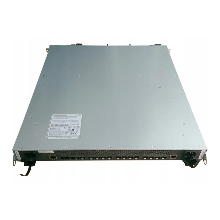
TiMax is housed in a 2 unit high 19” rack mount case. Front panel menu and jog wheel controls
allow the operator to select a show, recall presets, mute inputs and outputs and set group fader
levels.
Jog and press
to navigate
Air outlet
DO NOT BLOCK
Air intake
DO NOT BLOCK
Do not
load
firmware
In addition to soft functions
as indicated on LCD, these
buttons have special functions
during boot up, apply power and
press button to activate
Do not
load
show file
Activate
Bypass
signal path
(option)
Boot from
secondary
disk
PSU & fan
fault LEDs
Rear panel I/O and control ports are shown for a fully loaded 64 x 64 matrix system below.
PSU A
inlet
(standard)
PSU B
inlet
(option)
Bypass
Inputs
(option)
Analogue inputs
8 channels per
connector
(standard)
Analogue outputs
8 channels per
connector
AES inputs
16 channels
(option)
GPIO
port
Ethernet
port
MIDI 1
port
Multi channel
audio transport
port A
(option)
Multi channel
audio transport
port B
(option)
MIDI 2
port
AES outputs
16 channels
(option)
C h an ne l
1-16
C h an ne l
17- 32
C h an ne l
33- 48
C h an ne l
49- 64

7
System Block Diagram

8
Au io Inputs & Outputs
Analogue I/O interface (AIO Car s)
The following is the D-Sub 25-Pin configuration. This pinout is equivalent to
Yamaha/Tascam/Digidesign standard analogue DB25>XLR cables.
Analogue input and output connectors on the TiMax are female and in groups of 8 balanced
circuits. D-Sub line connectors are male for both input and output.
AES3 Digital I/O plus Analogue Output interface (MIO Car s)
Each chassis female D-Sub carries 16 channels of input or output (8 stereo pairs) arranged in
accordance with the analogue pin-out standard. This pinout is equivalent to
Yamaha/Tascam/Digidesign standard analogue DB25>XLR cables.

9
MIO Boar Installation & Configuration
Each Mixed Input Output (MIO) card has 16 channels of AES3 input and 16 channels of AES
output as well as 16 channels of analogue output.
When installing the MIO board, a jumper needs to be placed to select the word clock routing.
There can be one to four MIO boards installed in a TiMax2 unit, stacked in the IO board area. On
the uppermost board, the jumper is installed between the left two of the three posts at the JMP1
location. On all lower boards, the jumper is installed between the right two posts.
MIO inputs pass through in input Sample Rate Converter (SRC) which converts and synchronises
incoming input data to the TiMax internal clock. The SRC capture range includes 44.1KHz,
48KHz and 96KHz.
Each pair of AES outputs can be set to clock to any one of a number of clock sources including
external word clock, internal 48K or 96K or a word clock derived from any one of the inputs on
the same MIO card.
Select input
for Word Clock
synchronisation
Select synch
for each AES
output pair
Click here to
save changes
to TiMax

10
Optional Networke an Multi-channel Au io Interface
Multichannel I/O interfaces available for TiMax include:
Cirrus Logic Cobranet – 2 x CAT 5 transport – 32 channels on each
Digigram Ethersound – 2 x CAT 5 transport – 32 channels on each
Audinate Dante – CAT 5 transport
MADI – 2 x 75 ohm coax or optical – 32 channels on each

11
TiMax II MADI Interface Configuration
The MADI interface is set up through the TiMax software interface, the MADI module can be set
to master or slave and 56 or 64 channel format.
Select Unit from the menu bar and choose Unit Information / Configuration, click on the MADI
tab
Click here
to get MADI
card status
Click here
to set MADI
card status
The status of the MADI card can be seen by clicking on the Update Status button. The MADI card
status report is only updated when the Update Status button is clicked.
LED Assignment:
In addition to the reported MADI status, LEDs on the MADI card will show current status:
D1 (YEL) - Rx audio data from MADI is valid
D2 (RED) - 125 MHz Rx VCO is locked (should always be on, will lock to an internal reference if
there is no valid Rx bitstream to recover a clock from)
D3 (RED) - Power good
D4 (YEL) - ~ 250 msec blink rate, based on the audio clock (power up in slave mode with no
MADI Rx, and it will be running slow since the PLL hasn't ever had a good reference to recover
from!)
D5 (RED) - MADI Rx carrier detect

12
Shows MADI card installed in unit

13
TiMax II Cobranet Interface Configuration
The Cobranet interface is set up through the TiMax software interface, Cobranet supports 32
channels of audio so for a 64 channel transport 2 cards are required
Select Unit from the menu bar and choose Unit Information / Configuration, click on the Cobranet
tab
Set receive
bundles for
Cobranet
inputs
Set transmit
bundles for
Cobranet
outputs
Click here to
save changes
to TiMax

14
Control Inputs & Outputs
Ethernet
TiMax communicates with one or more host computers on a local area network via an Ethernet
connection. The Ethernet port operates at 10 or 100 megabits per second, carrying Internet
Protocol (IP) packets that conform to the UDP protocol. A CAT5 cable is used to connect the
network port on the back of TiMax to a port on a switch, hub or router. It is also possible to
connect TiMax directly to a host computer's Ethernet port using a crossover cable (most Macs
and modern PC computers will work with a standard Ethernet cable). Cables used must be
less than 100 meters in length. Note when using a direct cable connection it may be necessary to
turn wireless networking off on the host computer.
Each TiMax unit has a unique Ethernet MAC (hardware) address programmed into its ROM at the
time of manufacture. The TiMax firmware uses this MAC address with the ARP, DHCP and
ICMP protocols to establish and maintain connections with host computers on the local area
network using IP addresses. The IP address that the TiMax uses may be assigned dynamically by a
DHCP server on the network, or manually by the user. If there is no DHCP server present then
TiMax will auto-assign an IP address. TiMax will respond to a "ping" request on its assigned IP
address.
Manual Network Configuration using fixe IP a resses
There are a number of reasons why you may consider using fixed IP addresses, it is possible that
the control computer is connected to TiMax via a Local Area Network (LAN) which is also used
for internet access or part of a wider intranet facility and for reasons of access control you wish to
limit the visibility of the system to unauthorized wired or wireless access. Using the TiMax front
panel controls scroll and press the jog wheel to select IP Address and the scroll wheel and tab key
to set the designated address for the TiMax unit, eg. 123.123.123.001
The IP address and subnet mask of the control computer will also need to be set in the same range.
For XP/Vista/Win7 this is done in Control Panel/Network Connections
Select the connection type, i.e. wired or wireless, go to the TCP/IP properties and set the address as
per the example below. The Apple Mac Network window offers similar options.
Windows TCP/IP Properties setup screen – Control Panel / Internet Connections

15
BEWARE of the following possible reasons for failure to connect:
- Windows and anti virus Firewall may prevent connection, turn firewalls off for fault diagnosis.
- If your computers’ Wired and Wireless TCP/IP settings are in the same range connection can be
prevented. Disable the one you are not using for fault diagnosis. Always disable Mac Air-port to
ensure stable wired Ethernet connection and operation.
- Failure to connect after changing TCP/IP settings in Windows can sometimes be cured by just
waiting for a few minutes for the new settings to become effective or by restarting the computer.
- Another device on the network has the same address as the control computer.
GPIO Input
TiMax provides a General Purpose Input / Output (GPIO) parallel contact closure interface for
triggering cues and controlling external equipment. The pinout for the GPIO connector (female
DB-25) is provided in the following chart.
All inputs and outputs are opto-isolated for reliable operation in a variety of electrical
environments. There are eight address inputs, two trigger inputs and two outputs. Each of these
inputs and outputs is a two-wire current loop, a signal line and a current return line.
pin GPIO pin GPIO
1 address 0 14 address 0 return
2 address 1 15 address 1 return
3 address 2 16 address 2 return
4 cue trigger 17 cue trigger return
5 address 3 18 address 3 return
6 address 4 19 address 4 return
7 address 5 20 address 5 return
8 address 6 21 address 6 return
9 playback trigger 22 playback trigger return
10 address 7 23 address 7 return
11 output 1 24 output 1 return
12 output 2 25 output 2 return
13 not used
G P I N P U T S
An input can be activated by placing a voltage on the signal line of 5 to 24 volts DC with respect to
the current return line. An input can be deactivated by placing a voltage on the signal line of 0.8
volts DC or less with respect to the current return line, or by opening the current loop. The current
loop has an impedance of approximately 4000 ohms. The trigger inputs are locked out following a
valid trigger, preventing false retriggering due to contact bounce or noise. The default lockout time
is 1 second.
There are two forms of playback GO. A simple GO, sometimes called a null GO, starts playback
on all channels that have audio files already loaded on them. It is very fast <1mS. (If a channel is
already playing audio, that channel is unaffected.)

16
A full GO specifies an audio file and a location to start playback in the file. It can take up to about
20 milliseconds from when the command is received to when playback starts.
The playback GPI trigger does two things: it recalls a preset (numbered 256..511) and at the same
time it does a null playback GO.
The other GPI trigger, the cue trigger, just recalls a preset (numbered 0..255).
When the cue trigger input is activated, the number binary-encoded on the address lines (0..255) is
read, and the cue with that number is activated.
When the playback trigger input is activated the cue at 256 + the number binary-encoded on the
address lines (0..255) and a playback GO is generated on all enabled playback channels which will
start playback within 1 millisecond for pre-loaded.
A show control GO which activates the next cue is also available by setting all zeros on the
address lines and activating a cue trigger.
GPIO Output
To be implemented in future software release.
MIDI
TiMax has two standard MIDI ports on the rear panel. Port 1 is a general-purpose port. Any MIDI-
formatted TiMax command, including standard MIDI continuous-controller commands for control
of Group Faders from generic MIDI faders as well as MIDI Show Control and MIDI system
exclusive commands can be received on the MIDI 1 IN.
In the TiMax2 SoundHub-R version, the Cue List’s Preset/Cue numbers are hard-programmed to
trigger from equivalent MIDI Program Change numbers sent to MIDI IN1 on MIDI Channel 1.
In the S-Version MIDI Note or Program Change triggers can be freely mapped to any values using
the New Cue or Update Cue dialogue (more later).
The second MIDI port is for interfacing to the TiMax Tracker radar-technology performer tracking
system or to a console for remote preset recall.
The tracking system interface sends MIDI controller messages to TiMax to automatically recall
TiMax level/delay Routings when the appropriate MIDI controller signals are sent from a TiMax
Tracker computer (see later and Appendix2)
The remote preset recall mechanism uses MIDI program changes to recall TiMax presets; program
change 1-128 on channel 1 will recall the first 128 presets, program change 1-128 on channel 2
will recall the next 128 presets etc.

17
Front Panel Controls
Group Fa ers & Mute
These are live controls accessible via the front panel of the unit. Press the Menu button, scroll to
Groups and press the jog wheel to select. To select a Group to control, scroll to the desired channel
and press the jog wheel to select, then scroll to alter the level.
The channels controlled by a Group fader are assigned in the PC or Mac control software and may
be freely defined in each show to control any combination of inputs and outputs. So for example
Group 1 could be setup as a grand master controlling all outputs, while others may be assigned to
control sub zones, announcer mics, DJ, Band or stage sources.
Group assignments and levels will be remembered if TiMax is switched off and on again.
Group fader levels may be controlled by physical MIDI faders plugged into the rear panel MIDI 1
input port. After booting up, the unit will respond to an incoming continuous controller message,
as sent by a MIDI fader arriving on any enabled MIDI channel, setting the level for the group that
corresponds to the controller number in the message (controller zero mapped to the first group).
The default is all channels enabled. There is a command in the firmware to enable a specific MIDI
channel; message from other channels are ignored.
Channel Meters & Mute
Signal levels on each input and output can be seen on the front panel LCD, the 16 channel wide
display may be scrolled with the jog wheel and input or output selected by pressing the jog wheel
switch in order to access the Mute and Solo functions .
Note: To mute and un-mute all channels, press and hold the Mute switch.
Select a Show
Use the jog wheel scroll and press to go to and select a show from the list
Select a Preset
Use the jog wheel scroll to a preset from the list. Use the Select button to select that preset and
again to recall the next preset in the list.
IP A ress
Allows setting of fixed or DHCP assigned IP addresses. (See P8.- Ethernet)
Setup & Information
Displays unit information and provides facility to reset the unit to factory default.

18
Get out of Jail Free
In the event of a system crash due to firmware corruption of show file corruption, here are a couple
of things to try…
1.
Reboot the unit while holding down the left button under the LCD display – this will boot
the unit from ROM and will allow the firmware to be re-installed from the PC or Mac.
When the software is launched you will be prompted to load the version of firmware that is
embedded into the control software.
2.
Reboot the unit while holding down the centre button under the LCD display – this will
boot the unit without auto loading the most recent show file. To reinstate the show file
select File/Open Show Online, this will upload the show file from the PC or Mac disk to
the TiMax unit.
3.
Reboot the unit while holding down the right button under the LCD display – this will boot
the unit from the secondary disk (if fitted).

19
High Reliability Options
Dual Mirrore Har Disk Drives
An optional 2
nd
hard disk drive can be fitted into TiMax that mirrors the first disk and in the event
of a hard disk failure takes over.
Dual Power Supply an cooling fan
An optional 2
nd
power supply and cooling fan can be fitted into TiMax for high reliability
applications. The 2
nd
power supply has its own power cord and fuse.
Bypass
An optional analogue Bypass feature can be fitted to TiMax that allows an additional set of 8
analogue inputs to be selectively routed to pre-programmed outputs outside the DSP signal path
allowing for mission critical applications to have a fail safe facility.
The Bypass system does however use analogue buffers so will not pass audio in the event of
total power failure.

20
Software controller
Overview
Versions of the software are available for Mac and PC. Connection to the TiMax may be direct
using a Cat5 cable (some computers may need a cross-over cable) or connected through a switch
or hub using existing network infrastructure or wireless using a wireless access point.
The software is a live control surface for one or more TiMax DSP audio matrix units offering
control of up to 64 channels on each TiMax unit of input EQ, output EQ, level and delay at each
matrix crosspoint as well as sound file playback and sophisticated snapshot and cross-fade
automation.
Windows for Files, Presets/Cues, Routing and EQ Libraries may be hidden or visible and can be
docked either to the left or right of the fader section, or be placed where ever is most useful and
convenient.
Un-docking is achieved by clicking on the button and docking by clicking and dragging the
page to the left or right of the screen and releasing.
For example a computer with multiple screens could have all the pages open and visible. The
Preset/Cue control page is defined as an “always on top” window.
In the example layout below the EQ and Routing library pages are to the right of the faders
section, the EQ library page can be brought to the front by clicking on its the tab at the bottom of
the screen.
This manual suits for next models
1
Table of contents
