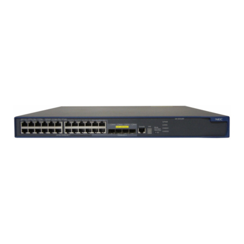
NEC UX5000 User manual

Empowered by Innovation
Gigabit PoE Switch Manual
P/N 0913101
Rev 1, July 2008
Printed in U.S.A.
Technical Support Web Site:
http://www.necux5000.com

This manual has been developed by NEC Unified Solutions, Inc. It is intended for the use of its customers and
service personnel, and should be read in its entirety before attempting to install or program the system. Any
comments or suggestions for improving this manual would be appreciated. Forward your remarks to:
NEC Unified Solutions, Inc.
4 Forest Parkway
Shelton, CT 06484
necunifiedsolutions.com
Nothing contained in this manual shall be deemed to be, and this manual does not constitute, a warranty of, or
representation with respect to, any of the equipment covered. This manual is subject to change without notice and
NEC Unified Solutions, Inc. has no obligation to provide any updates or corrections to this manual. Further, NEC
Unified Solutions, Inc. also reserves the right, without prior notice, to make changes in equipment design or
components as it deems appropriate. No representation is made that this manual is complete or accurate in all
respects and NEC Unified Solutions, Inc. shall not be liable for any errors or omissions. In no event shall NEC Unified
Solutions, Inc. be liable for any incidental or consequential damages in connection with the use of this manual. This
document contains proprietary information that is protected by copyright. All rights are reserved. No part of this
document may be photocopied or reproduced without prior written consent of NEC Unified Solutions, Inc.
©2008 by NEC Unified Solutions, Inc. All Rights Reserved.
Printed in U.S.A.

Gi
g
abit PoE Switch Manual i
___________________________________________________________________________________
___________________________________________________________________________________
T
Ta
ab
bl
le
e
o
of
f
C
Co
on
nt
te
en
nt
ts
s
Chapter 1 Regulatory
Section 1 Safety Notices ..............................................................................1-1
Section 2 Industry Canada (Canada) ..........................................................1-1
Section 3 IC Statement .................................................................................1-2
Section 4 Certification and Compliance .....................................................1-2
4.1 FCC Part 68 Notice ................................................................................ 1-2
Section 5 Industry Canada (IC) Notice ......................................................1-3
Chapter 2 GSWU Blade
Section 1 Description ...................................................................................2-1
Section 2 Indicators, Switches and Connectors .......................................2-2
2.1 LED Indicators ........................................................................................ 2-2
2.2 Connectors ............................................................................................. 2-3
2.3 Switches ................................................................................................. 2-3
2.4 Power and Thermal Considerations ....................................................... 2-3
2.5 Environmental Considerations ............................................................... 2-3

ii Table of Contents
___________________________________________________________________________________
___________________________________________________________________________________
Revision 1 UX5000
Chapter 3 GSWU Blade Setup
Section 1 Installing the GSWU Blade .........................................................3-1
1.1 System Requirements ............................................................................ 3-1
1.2 Installation and Safety Precautions ........................................................ 3-1
1.3 Installing the GSWU Blade in the Chassis ............................................. 3-2
Section 2 UX5000 Programming .................................................................3-2
Chapter 4 GSWU Blade Configuration
Section 1 Configuring the GSWU Blade .....................................................4-1
Section 2 Configuring the PC ......................................................................4-1
Chapter 5 Gigabit PoE Switch Web Manager
Section 1 Logging in to Gigabit PoE Switch (GSWU Blade) ....................5-1
Section 2 Home Menu ..................................................................................5-2
Section 3 Port Link Status ...........................................................................5-4
Section 4 Port Configuration .......................................................................5-5
Section 5 PoE Settings ................................................................................5-7
Section 6 Port Mirroring Configuration ......................................................5-9
Section 7 Port PVID ....................................................................................5-10
Section 8 VLAN Configuration ..................................................................5-11

UX5000 Revision 1
Gigabit PoE Switch Manual iii
___________________________________________________________________________________
___________________________________________________________________________________
Section 9 Firmware Download ..................................................................5-13
Section 10 Session Management ................................................................5-15
Section 11 Initialization ................................................................................5-17
Chapter A Glossary
Section 1 Introduction ................................................................................. A-1
Section 2 Terms and Definitions ............................................................... A-1

iv Table of Contents
___________________________________________________________________________________
___________________________________________________________________________________
Revision 1 UX5000
THIS PAGE INTENTIONALLY LEFT BLANK

Gi
g
abit PoE Switch Manual v
___________________________________________________________________________________
___________________________________________________________________________________
L
Li
is
st
t
o
of
f
F
Fi
ig
gu
ur
re
es
s
a
an
nd
d
T
Ta
ab
bl
le
es
s
Figure 2-1 GSWU Blade ...........................................................................................................2-2
Table 2-1 GSWU Blade Switch Settings ..................................................................................2-3
Figure 3-1 Inserting Blades in the Chassis ...............................................................................3-2
Table 4-1 Network Settings for TCP/IP Addressing .................................................................4-1
Figure 4-1 Selecting Control Panel ...........................................................................................4-2
Figure 4-2 Control Panel Screen ..............................................................................................4-3
Figure 4-3 Network Connections Screen ..................................................................................4-3
Figure 4-4 Local Area Connection Status Screen .....................................................................4-4
Figure 4-5 Local Area Connection Properties Screen ..............................................................4-4
Figure 4-6 Internet Protocol (TCP/IP) Properties Screen .........................................................4-5
Figure 5-1 Login Screen ...........................................................................................................5-1
Figure 5-2 Home Menu .............................................................................................................5-2
Figure 5-3 Port Link Status Screen ...........................................................................................5-4
Figure 5-4 Port Configuration Screen .......................................................................................5-6
Table 5-1 Maximum Power – Blades .......................................................................................5-7
Table 5-2 IEEE802.af Class Specifications .............................................................................5-7
Figure 5-5 PoE Settings Screen ...............................................................................................5-8
Figure 5-6 Port Mirroring Configuration Screen ........................................................................5-9
Figure 5-7 Port PVID Screen ..................................................................................................5-10
Figure 5-8 VLAN Configuration Screen ..................................................................................5-12
Figure 5-9 Firmware Download Screen ..................................................................................5-13
Figure 5-10 Firmware Download Screen ..................................................................................5-14
Figure 5-11 Session Management Screen ...............................................................................5-16
Figure 5-12 Initialization Screen ...............................................................................................5-17
vi List of Figures and Tables
___________________________________________________________________________________
___________________________________________________________________________________
Revision 1 UX5000
THIS PAGE INTENTIONALLY LEFT BLANK

Gi
g
abit PoE Switch Manual 1 - 1
___________________________________________________________________________________
C
Ch
ha
ap
pt
te
er
r
1
1
Regulatory
This product has been tested and complies with the specifications for a Class B digital
device, pursuant to Part 15 of the FCC Rules. These limits are designed to provide
reasonable protection against harmful interference in a residential installation.
This equipment generates, uses, and can radiate radio frequency energy and, if not
installed and used according to the instructions, may cause harmful interference to
radio communications.
There is no guarantee that interference will not occur in a particular installation. If this
equipment causes harmful interference to radio or television reception, which is found
by turning the equipment off and on, the user is encouraged to try to correct the
interference by one or more of the following measures:
❑
Reorient or relocate the receiving antenna.
❑
Increase the separation between the equipment or devices.
❑
Connect the equipment to an outlet other than the outlet for the receiver.
❑
Consult a dealer or an experienced radio/TV technician for assistance
S
ECTION
1S
AFETY
N
OTICES
S
ECTION
2I
NDUSTRY
C
ANADA
(C
ANADA
)
This device complies with Industry Canada ICES-003 rule. Cet appareil est conforme
à la norme NMB003 d'Industrie Canada.
To reduce the risk of fire, use only No.26 AWG or larger
telecommunication line cord. Do not use this product near water,
for example, in a wet basement or near a swimming pool. Avoid
using this product during an electrical storm. There may be a
remote risk of electric shock from lightning.

1 - 2 Regulatory
___________________________________________________________________________________
___________________________________________________________________________________
Revision 1 UX5000
S
ECTION
3 IC S
TATEMENT
Operation is subject to the following conditions:
1. This device may not cause interference.
2. This device must accept any interference, including interference that may cause
undesired operation of the device.
S
ECTION
4C
ERTIFICATION
AND
C
OMPLIANCE
4.1 FCC Part 68 Notice
This equipment complies with Part 68 of the FCC Rules and the requirements
adopted by ACTA. On the bottom surface of this equipment is a label that
contains, among other information, a product identifier in the format
US:AAAEQ##TXXXX. If requested, this number must be provided to the
telephone company.
This equipment uses RJ48C and R11 jacks.
A plug and jack used to connect this equipment to the premises wiring and
telephone network must comply with the applicable FCC Part 68 rules and
requirements adopted by ACTA. See installation instructions for details.
If this equipment, the Gigabit Switch causes harm to the telephone network,
the telephone company will notify you in advance that temporary
discontinuance of service may be required. But if advance notice is not
practical, the telephone company will notify the customer as soon as possible.
Also, you will be advised of your right to file a complaint with the FCC if you
believe it is necessary.
The telephone company may make changes in its facilities, equipment,
operations or procedures that could affect the operation of the equipment. If
this happens, the telephone company will provide advance notice in order for
you to make the necessary modifications to maintain uninterrupted service.
If the equipment is causing harm to the telephone network, the telephone
company may request that you disconnect the equipment until the problem is
resolved.
This equipment contains no user-serviceable parts.

UX5000 Revision 1
Gigabit PoE Switch Manual 1 - 3
___________________________________________________________________________________
___________________________________________________________________________________
S
ECTION
5I
NDUSTRY
C
ANADA
(IC) N
OTICE
This equipment meets the applicable Industry Canada Terminal Equipment Technical
Specifications. This is confirmed by the registration number. The abbreviation, IC,
before the registration number signifies that registration was performed based on a
Declaration of Conformity indicating that Industry Canada technical specifications
were met. It does not imply that Industry Canada approved the equipment.
Before installing this equipment, users should ensure that it is permissible to be
connected to the facilities of the local telecommunications company. The equipment
must also be installed using an acceptable method of connection. The customer
should be aware that compliance with the above conditions may not prevent
degradation of service in some situations.
Repairs to certified equipment should be coordinated by a representative designated
by the supplier. Any repairs or alterations made by a user to this equipment, or
equipment malfunctions, may give the telephone communications company cause to
request the user to disconnect the equipment.
Users should ensure for their own protection, that the electrical ground connections of
the power utility, telephone lines and internal metallic water pipe system, if present,
are connected together. This precaution may be particularly important in rural areas”.
Users should not attempt to make such connections themselves,
but should contact the appropriate electric inspection authority,
or electrician, as appropriate.

1 - 4 Regulatory
___________________________________________________________________________________
___________________________________________________________________________________
Revision 1 UX5000
-- NOTES --

Gi
g
abit PoE Switch Manual 2 - 1
___________________________________________________________________________________
C
Ch
ha
ap
pt
te
er
r
2
2
GSWU Blade
S
ECTION
1D
ESCRIPTION
The GSWU blade is a managed 8-port Gigabit PoE Switch. The Gigabit PoE Switch
provides offices that require high network performance to exchange large data files
and images and access real-time information or connect to high-speed servers or a
high-speed network backbone.
Using Auto-MDI/MID-X, the fastest connection speed is automatically detected. The
ports automatically adjust to the speed of network devices communicating at 1000,
100, or 10 Mbps, so the switch can accommodate a range of workgroup applications.
This blade provides:
❑
Ethernet Ports:
❍
8 Gigabit Ethernet (10/100/1000) user ports
❍
Status LEDs Indicating Link, Speed and Activity
❍
User ports source PoE based on the 802.3af standard
❍
Auto-MDI/MDI-X Auto – automatically detects and corrects crossover cables
❑
Basis Layer 2 Switch Management:
❍
802.1Q (VLAN Bridging)
❍
Independent VLAN Learning Support
❍
802.1p Priority Queuing
❍
Port Mirroring
❍
802.3x Flow Control
❑
Blade Management:
❍
Dynamic PoE Control – allows setting proper PoE classifications for each port in
order to stay within the system power budget
❑
Management Interfaces:
❍
Provides a Web-Base Utility for remote management and upgrades

2 - 2 GSWU Blade
___________________________________________________________________________________
___________________________________________________________________________________
Revision 1 UX5000
S
ECTION
2I
NDICATORS
, S
WITCHES
AND
C
ONNECTORS
Refer to Figure 2-1 GSWU Blade for LED and switch locations.
2.1 LED Indicators
The LEDs for each port indicate of the status of an activity.
Figure 2-1 GSWU Blade
RJ45
Connector
(x8)
Activity LED
(x8)
LED Display Port Status
Solid Green 1000 Mbps Link
Solid Yellow 10/100 Mbps Link
Off No Link
Blinking LED Port Activity

UX5000 Revision 1
Gigabit PoE Switch Manual 2 - 3
___________________________________________________________________________________
___________________________________________________________________________________
2.2 Connectors
The following connectors are used:
❍
J1 (Backplane Connector)
This connector is used to connect to the CCPU blade or other
blades in the chassis.
❍
J5 (Ethernet Ports)
There are eight ports for 10/100/1000 Mbps Ethernet
connectivity. Ports are auto-sensing for speed, duplexing,
polarity and MDI-X.
2.3 Switches
SW2 is located on the GSWU blade. Table 2-1 GSWU Blade Switch Settings
shows the switches and their settings. Note that SW2-3 is the only setting that
should be changed on this blade. SW2-3 can be changed from On to Off to
reset the blade to the factory defaults.
2.4 Power and Thermal Considerations
The GSWU blade draws about 6W of power from the 3.3 VDC supply. For
PoE, the maximum power draw is 123W from the 48 VDC rail, if all ports are
set to Class 3.
Dynamic PoE configuration is used to prevent overloading the 48 VDC supply,
which has a limit of 96W.
2.5 Environmental Considerations
The following environmental conditions apply to the GSWU blade:
Operating Temperature: +32˚F ~ +104˚F (0˚C ~ 40˚C)
Recommended Long Term Temperature: -4˚F ~ +140˚F (-20˚C ~ 60˚C)
Operating Humidity: 10 ~ 90% RH (non-condensing)
Recommended Long Term Humidity: 10 ~ 90% RH
Table 2-1 GSWU Blade Switch Settings
Switch
SW2 Default Switch Setting/Description
1 Off – Not Used
2 Off – Not Used
3 Off – Set to On to reset the blade to factory default settings
4 Off – Not Used

2 - 4 GSWU Blade
___________________________________________________________________________________
___________________________________________________________________________________
Revision 1 UX5000
-- NOTES --

Gi
g
abit PoE Switch Manual 3 - 1
___________________________________________________________________________________
C
Ch
ha
ap
pt
te
er
r
3
3GSWU Blade Setup
SECTION 1INSTALLING THE GSWU BLADE
1.1 System Requirements
This blade can be installed in any universal slot in the controlling chassis
(slots 2~6) and expansion chassis (slots 7~24).
1.2 Installation and Safety Precautions
Never install telephone wiring during a lightning storm.
Never install telephone jacks in wet locations unless the jack is
specifically designed for wet locations.
Never touch uninsulated telephone wires or terminals unless the
telephone line is disconnected at the network interface.
Use caution when installing or modifying telephone lines.
Ground the Controlling and Expansion chassis before installing or
removing the blades.
The Expansion Chassis must be installed with the system power
OFF.
Do not touch the blade components.
Carry the blade in a conductive polyethylene bag to prevent static
electricity until ready to install the blade.
When installing or removing the blades from the chassis, the installer
must wear a grounded wrist strap to protect the blade from static
electricity.
This blade is hot-swappable.
Observe the following precautions when installing the
blades to avoid static electricity damage to hardware or
exposure to hazardous voltages.

3 - 2 GSWU Blade Setup
___________________________________________________________________________________
___________________________________________________________________________________
Revision 1 UX5000
1.3 Installing the GSWU Blade in the Chassis
To install an this blade with the system running:
1. Insert the blade within the guide rail and push the blade securely into
position. Tighten the thumb screws on either side of the blade.
SECTION 2 UX5000 PROGRAMMING
The GSWU blade can be programmed using a Multiline Terminal, PCPro or WebPro.
1. To program the system, the GSWU blade should be installed in the desired
universal slot.
2. Access Programming press: Speaker #* # * [system password] HOLD.
Figure 3-1 Inserting Blades in the Chassis
Password User
Name Level Programs at this Level
12345678 tech 2 (IN) Installation (IN):
All programs in this section not listed below for SA and SB
0000 ADMIN1 3
(SA)
System Administrator – Level 1 (SA):
10-01, 10-02, 10-12, 10-13, 10-14, 10-15, 10-16, 10-17,
10-18, 10-22, 12-02, 12-03, 12-04, 15-01, 15-07, 15-09,
15-10, 15-11, 20-16, 21-07, 21-14, 22-04, 22-11, 25-08, 30-
03, 32-02, 40-02, 41-02, 41-03, 41-04, 41-05, 41-06, 41-
07, 41-08, 41-09, 41-10, 41-11, 41-12, 41-13, 41-14, 41-15,
41-16, 41-17, 41-18, 90-03, 90-04, 90-06, 90-07, 90-18,
90-19
9999 ADMIN2 4
(SB)
System Administrator – Level 2 (SB):
13-04, 13-05, 13-06

UX5000 Revision 1
Gigabit PoE Switch Manual 3 - 3
___________________________________________________________________________________
___________________________________________________________________________________
3. Access PRG 10-55: Blade Network Setup to set the network information for
the GSWU blade.
❑10-55-01 IP Address
❑10-55-03 Main/Add-on
❑10-55-04 Sub Net Mask
❑10-55-05 Default Gateway
4. To exit terminal programming, press MIC to exit out of any displayed programs +
Speaker.
This program option is very important. When the
GSWU blade is utilized, it obtains its Networking
information according to the settings in data
programs 10-55-01~10-55-05. When Main is selected
in 10-55-03, the blade will obtain its networking
configured in 10-55.

3 - 4 GSWU Blade Setup
___________________________________________________________________________________
___________________________________________________________________________________
Revision 1 UX5000
-- NOTES --
Other manuals for UX5000
17
Table of contents
Other NEC Switch manuals

NEC
NEC SMB8000 User manual

NEC
NEC NEC Express5800 Series User manual

NEC
NEC N8406-023 Operating manual

NEC
NEC mPD98410 User manual

NEC
NEC SA3500G User manual

NEC
NEC N8191-09 User manual

NEC
NEC USB User manual

NEC
NEC IntelliBase A3844 User manual

NEC
NEC NEC Express5800 Series User manual

NEC
NEC MM2000 User manual
Popular Switch manuals by other brands

PCB Piezotronics
PCB Piezotronics IMI SENSORS EX686B11 Installation and operating manual

SMC Networks
SMC Networks D-M9NAV Installation & maintenance manual

S&C
S&C 6801M instruction sheet

NOSHOK
NOSHOK 800 Series operating instructions

Splash
Splash Bootloader Domestic Installation

3Com
3Com SuperStack II 3900 Getting started guide