manuals.online logo
Brands
  1. Home
  2. •
  3. Brands
  4. •
  5. Zamel
  6. •
  7. Measuring Instrument
  8. •
  9. Zamel Exta LKM-03 User manual

Zamel Exta LKM-03 User manual

POWER SUPPLY INDICATOR LKM-03 INSTRUCTION MANUAL
Zakład Mechaniki i Elektroniki
ZAMEL sp.j.
J.W. Dzida, K. Łodzińska
ul. Zielona 27, 43-200 Pszczyna, Poland
Tel. +48 (32) 210 46 65, Fax +48 (32) 210 80 04
www.zamelcet.com, e-mail: [email protected]
VER. 001_20.01.2010
FEATURES
TECHNICAL DATA
DESCRIPTION
APPERANCE
● Single-phase voltage presence
optical signalling,
● High-brightness LED applied,
● High durability optical indicator
applied,
● Various LED colours available,
● Easy applicable together with atypi-
cal systems,
● monomodular casing,
● TH-35 DIN rail installation.
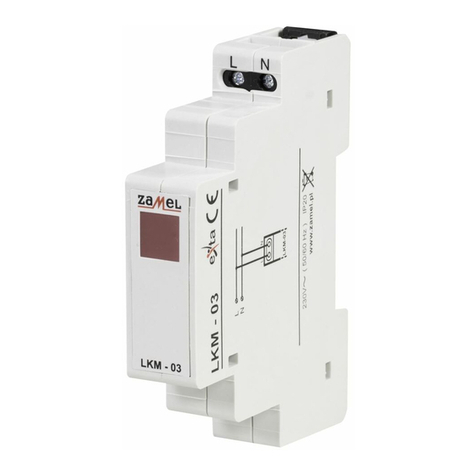
The LKM-03 power supply indicator is
designed for single-phase system volt-
age signalling. Voltage presence is being
signalled by means of a high-brightness
LED. Various LED colour versions are
available (red, green, yellow).
The device is designed for
three-phase installation and
must be installed in accor-
dance with standards valid
in a particular country. The
device should be connec-
ted according to the details
included in this operating manual. Installa-
tion, connection and control should be car-
ried out by a qualied electrician st aff, who
act in accordance with the service manual
and the device functions. Disassembling
of th e devi ce i s equ al wi th a loss o f guaran -
tee and can cause electric shock. Before
installation make sure the connection
cables are not under voltage. The cruci-
form head screwdriver 3,5 mm should be
used to instal the device. Improper trans-
port, storage, and use of the device inu-
ence its wrong functioning. It is not advi-
sable to instal the device in the following
cases: if any device part is missing or the
device is damaged or deformed. In case
of improper functioning of the device con-
tact the producer.
CAUTION
LKM-03
Power terminals: L, N
Rated voltage: 230 V~
Rated voltage tolerance: -15 ÷ +10 %
Rated frequency: 50 / 60 Hz
Rated current for 10/20/30 versions: 3,5 mA / 15 mA / 15 mA
Power supply indicator: LED
Number of terminal clamps: 2
Section of connecting cables: 0,2 ÷ 2,5 mm2
Ambient temperature range: -20 ÷ +45 oC
Operating position: freely
Mounting: rail TH 35 (PN-EN 60715)
Protection degree: IP20 (PN-EN 60529)
Protection level: II
Overvoltage category: II
Pollution degree: 2
Dimensions: monomodular (17,5 mm) 90x17,5x66 mm
Weight: 45 g
Reference standards: PN-EN 60947-5-1
Power terminal (N)
Power terminal (L)
Voltage indicator
The symbol means selective
collecting of electrical and electronical
equipment. It is forbidden to put
the used equipment together
with other waste
VER. 001_20.01.2010
MOUNTING, FUNCTIONING
APPLICATION
TIME DIAGRAMS
PRODUCT FAMILY
LKM-03 power supply indicator belongs
to LKM voltage indicators family.
1. Disconnect the power supply from
the mains by the phase fuse, the
circuit-breaker or the switch-di-
sconnector that are joined to the
proper circuit,
2. Check if there is no voltage on
connection cables by means of
a special measure equipment,
3. Install LKM-03 device in the
switchboard on TH-35 DIN rail,
4. Connect the cables with the ter-
minals according to installing dia-
gram,
5. Switch on the power supply from
the mains.
The device is ready to work just
right after its appropriate connec-
ting. The LED indicator signals vol-
tage presence of the selected phase
wire. In case of the voltage lack LED
does not light.
CONNECTING
DIMENSIONS
INNER DIAGRAM
The LKM-03 power supply indicator
signals single-phase voltage presence.
Device version:
01 - three-phase power supply with neutral
wire N
02 - three-phase power supply without
neutral wire N
03 - single-phase power supply with neutral
wire N, high brightness LED
04 - three-phase power supply with neutral
wire N, high brightness LEDs
05 - three-phase power supply with neutral
wire N, high brightness LEDs
Colour version:
10 - red LED (not applied to LKM-04,
LKM-05)
20 - green LED (not applied to LKM-04,
LKM-05)
30 - yellow LED (not applied to LKM-04,
LKM-05)
40 - LED yellow, green, red (not applied
to LKM-03)
Device symbol
WARRANTY CARD
Salesman stamp and signature, date of sale
There is 24 months guarantee on the product
1. ZMIE ZAMEL SP. J. assures 24 months guarantee for the product.
2. The manufacturer’s guarantee does not cover any of the following actions:
a) mechanical damage during transport, loading / unloading or under other circumstances,
b) damage caused by incorrect product mounting or misuse,
c) damage caused by unauthorised modications made by the PURCHASER or any third parties to the product or any other devices
needed for the product functioning,
d) damage caused by Act of God or any other incidents independent of the manufacturer.
3. The PURCHASER shall lay any claims in writing to the dealer or ZMIE ZAMEL SP. J.
4. ZMIE ZAMEL SP. J. is liable for processing any claim according to current Polish legislation.
5. ZMIE ZAMEL SP. J. shall process the claim at its own discretion: product repair, replacement or money return.
6. The manufacturer’s guarantee is valid in the Republic of Poland.
7. The PURCHASER’s statutory rights in any applicable legislation whether against the retailer arising from the purchase contract or
otherwise are not affected by this warranty.

Other Zamel Measuring Instrument manuals

Zamel LKM - 01 User manual

Zamel

Zamel LKM - 01 User manual

Zamel exta LKM-02 User manual

Zamel

Zamel exta LKM-02 User manual

Zamel exta LEM-40 User manual

Zamel

Zamel exta LEM-40 User manual

Zamel LKM - 01 User manual

Zamel

Zamel LKM - 01 User manual

Zamel EXTA LDM-10 User manual

Zamel

Zamel EXTA LDM-10 User manual

Zamel LKM-03 User manual

Zamel

Zamel LKM-03 User manual

Zamel LEM-30 User manual

Zamel

Zamel LEM-30 User manual

Zamel exta LEM-04 User manual

Zamel

Zamel exta LEM-04 User manual

Popular Measuring Instrument manuals by other brands

Alemite 3679 Service guide

Alemite

Alemite 3679 Service guide

Test Equipment Depot 89088 instruction manual

Test Equipment Depot

Test Equipment Depot 89088 instruction manual

Silex technology WM-100 How to use

Silex technology

Silex technology WM-100 How to use

Panametrics DigitalFlow GC868 Startup guide

Panametrics

Panametrics DigitalFlow GC868 Startup guide

Nikon DTM-502 Series instruction manual

Nikon

Nikon DTM-502 Series instruction manual

Essilor EYE-RULER 2 installation manual

Essilor

Essilor EYE-RULER 2 installation manual

Kobold ZOE-ZB**FB series operating manual

Kobold

Kobold ZOE-ZB**FB series operating manual

KROHNE GA24 Supplementary instructions

KROHNE

KROHNE GA24 Supplementary instructions

HCI Tire-Safeguard TPM-V installation manual

HCI

HCI Tire-Safeguard TPM-V installation manual

Niigata seiki VHS-30D instruction manual

Niigata seiki

Niigata seiki VHS-30D instruction manual

SKC NoiseCHEK operating instructions

SKC

SKC NoiseCHEK operating instructions

Martindale Electric CM58 instruction manual

Martindale Electric

Martindale Electric CM58 instruction manual

FAN LactoFAN2 Instructions for use

FAN

FAN LactoFAN2 Instructions for use

Servomex SERVOFLEX MiniMP Operator's manual

Servomex

Servomex SERVOFLEX MiniMP Operator's manual

FLIR MR55 quick start

FLIR

FLIR MR55 quick start

Chino IR-HA Series instructions

Chino

Chino IR-HA Series instructions

Altronics PH-01 quick start guide

Altronics

Altronics PH-01 quick start guide

Siemens 9200 Installation & operation guide

Siemens

Siemens 9200 Installation & operation guide

manuals.online logo
manuals.online logoBrands
  • About & Mission
  • Contact us
  • Privacy Policy
  • Terms and Conditions

Copyright 2025 Manuals.Online. All Rights Reserved.