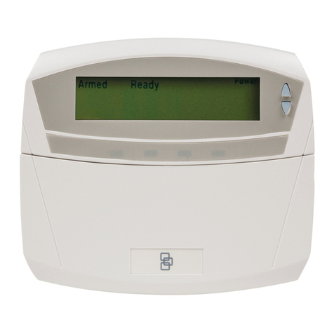
TimeIPS IPS125T User manual

IPS125T
TimeIPS Network Clock and Keypad
Installation Guide
including instructions for
IPS125T- Touch and IPS125T-O Optical
iometric Fingerprint Reader Options

FCC Declaration of Conformity (DoC)
Compliance Information (according to FCC 2.1077)
(1) Product: IPS125T, KEY-PAD18.
The above dev ces comply w th Part 15 of the FCC Rules.
Operat on s subject to the follow ng cond t ons: (1) these dev ces may not cause
harmful nterference and (2) these dev ces must accept any nterference
rece ved, nclud ng nterference that may cause undes red operat on.
(2) The respons ble party s T meIPS, Inc. 5445 E 85th St N, Valley Center KS,
67147. Phone 316.264.1600
Notice to Users
The components n th s system have been tested and found to comply w th the l m ts
for a Class B d g tal dev ce, pursuant to Part 15 of the FCC Rules. These l m ts are
des gned to prov de reasonable protect on aga nst harmful nterference n a
res dent al nstallat on. The dev ces generate, use and can rad ate rad o frequency
energy and, f not nstalled and used n accordance w th the nstruct ons, may cause
harmful nterference to rad o commun cat ons. However, there s no guarantee that
nterference w ll not occur n a part cular nstallat on. If th s equ pment does cause
harmful nterference to rad o or telev s on recept on, wh ch can be determ ned by
turn ng the equ pment off and on, try to correct the nterference by one or more of the
follow ng measures:
•Reor ent or relocate the rece v ng antenna.
•Increase the separat on between the equ pment and rece ver.
•Connect the equ pment nto an outlet c rcu t other than the one to wh ch the
rece ver s connected.
•Consult the dealer or an exper enced rad o/TV techn c an for help.
These dev ces have been tested to comply w th the l m ts for a Class B comput ng
dev ce, pursuant to FCC rules. In order to ma nta n compl ance w th FCC
regulat ons, sh elded cables must be used w th the equ pment f not connected
d rectly to the system. Operat on w th unsh elded cables s l kely to result n
nterference to rad o and telev s on recept on.
CAU ION: Changes and modifications made to the device without the approval
of the manufacturer could void the user's authority to operate this device.
Page 2 http://support.timeips.com 316.264.1600 TimeIPS

able of Contents
IPS125T Series Overview...........................................................................................3
Prepare and Plan....................................................................................................4
Power and attery ackup....................................................................................4
Layout and Installation Considerations.................................................................5
Mounting and Connecting the TimeIPS IPS125T ......................................................6
Mounting and Connecting the Keypad........................................................................7
Initial Configuration of the IPS125T..........................................................................8
Setting a Remote Master IP Address...........................................................................8
Network Troubleshooting............................................................................................9
Accessing System Menu...........................................................................................10
Additional Network Settings.....................................................................................11
IPS125T- iometrics Mounting..............................................................................12
Configure adge Numbers........................................................................................13
Adjusting the Volume and Contrast...........................................................................13
Train Employees and Keypad Commands................................................................14
IPS125T- /O iometrics Training............................................................................15
Technical Support......................................................................................................16
System Specifications...............................................................................................16
IPS125T Series Overview
The TimeIPS IPS125T is a Network Time Clock that connects via an Ethernet
network to a TimeIPS Server ("master") system. The IPS125T- and IPS125T-O
options include a biometric sensor for employee verification when clocking:
IPS125T: No biometric sensor. IPS125T- , IPS125T-O: iometric sensor installed
The included keypad provides:
●PIN number employee clocking and status check
●Job Codes (on TimeIPS systems with job tracking)
●Numeric Clock Notes
●Access to system menu
TimeIPS http://support.timeips.com 316.264.1600 Page 3

Prepare and Plan
The TimeIPS network time clocks are designed to be connected on a LAN (Local
Area Network) or at remote locations on a WAN (Wide Area Network). For WAN,
a secure VPN (Virtual Private Network) is recommended, but a connection can be
made over a standard Internet connection.
We recommend a TimeIPS clock at each employee entrance to your facility and/or
in your central break-room.
Please examine the diagram on the next page to assist in planning your TimeIPS
installation. Most installations will have the first clock at the main employee
entrance. Additional clocks can be added at any time to other entrances or any
location within your business.
Power and Battery Backup
Power for the IPS125T is normally supplied by the included AC power adapter. If
AC power is not available at a convenient location, consider our PoE (Power over
Ethernet) module. The optional PoE module allows a PoE network switch or PoE
injector to provide power to the network clock over the network cable.
In the case of a power outage, you may want to keep the IPS125T powered for a
period of time to allow employees to continue clocking:
When using the AC power adapter:
1. Plug the AC power adapter into a UPS (Un-interruptible Power Supply), or
2. Use the optional AT-36 battery pack. When the AT-36 battery is
connected, the IPS125T can operate for 30 to 80 minutes without power.
The AT-36 will automatically recharge using power supplied by the AC
power adapter in approximately 24 hours.
When using the PoE power adapter:
1. Plug the PoE switch or power injector into a UPS (Un-interruptible Power
Supply), or
2. Use the optional AT-36 battery pack. When the AT-36 battery is
connected, the IPS125T can operate for 30 to 80 minutes without power.
The AT-36 will automatically recharge using power supplied by the PoE
adapter in approximately 24 hours.
Page 4 http://support.timeips.com 316.264.1600 TimeIPS

Layout and Installation Considerations
TimeIPS http://support.timeips.com 316.264.1600 Page 5
!
"#
$
Failure to mount and maintain the IPS125T unit as directed may void the warranty:
●Mount the unit in a dry, indoor location with controlled temperature and humidity. Do
NOT use the unit in any location where rapid temperature changes may cause
condensation. The rated operating temperature is between 0C and 33C (32F to 90F).
●Do not store or use the device in a location that would expose the unit to direct sunlight.
Prolonged exposure to sunlight may cause overheating and/or other damage.
●The unit will become warm during normal use. This does NOT indicate malfunction.
●Mount the device away from strong magnetic or electromagnetic fields, such as those
produced by microwave ovens, two-way radios, or industrial equipment.
Possible Primary and Remote Facility Installation
Existing Ethernet
10/100 Network
Existing Ethernet
10/100 Network
Primary
Facility
Administration
and
Reporting
(Password
Protected)
Side Door
Front Door
Back Door
Remote
Facility
Typical Door Area Installation
TimeIPS Network
Clocks
Any PC with a web
browser
Permanent network
connection
Permanent or
temporary network
connection
%
&'

Mountin and Connectin the TimeIPS IPS125T
A mounting template has been provided for your convenience. A detailed mounting
guide with templates for the IPS125T is also available in the downloads section of
http://support.timeips.com. In most cases, the IPS125T can simply be mounted
with two #6 flat head screws using the wall mounting tabs. For a stronger, tamper-
resistant mounting, attach the metal plate to the wall, and secure with hex screws.
Only use the supplied 5VDC (Positive Center) power adapter or optional TimeIPS
PoE (Power Over Ethernet) adapter. Connecting any other adapter or power supply
may damage the IPS125T and will void the warranty.
Connect employee identification device(s) to the US ports. Connect the network.
Page 6 http://support.timeips.com 316.264.1600 TimeIPS
attery ackup
Connector. Only
connect a TimeIPS
AT-36 battery pack
US Ports for
employee
identification
devices
Power
Connector.
5VDC Positive
Center.
Network Port
10/100 Ethernet
Auxiliary port. This
port is used for special
TimeIPS devices. Do
NOT connect anything
else to this port.
Mount with hang tabs
Mount with Metal Plate
Mounting
Plate Slot

Mountin and Connectin the Keypad
A mounting template has been provided for your convenience. A detailed mounting
guide for the IPS125T is also available in the downloads section of
http://support.timeips.com.
We recommend mounting the keypad with two #6 pan head screws and wall
anchors. Optionally, for rough environments, you may use four screws and wall
anchors. For walls that can not support screws, hook-and-loop fasteners, such as
Velcro brand adhesives, can be used.
The cable routing on the back of the keypad allows the keypad to be mounted
above, below or to either side of your TimeIPS IPS125T Network Clock.
Connect the US cable to a free US port on the back of the Network Clock.
If needed, a US extension or US hub can be used to extend the cable length.
Never use an extension cable if the total cable length will exceed 10 feet. (US HID
devices are limited to 3M cable length.)
Note that it takes 10-15 seconds before the keypad will respond if plugged into a
running TimeIPS system. There is no need to shutdown the system to attach or
detach the keypad.
TimeIPS http://support.timeips.com 316.264.1600 Page 7

Initial Confi uration of the IPS125T
The clock will continue the start-up process for about another 30-60 seconds. When
the start-up process is complete you should see a screen similar to this:
Your new clock must connect to a master station in order to allow your employees
to clock in and out. Using your keypad (or a US keyboard if you do not have a
keypad) select Search for Master and press Enter. The screen on your IPS125T
should flash “Starting System” for a few seconds. You should then see a screen that
looks similar to this:
Settin a Remote Master IP Address
If your IPS125T returned to the “Clock Not Set Up” screen, it was unable to
connect to your master station. If your master station is outside of your local
network, you will need to specify the IP address of that master. Select “Configure
Network” and press Enter. Scroll down to “Set Master IP” and press Enter. You
should see a screen similar to this:
Page 8 http://support.timeips.com 316.264.1600 TimeIPS
After the employee identification device(s) and network cable are attached, power-
on the clock by plugging in the power adapter. In 10-15 seconds you should see
“Starting System” on the LCD. (If not, unplug for 2-3 seconds and try again.)
Step 2) Network Connection Verification
-Clock Not Set Up-
->Search For Master
Configure Network
Clean Shutdown
Step 1) Setting Up the IPS125T
Oct 03, 12:00:00PM
+: In -: Out
/: Check Status
or enter your ID
Oct 03, 12:00:00PM
NETWORK SETUP
Enter Master
(((
)* +
(,
(+
#'-.-(
*( +&.
(*/+
*++0 (
(*&* *
(*(,,((,
,+

Enter the IP address of your master station and press Enter. After a few seconds you
should return to the “Configure Network” menu. TimeIPS will attempt to connect
to the provided IP address of your master station. This may take a few moments. If
your IPS125T was successful in reaching your master station you should see a
screen similar to this:
Network Troubleshootin
In the event that your clock is still unable to reach your master you may need to use
a static IP address (if so, go to page 11), or you may be having network problems.
The first step is to verify your clock has received an IP address from your network.
1) Your clock is set to automatically obtain an IP address from your network via
DHCP by default. To see the IP address of your TimeIPS IPS125T, use the arrow
keys on your keypad to scroll down to “Configure Network” and press Enter.
TimeIPS should display a screen similar to the following:
Select “Show Network Info” and press Enter to see the IP address of your TimeIPS
clock. You should see something like this:
2) If no network connection was detected you should see the following screen:
If you see this screen, check the network cable on the back of the TimeIPS unit.
Unplug and reconnect the network cable at both ends and/or try a different network
cable. The green link light should be on. If not, your network is not working.
Once you have checked the cable and/or reconnected it, scroll down to “Revert to
DHCP” and press Enter. When you return to the “Configure Network” menu, scroll
down to “Apply Settings” and press Enter. This will cause TimeIPS to rescan your
network for an IP address. Repeat step 1 above to check the IP address TimeIPS has
received. If TimeIPS is still unsuccessful in obtaining an IP address, please contact
our Technical Support department for further assistance.
TimeIPS http://support.timeips.com 316.264.1600 Page 9
->Show Network Info
Set Master IP
Revert to DHCP
Set IP Address
Ver: 5.2.15
IP: 192.168.1.106
GW: 192.168.1.1
Mst:
( (
&1%
2,(3+
4 %
2,(3+
Ver: 5.2.15
IP: 127.0.0.1
GW:
Mst:
Oct 03, 12:00:00PM
+: In -: Out
/: Check Status
or enter your ID
(((
)* +

Accessin System Menu
If you need to access the menu on your clock you will need to press Enter on your
keypad. To prevent tampering, you can configure the clock to require a badge
number and PIN for access. Initially, no badge number or PIN is needed.
If a badge number and PIN are provided, you will see the User Menu. From here,
the System Menu can be accessed through the System Admin menu item. Users
with administrative access will see a full system menu while those without
administrative access will see a limited system menu.
On your master station you can set “Security and Validation Options” per clock via
the “Clock Configuration” page. These settings are independent of any employee
badge or PIN numbers. Pressing the S key at any time will take you up one level
in the menu system.
Page 10 http://support.timeips.com 316.264.1600 TimeIPS
Full System Menu
Start Screen
Press Enter
Press Enter
(Only f clock s
not conf gured to
requ re a badge
and PIN number)
Enter your
badge
Enter your PIN
Limited System Menu
User Menu
Select System Adm n
Oct 03, 12:00:00PM
+: In -: Out
/: Check Status
or enter your ID
Oct 03, 12:00:00PM
System Menu
Enter Badge Number
Oct 03, 12:00:00PM
System Menu
Enter PIN Number
Check Status
View Benefits
Request Benefits
->System Admin
->Update Settings
Play Test Sound
View System Info
Remote Service
->Update Settings
Configure Network
Play Test Sound
Use Biometrics

Additional Network Settin s
If needed, the TimeIPS IPS125T can be assigned a static IP address on your
network. You may set a static IP address using the menus, or, if it has a DHCP
address and you want to change to static, you can use the web interface provided by
the IPS125T.
(A) If your clock has a DHCP address, but you want to change it to a static address,
the first option is to use the web interface of the clock. To do this, enter the IP
address of the clock into the web browser of any computer on your network:
http://192.168.1.106/
Your web browser will take you to a page where you can set the IP address, Subnet
Mask, Default Gateway, Primary and Secondary DNS servers and the NTP server
for this clock. e sure to click on “Apply Changes” to store your settings.
(B) To set a static IP address through the clock menu you must be an administrative
user. Access the menu and navigate to the Full System Menu. Scroll down to
“Configure Network” and press Enter. Then scroll to “Set IP Address” and press
Enter. You should then see a screen similar to the following:
Specify the IP address you want this clock to have and press Enter. You will see a
screen similar to this:
In a few seconds you will return to the “Configure Network” screen. You do not
need to actually select “Apply Settings” until you have changed all of the network
settings. This usually includes the IP address, Subnet Mask, Gateway and Primary
DNS server.
TimeIPS http://support.timeips.com 316.264.1600 Page 11
Oct 03, 12:00:00PM
NETWORK SETUP
Enter IP Address
$ (
, +
Setting a Static IP Address
Select
“Apply Settings”
to apply network
changes.

Repeat this process to set additional network parameters, such as your Subnet Mask,
Gateway, Primary DNS server and Secondary DNS server. You may also specify
your NTP server if you know its IP address. If you know your NTP server by its
name (such as ntp.yourcompany.com) you will need to use a US keyboard or enter
this information through the web interface. e sure to select “Apply Settings” to
save your changes.
If you have set your clock to a static IP address you can easily change it back to
DHCP. You will need to be an administrative user. Access the menu and navigate
to “Configure Network.” Scroll down to “Revert to DHCP” and press Enter.
You will need to select “Apply Settings.” In some cases, you may need to perform a
full restart or power cycle for the change to take effect.
IPS125T-B Biometrics Mountin
The IPS125T- unit should be mounted at approximately eye-level for employees to
use the biometric option most successfully.
The IPS125T- must be mounted so that fingers can be placed flat against the
sensor as shown on the left. The biometric sensor WILL NOT WORK with the tip
of the finger on the sensor as shown on the right.
Note: Keep the fingerprint sensor clean with a soft, dry cloth. Do NOT use cleaning
products on the unit as they will damage the sensor.
Page 12 http://support.timeips.com 316.264.1600 TimeIPS
Reverting to DHCP
Show Network Info
Set Master IP
->Revert to DHCP
Set IP Address
$ '*
(*+
X
CORRECT INCORRECT

Confi ure Bad e Numbers
The employee ID number is set in the “ID / adge” field by going to
“Administration” > “Employee Management” > “Employees” and selecting the
employee on the list by clicking the “+” next to their name. You will see that the
“ID / adge” field is set to a default number (usually a sequence starting with 1000,
or the number entered on the guided setup). This auto-assigned ID / adge Number
can be changed as needed.
Prior to setting up any new employees, please consider if the default Employee ID
Number of 1000 assigned to the administrative employee is how you want to begin
your Employee ID Number sequence. If not, please consider the following:
Chan in the administrative employee's ID number or settin up a new
employee's Individual Employee ID number can be handled 2 different ways:
1. Accept the automatically assigned sequential ID / adge Number that the system
will give to each new employee.
2. Assign a unique number in the ID / adge Number field as needed. If you want
each employee to have their own custom number (such as their driver's license
number or Social Security Number), you'll have to override the auto-generated
employee ID number generated by the system on each employee.
Adjustin the Volume and Contrast
If you find a need to adjust the volume of the speaker or the contrast of the display
you can do so by using the system menu. The volume and contrast can only be
changed by an administrative user.
Access the system menu as described on page 10. Navigate to Set Volume and/or
Set Contrast and press Enter. Adjust the levels of each to suit your environment by
altering them up or down as needed. Note: At normal temperatures, contrast
adjustment should not be needed and the change with “Contrast Up” or “Contrast
Down” will be slight.
TimeIPS http://support.timeips.com 316.264.1600 Page 13
->Set Volume
Set Contrast
Test Relays
Remote Service
----Set Volume----
->Volume Up
Volume Down
---Set Contrast---
->Contrast Up
Contrast Down

Train Employees and Keypad Commands
Keypad Commands
Key Label Key Name Description
/
[Info]
Information
Code
Retrieves clock-in/out status and hourly time information for an
employee
*
[ID]
adge Code Denotes that the following number is a badge number and will be
used to clock an employee in or out
Enter
Enter Key
Submits job code and/or badge number to the system
ESC Escape Key Clears entered text or goes up one level in the menu system.
0-9
Number Keys
Used to enter badge numbers and job codes
BkSp
ackspace
Used to remove last typed character in case of incorrect entry
Enterin Clock Events
Clock-In/Clock-Out
1. Type an employee ID/ adge number and press <Enter>.
E ample: 111222333 <enter>
Check Clocked In/Out Status and Hours Remainin
1. Type forward slash on keypad followed by an employee ID/ adge number and press <Enter>.
E ample: /111222333 <enter>
(Hours remaining only show for hourly employees)
If Your System Includes Job Tracking:
A successful clock in/out will generate an “in” or “out” message and the LCD display will indicate
the current date, time, employee name and time in or out.
If you mistype when entering any number, use the “ kSp” key or the “ESC” key on the keypad to
clear incorrectly typed numbers.
Page 14 http://support.timeips.com 316.264.1600 TimeIPS
5
$
Clock-In to a Job/Chan e to a New Job
1. Type job code * and an employee ID/ adge number and press <Enter>.
E ample: 4567*111222333 <enter>
Clock-Out of a Job and Stop Workin
1. Perform above.
(No job code entry required)
Clock-Out of a Job and Keep Workin
1. Perform above.
2. Repeat above.
(No job code entry required)
A
A
A
D
E
Note:6%7 %00(, 8((
*. ((,*,9!"":%;;:% %<$* %+
3(7 %=>06%>?@%*===9=>;;>?@<===
'

TimeIPS http://support.timeips.com 316.264.1600 Page 15
For client station:
If the client station is properly connected to your network, the following message
will appear on the display after it has found the master station on your network:
Fig. B
Note: If you see the message (Fig. ) above and you only have one TimeIPS station, this is your
master station and it has already been configured. It is now ready to accept clock-in/clock-out
events.
If you DO NOT see the message above on your LCD display (Fig. ), proceed to step 3
IPS125T-B/O Biometrics Trainin
Confi uration in the Master:
The configuration of biometric validation is done in three places on the Master:
1) Administration → Clocking → iometric Validation: General biometric
options and defaults for employees.
2) Administration → Employees -> iometrics: Employee specific options
and enrollment management.
3) Administration → Clocking → Clock Configuration: Options for biometric
behavior of this specific network clock.
On the biometric options page, we suggest using a minimum of 2 enrollments and 4
progressive enrollments per employee. If employees have trouble matching
fingerprints, try 10 enrollments on 2 fingers (5 times per finger, in different
positions).
Employee Trainin :
Read the biometrics section of the Employee's Guide to TimeIPS (download from
support.timeips.com). This guide shows how to properly position the finger and
how to enroll in different positions for best results.
Employee Enrollment:
Enrollment will begin automatically the first time an employee clocks in or out.
The normal enrollment process requires that an employee place the same finger or
thumb against the reader a number of times to improve the reliability of matching.
Quick Enrollment:
Employees should present their finger or thumb in a slightly DIFFERENT position
for each read. This makes future authentications more reliable.
Multi-Read Enrollment:
Employees present their finger or thumb in the SAME position three times for each
of the positions above. The best read of each position is used.
Progressive Enrollment:
Additional prints are automatically added each time an employee clocks
successfully. This allows the system to improve recognition over time, but slows
the clocking process by a few seconds while all prints are evaluated and the best is
selected after each clock.

Technical Support
Technical Support Resources:
1. Our support web site at http://support.timeips.com offers extensive
resources including documentation and our knowledge-base. Please check
our support web site first, as it provides complete answers and instructions
on almost everything. In the "Knowledge ase Search:" box, enter a few
words describing your question. For example, if you have a question on
network setup, enter "network" and browse the articles listed.
2. If you have a question not answered on our support site, you can call or
email us. A period of limited email/phone support is included with your
system. A serial number or registration number is required for this service.
Additional support can be purchased by calling TimeIPS, or by visiting our
web site at http://secure.timeips.com.
3. If you have a simple question, or need direction on how to use our support
resources, feel free to email us at [email protected]. If your question
is quick, we'll be happy to help. If it's not, we'll let you know that you
need to purchase additional support.
Support website http://support.timeips.com
Support e-mail [email protected]
Support phone number 316.264.1600
This manual is copyright 2004-2015 TimeIPS, Inc. TimeIPS and the TimeIPS logos are registered
trademarks of TimeIPS, Inc. All other trademarks are the property of their respective owners.
Thank you for reading this manual carefully. If you noticed errors, have any suggestions or found
typographical problems, we want to know! Please send an email with the version code below and your
feedback to [email protected] We appreciate your time.
Version: IPS125T_Keypad_1.0.4 150210
Page 16 http://support.timeips.com 316.264.1600 TimeIPS
System Specications:
Approximate dimensions:
@+A3A883+
=
Approximate wei ht:
+?%B* *
Power: 887>8C'087?8DE
9!
Operatin environment:
10 , *(
=F7G8FH8F7==F7*
Requirements:
-'
&'.!'I:>
(
Biometrics (IPS125T-B/O):
"+7
,9(*,(*(%+
Display:
>38&1(%*(
Connectivity:
=#$,
(%*
This manual suits for next models
2
Table of contents
Other TimeIPS Keypad manuals

