manuals.online logo
Brands
  1. Home
  2. •
  3. Brands
  4. •
  5. AMX
  6. •
  7. Keypad
  8. •
  9. AMX Novara SP-08-E-US User manual

AMX Novara SP-08-E-US User manual

Quick Start Guide
Novara SP-08-E-US 8-Button Keypad (US) with Ethernet
Overview
This guide pertains to the Novara SP-08-E-US 8-Button Keypad with Ethernet
(FG1312-08). The purpose of this document is to illustrate how the device is to
be installed and set up in its simplest configuration by a trained technician.
What’s in the Box?
The following items are included with the SP-08-E-US:
•(1) sheet of 50 pre-printed button labels
Dimensions
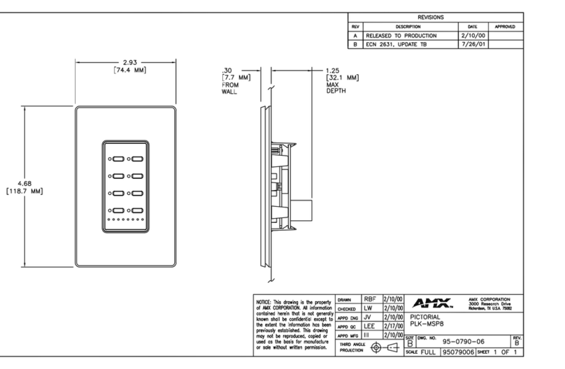
4 11/16" x 2 15/16" x 1 1/16" (119 mm x 74 mm x 26.2 mm)
Weight
Approximately 0.3 lbs. (0.14 kg)
Environmental Requirements
The environmental requirements for the SP-08-E-US are as follows:
•Operating Temperature: 32° F (0° C) to 104° F (40° C)
•Storage Temperature: 4° F (-15° C) to 140° F (60° C)
•Operating Humidity: 5% to 85% RH
Note: Intended for indoor use only.
Power
You can apply power to the SP-08-E-US via any Power-over-Ethernet (PoE)
injector or switch which conforms to the 802.3af standard. Before installing and
mounting the Keypad, test to see that it can receive power.
Note: For mounting space considerations, do not use category cable with
overmold.
Applying Power
Applying power to the SP-08-E-US requires category cable and a PoE injector,
such as the PS-POE-AF-TC (FG423-83) available from AMX. The network
must be connected through the PoE injector to send power to the Keypad. The
category cable should only run through a common building. (A common building
is defined as: Where the walls of the structure(s) are physically connected and
the structure(s) share a single ground reference.)
1. Connect the PoE injector to an AC outlet (~100-240V) using a standard
power cord.
2. Connect the switch category cable to the Data In port on the PoE injector.
3. Using a separate category cable, connect the Data & Power Out port on
the PoE injector to LAN Port on the Keypad.
Button Labeling
Novara Keypads come with a set of clear plastic Key Caps, which are designed
to fit tightly over the pushbuttons, and allow you to place a label on each button
according to the requirements of your particular installation.
Novara Keypads also come with a pre-printed acetate sheet with a range of 50
(pre-cut) button label inserts. The button labels provided will accommodate most
installations, but it is also possible to print your own button labels on acetate for
custom button labeling.
Disassembling the Keypad
This procedure requires a Phillips-head screwdriver.
Important: Before touching the device, discharge the static electricity from your
body by touching a grounded metal object.
1. Use a Phillips-head screwdriver to remove the three screws that secure
the circuit board to the faceplate. All three screws are connected to the
bottom circuit board. (see FIG. 1).
FIG. 1 Remove the screws to separate the circuit board from the faceplate
2. Carefully pull the top circuit board straight up and off the standoffs. Note
the orientation of the circuit board. You must replace it with the circuit
board oriented in the same direction.
Installing Acetate Button Labels
Once the circuit board has been removed, you have full access to the
pushbuttons.
1. Carefully pry the Key Cap off of each pushbutton that you need to re-label.
2. Punch out the desired Button Label from the included acetate sheet. If you
have printed your own custom button labels on acetate, cut each button
label to fit inside the Key Caps.
•Custom button labels must be cut to a 0.472" (12 mm) square to fit
securely inside the Key Caps.
•The thickness of the acetate used must not exceed .004” (0.10 mm).
3. Place the Key Cap face-down, and insert the Button Label into the bottom
of the Key Cap.
FIG. 2 Placing a button label inside a key cap
• Orient the Button Label inside the Key Cap so that the two clips are located
on the left and right sides of the readable text on the Button Label, as
indicated in FIG. 2.
• Be sure to place the Button Label face-down inside the Key Cap (see
FIG. 2), otherwise the label will be seen in reverse once the Key Cap is
installed.
4. Install the key cap on the pushbutton (FIG. 3):
FIG. 3 Installing the key cap on the pushbutton
Note: Verify that the vertical orientation of the Button Label is correct relative to
the keypad.
• Gently press the bottom of the Key Cap (no clip) onto the pushbutton. Do
not allow the clips on either side to engage.
• With the bottom of the Key Cap secured, gently press the top of the Key
Cap. This action will engage both clips simultaneously, and the Key Cap
will snap into place on the push button.
Note: Be careful to follow these procedures closely - the bottom of the Key Cap
must be installed on the pushbutton before the Key Cap clips engage, or there is
a risk of the button being misaligned.
Acetate Button Label
Key Cap (face-down)
Clip
Clip
(face down)
Clip
Clip
Pushbutton on keypad
Key Cap - tilted so that the bottom
of the Cap is placed on the bottom
of the pushbutton first
At this point, do not allow the clips
on the sides of the Key Cap to engage
Press the top of the Key Cap
down to engage both clips at
once, securing the Key Cap
to the pushbutton
Once the clips are engaged,
the Key Cap is secured
to the pushbutton
1
2
3
For full warranty information, refer to the AMX Instruction Manual(s) associated with your Product(s).
3/15
©2015 AMX. All rights reserved. AMX and the AMX logo are registered trademarks of AMX.
AMX reserves the right to alter specifications without notice at any time.
3000 RESEARCH DRIVE, RICHARDSON, TX 75082 • 800.222.0193 • fax 469.624.7153 • technical support 800.932.6993 •
www.amx.com
93-1312-08 REV: A
Reassembling the Keypad
Follow the steps in reverse to re-assemble the keypad. Take care of the
following:
• Be certain that the circuit boards are oriented correctly.
• Use the three screws to secure the circuit board onto the faceplate.
Installation
The SP-08-E-US mounts onto standard 1 gang US and EU back boxes. Each
type of back box must adhere to its own specific safety approvals.
Minimum Internal Clearance for US Conduit Boxes
To ensure a proper fit with sufficient clearance, US-style Novara Keypads
require the following minimum internal dimensions within the conduit box:
US 1-Gang (HWD): 2.9” x 2.1” x 2.5” (74 mm x 53 mm x 64 mm)
These minimum interior dimensions will maintain a minimum .050” (1.27 mm)
clearance.
Important: Before touching the device, discharge the static electricity from your
body by touching a grounded metal object.
Wallbox Mounting
1. Use the cutout dimension for the wallbox to cutout the install surface.
2. Connect category cable to the LAN port on the rear of the keypad.
Note: Use care when feeding excess cabling through the wallbox before
mounting. Do not let the cable kink or tightly bunch inside the wallbox.
CAUTION: If you have connected category cable to the keypad to test whether it
receives power, be sure to unplug the category cable from the PoE injector or
the network switch so the keypad is not receiving power during mounting.
3. Place the keypad on the wallbox; align the screw holes with the mounting
holes and fasten the keypad to the wallbox using the supplied screws.
Configuration
The following sections provide instructions on accessing and configuring the
keypad.
Locating the IP Address of the Keypad
The SP-08-E-US is configured for DHCP addressing by default. The keypad
uses link local addressing as a backup in case the DHCP server is inaccessible.
See the Toggling Between IP Addressing Modes: DHCP and Static IP section for
information on setting a static IP address. Verify there is an active LAN
connection on the controller’s LAN port before beginning this procedure.
1. Using category cable, connect the LAN port on the keypad to your external
network.
2. In NetLinx Studio, select the OnLine Tree tab. You should see the
SP-08-E-US listed among the Unbound Devices.
3. Right-click the SP-08-E-US and select Network Bind/Unbind Device
from the menu that appears. The Bind/Unbind Device dialog opens.
4. By default, the selected keypad appears in the Device to Bind/Unbind
menu at the top of the dialog. If there is more than one Unbound device in
the system, click the down arrow to select which device you want to bind.
5. Select the check box next to the Master to which you want to bind the
keypad. If there is more than one Master in the system, check the specific
Master to which you want to bind the keypad.
6. Click OK to save changes and close this dialog.
7. Select Refresh System (in the Online Tree context menu). The device
should now appear in the Bound Devices folder.
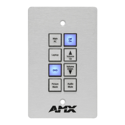
Keypad Layout
FIG. 4 displays the button layout of the keypad.
FIG. 4 Novara SP-08-E-US 8-Button Keypad Button Layout
Simulating the ID Pushbutton
You can press buttons 1 and 2 simultaneously on the keypad to simulate the
functions of a NetLinx device’s ID pushbutton (see FIG. 4).
Toggling Between IP Addressing Modes: DHCP and Static IP
The SP-08-E-US supports both DHCP and static IP addresses. You can use a
static IP address which you can set via a Telnet command (SET IP), or you can
use the factory default static IP address (192.168.1.2).
With the keypad powered and booted up (or in ID Mode), you can toggle
between the DHCP and Static IP modes by pressing and holding buttons 1 and
2. The LEDs on buttons 1 and 2 blink while you keep them pressed. Hold them
until the LEDs begin blinking at double the rate (approximately10 seconds), then
release the buttons.
When you release the buttons, the keypad toggles either from static to dynamic
(DHCP) IP addressing or vice versa and remains in that mode until you use the
buttons to toggle the IP mode again or you perform a factory reset. The keypad
automatically reboots to complete the process.
Note: You must wait until the keypad is finished booting before toggling the IP
address. Pressing the buttons while booting will cause the keypad to restore its
factory default settings.
Resetting the Keypad
To perform a factory reset of the Keypad, press and hold buttons 1 and 2 for
approximately10 seconds during the boot process. The LEDs on buttons 1
and 2 blink while you keep them pressed. Hold them until the LEDs begin
blinking at double the rate (approximately10 seconds.) Release the buttons and
the keypad will reset. During factory reset, the backlight turns off for all buttons,
but all buttons should be back online after 1-2 minutes. If you do not hold in the
reset button until the LEDs begin blinking faster, the reset does not occur. (There
is no soft reboot with the Reset button, but you can perform a soft reboot from
the web pages.)
Note: When you reset a keypad, the keypad is restored to the factory default, so
you will lose all configuration data as the defaults are restored.
Resetting the Factory Image on the Keypad
To restore the factory image on the keypad, press and hold buttons 1 and 2 for
approximately 20 seconds during the boot process. The LEDs on buttons 1
and 2 blink while you keep them pressed. Hold them until the LEDs begin
blinking at double the rate (approximately 20 seconds.) While pressing the
buttons, disconnect and reconnect the cable from the LAN port on the rear panel
of the keypad to restore the factory image firmware.
Channels
Channels on the SP-08-E-US keypads correspond to the button numbers on
each keypad as indicated in FIG. 4.
Port Numbers
The SP-08-E-US appears as port 1.
Additional Documentation
Additional documentation for this device is available at www.amx.com. Refer to
the Novara Ethernet Keypads Instruction Manual for additional details on
installing, upgrading, and wiring the SP-08-E-US.
12
34
56
78

Other manuals for Novara SP-08-E-US

1

This manual suits for next models

1

Other AMX Keypad manuals

AMX Mio Modero Elite User manual

AMX

AMX Mio Modero Elite User manual

AMX Novara CP-1008-US User manual

AMX

AMX Novara CP-1008-US User manual

AMX Mio Modero DMS User manual

AMX

AMX Mio Modero DMS User manual

AMX Metreau DAS-MET-6SRC User instructions

AMX

AMX Metreau DAS-MET-6SRC User instructions

AMX Mio Modero Classic User manual

AMX

AMX Mio Modero Classic User manual

AMX Metreau DAS-MET-6SRC User manual

AMX

AMX Metreau DAS-MET-6SRC User manual

AMX Virtual Keypad NDT-VKP/-ME User manual

AMX

AMX Virtual Keypad NDT-VKP/-ME User manual

AMX Novara SP-08-E-US User manual

AMX

AMX Novara SP-08-E-US User manual

AMX PLK-SBR Guide

AMX

AMX PLK-SBR Guide

AMX DMS Pinnacle Guide

AMX

AMX DMS Pinnacle Guide

AMX DAS-MET-NUM User manual

AMX

AMX DAS-MET-NUM User manual

AMX MIO-DMS Guide

AMX

AMX MIO-DMS Guide

AMX Metreau DAS-MET-6SRC User manual

AMX

AMX Metreau DAS-MET-6SRC User manual

AMX DAS-KP-LCD-G Parts list manual

AMX

AMX DAS-KP-LCD-G Parts list manual

AMX MIO-CLASSIC-S Guide

AMX

AMX MIO-CLASSIC-S Guide

AMX MIO-PRESTIGE-D Guide

AMX

AMX MIO-PRESTIGE-D Guide

AMX MIO-PRESTIGE-S Guide

AMX

AMX MIO-PRESTIGE-S Guide

AMX PLK-DMS Guide

AMX

AMX PLK-DMS Guide

AMX MIO-ATTACHE User manual

AMX

AMX MIO-ATTACHE User manual

AMX Mio Modero DMS User manual

AMX

AMX Mio Modero DMS User manual

AMX Metreau MET-13 User manual

AMX

AMX Metreau MET-13 User manual

AMX Mio Modero DMS Guide

AMX

AMX Mio Modero DMS Guide

AMX Docking Station Mio Attach Parts list manual

AMX

AMX Docking Station Mio Attach Parts list manual

AMX Metreau MET-13 User manual

AMX

AMX Metreau MET-13 User manual

Popular Keypad manuals by other brands

CYP CDPW-K1S Operation manual

CYP

CYP CDPW-K1S Operation manual

Clare Controls ClareVue 5 Replacement manual

Clare Controls

Clare Controls ClareVue 5 Replacement manual

Motostar TACTSTAR manual

Motostar

Motostar TACTSTAR manual

RIDGE RESKEY 14-RK10 quick start guide

RIDGE RESKEY

RIDGE RESKEY 14-RK10 quick start guide

Russound SLK-1 installation manual

Russound

Russound SLK-1 installation manual

Milocks BLEKK installation guide

Milocks

Milocks BLEKK installation guide

CDVI GALEO/W installation manual

CDVI

CDVI GALEO/W installation manual

First Alert FA215KP installation guide

First Alert

First Alert FA215KP installation guide

AES global SnapCOM PRIME Cellular Series Installation & user's instructions

AES global

AES global SnapCOM PRIME Cellular Series Installation & user's instructions

IDS X64 user manual

IDS

IDS X64 user manual

Blink Marine PKP2500SI manual

Blink Marine

Blink Marine PKP2500SI manual

Targus Numeric Keypad with 2 USB ports user guide

Targus

Targus Numeric Keypad with 2 USB ports user guide

RIB ACG9433D manual

RIB

RIB ACG9433D manual

Pasternack PE-9201 User manual & installation guide

Pasternack

Pasternack PE-9201 User manual & installation guide

SCS Sentinel XO 006C + CLES Installation and user manual

SCS Sentinel

SCS Sentinel XO 006C + CLES Installation and user manual

GE NX-148E - Security NetworX LCD Keypad user manual

GE

GE NX-148E - Security NetworX LCD Keypad user manual

ADEMCO 6150PL3 installation guide

ADEMCO

ADEMCO 6150PL3 installation guide

Lenze KF01G Instruction

Lenze

Lenze KF01G Instruction

manuals.online logo
manuals.online logoBrands
  • About & Mission
  • Contact us
  • Privacy Policy
  • Terms and Conditions

Copyright 2025 Manuals.Online. All Rights Reserved.