Timeless Wings SLINGSBY DART 17 Instructions for use
1
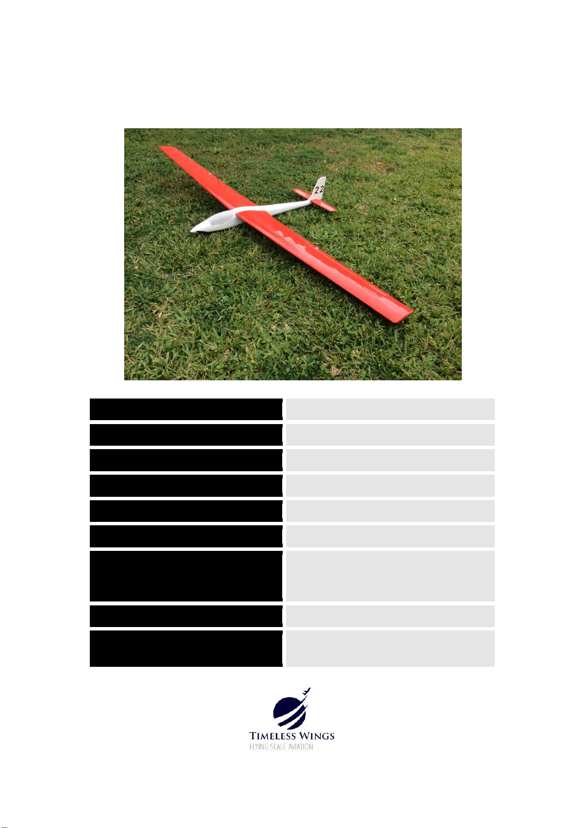
SLINGSBY DART 17
CONSTRUCTION MANUAL Version 1.1
SCALE
1/10
WING SPAN
1700mm (67 inches)
WEIGHT
19 OZS
WING AREA
330 SQ INS
WING AIRFOIL
SELIG 3021
WING LOADING
8.3 OZS/SQ FT
MOTOR & PROP
2040 brushless in-runner R/C car motor
driving a 5.1 x 3.1 inch folding prop, or
up to 28mm outrunner (with mods)
LIPO
2S x 1300mAh
POWER
Measured 104W @13.2A, Surpass Hobby
2040 in-runner, 3200kv, on 2S

2
PRELIMINARY NOTES
This model came about in early 2020 during a period of Corona Virus restrictions,
and was designed to use items at hand at the time. Specifically, it was designed to be
a small balsa build to use the diminutive 5.1 x 3.1 inch folding props I had on hand.
These suit a 2mm to 2.3mm shaft, so originally an old Hacker B20 motor was fitted.
This has been recently replaced with an inexpensive contemporary Surpass Hobby
20mm R/C car motor with a 2.3mm shaft, which works really well in this application.
Although designed for a 20mm in-runner, the nose is wide enough to fit up to a
28mm outrunner if desired, but some modifications will be required. The
construction notes assume previous experience building similar models.
Despite its small size, this model is very efficient with its Selig 3021 airfoil and keeps
up very well with the larger gliders at our field. Penetration is especially good.
Whilst clearly only “semi-scale”, this model was designed to keep the character of
the original Dart with its small tail volume compared to the wing. This necessitates a
Centre of Gravity further forward than you would normally expect. A small amount
of lead ballast will likely be necessary to achieve the CG on the plans. The first flight
of the prototype was with a much too rearward CG, which, combined with large
control throws made for a very unstable model! The CG on the plans should
definitely be adhered to!
This Dart could easily be built as a slope-soarer by using a solid balsa nose instead of
the motor. This construction manual assumes that the builder is familiar with
“traditional balsa construction methods”. The construction notes and plans have
some small changes from the original prototype which reflect improvements, and
should take precedence over any differences noted compared to the photographs.
The manual will assume that a kit of all parts has been cut before assembly
commences. Metric and imperial sizes are used interchangeably. The parts layout
files are recommended only. These, and the plans may be used as desired for private
purposes. For commercial use, please contact the designer.
Graham Reddin
Sydney, Australia
May 2021
E: [email protected]om
W: https://timelesswings.com/
3
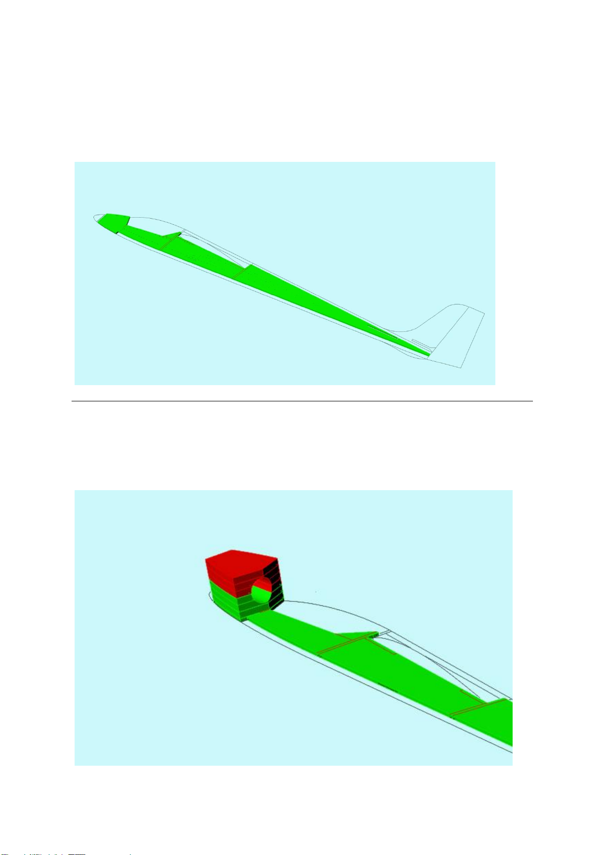
FUSELAGE CONSTRUCTION
1. Mark the position of formers on the fuselage sides, then pin the right fuselage side to
the building board (50mm thick Styrofoam insulation with baking paper on top works
well as a building board). Note that the left and right fuselage sides are different
because of the staggered position of the pushrod exits.
2. Make up the noseblock assembly in two halves, by gluing 3 LHS pieces together (shown
in red), and 3 RHS together (shown in green). The location of the motor cut-out is now
drawn on front and back (refer to plan for location) then removed using a coping saw.
The two halves can then be glued together, then glued to the fuselage RHS.
4
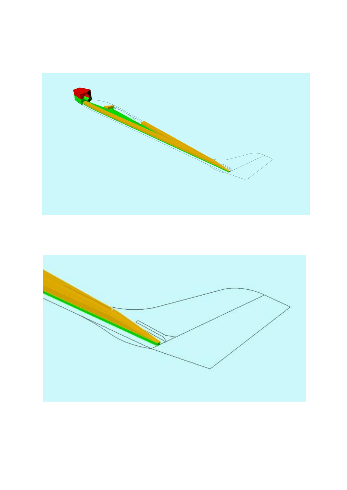
3. Glue the 6.4mm balsa fuselage doublers to the fuselage RHS as shown. Separately, glue
the 6.4mm balsa fuselage doublers to the fuselage LHS.
_____________________________________________________________________
4. Chamfer the rear of the fuselage doublers where the sides will be drawn together

5
5. Glue the fuselage formers all in position as shown, along with the 3.2mm ply wing
mounting plates and motor mount formers.
_____________________________________________________________________
6. Glue fuselage LHS assembly to fuselage RHS assembly.

6
7. Glue the 6.4mm balsa forward fuselage bottom sheeting in place, as well as scrap
1/16”x 1/8”balsa wing seating strips (which are to allow for the wing dihedral).
8. Glue the rear fuselage sides together, then glue in the 1/8” OD plastic sleeves for the
pushrods. Note that these are crossed to give the best geometry.
7
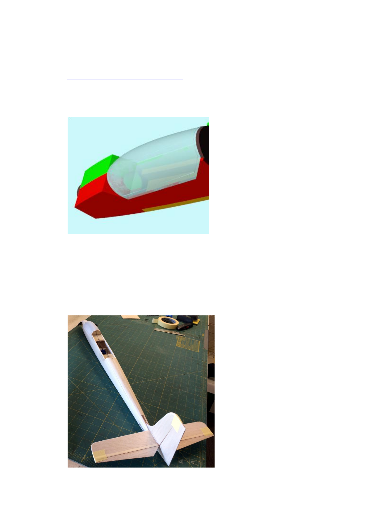
9. Before the fuselage is shaped you will need to complete the canopy, which is used as a
shaping guide for the forward fuselage. The prototype model used a 3D printed
canopy, from 2 x 0.4m layers of clear PLA –canopy file available from here:
https://timelesswings.com/downloads
The 2 layers of clear PLA may distort if left in a hot car, but should be fine for normal
use on the model. If preferred, PETG can be used for printing as it is more heat
resistant. Those without access to a 3D printer may wish to form the canopy from
foam or balsa, hollowed as appropriate.
_____________________________________________________________________
10. Add the remaining 6.4mm balsa fuselage top and bottom sheeting, leaving a slot in the
rear section for the fin. Generously carve and sand fuselage to approximate the shape
shown on the plans. Shape the fin and rudder then glue the 3/16” balsa fin in position.
Make up the tailplane and elevator from 1/8” balsa and 1/8” x 1/4” bass or spruce (as
shown on plan) shape, and glue to fin. Note: the tailplane and elevator should be
hinged before assembly. (Prototype used iron-on film as a hinge). Fit skid under rear
fuselage.

8
WING CONSTRUCTION
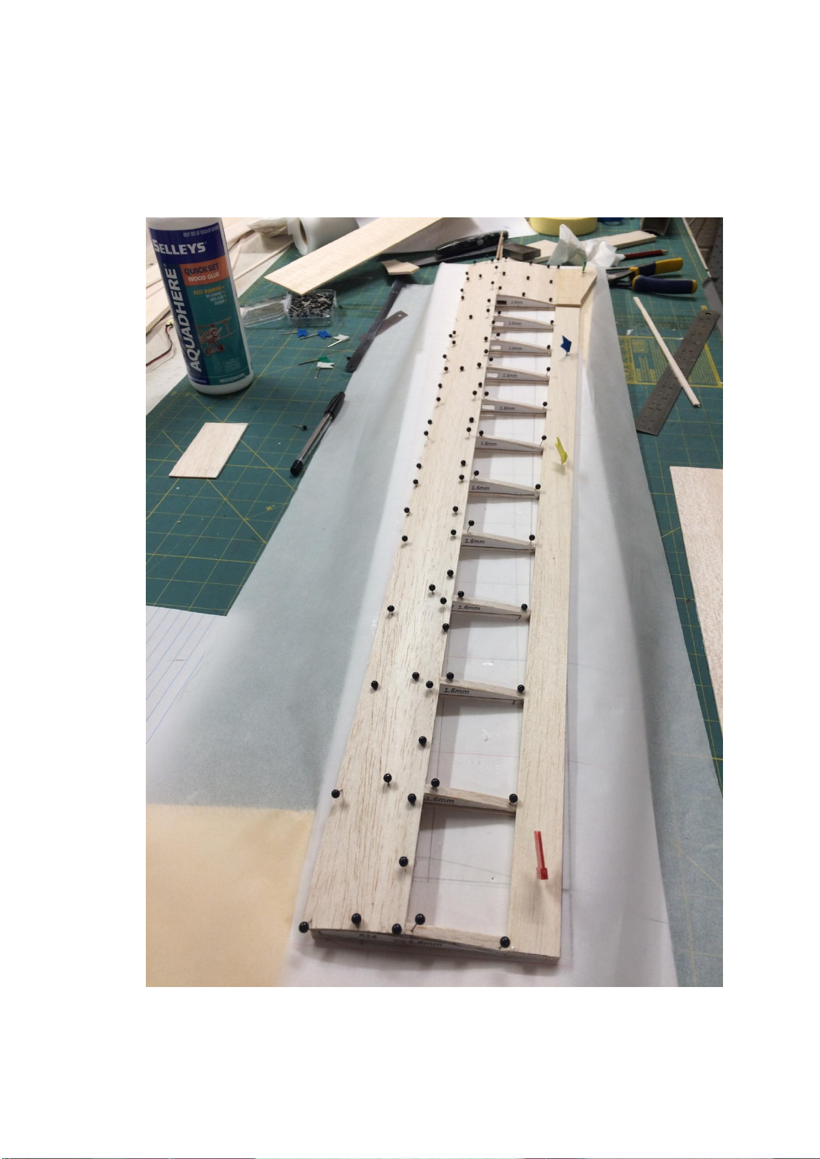
11. Tape the left wing plan to the building board with a layer of baking paper on top, then
pin in place the 1/16” sheeting and 1/4” trailing edge , and glue cap strips in place as
show below.

9
12. Glue the front and rear dihedral braces to the spar, then thread the ribs onto the spar
and glue this assembly into position over the sheeting and cap-strips. PVA works well
here. Glue the false LE in place.

10
13. Fit and glue front and rear sections of 1/8” (3.2mm) balsa root rib R1, as well as TE
doubler and scrap ¼” square balsa front wing bolt reinforcement.
11
14. Glue on the LE sheeting using PVA.
12
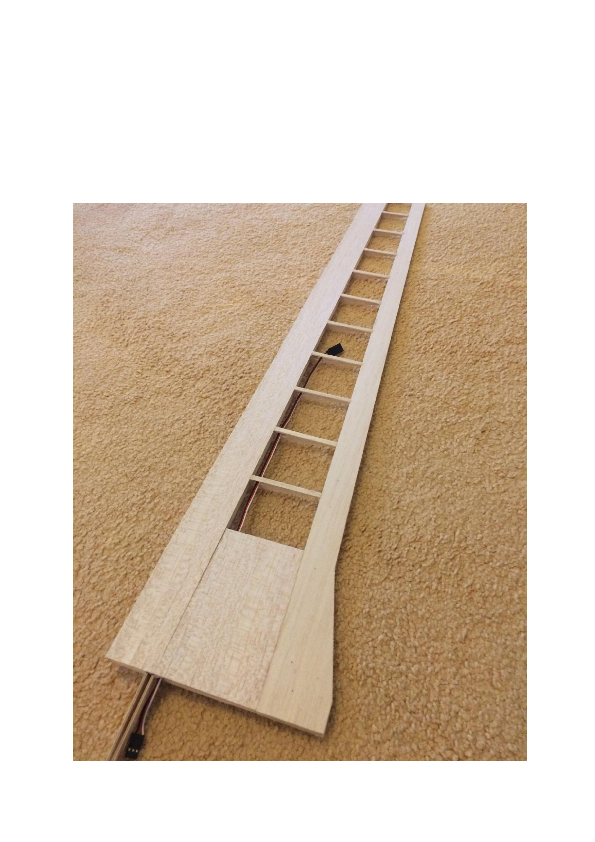
15. Trim and sand the LE and wingtip and fit 6.4mm balsa LE left and WINGTIP. Sand to
shape. Thread the aileron servo extension lead through the appropriate holes in the
ribs. Depending on how you choose to fit the wing servos, you may add the servo
mount sheeting and reinforcements now, or after the two wing halves are joined.
Underside of left wing shown below.
13
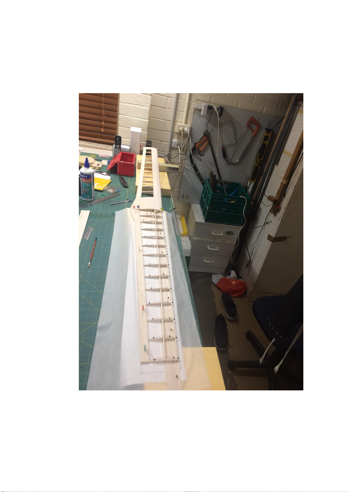
16. Build the right wing over the plan, propping up and joining the left wing to the right
wing during construction before the top sheeting is added. A hole is made in the
bottom RHS centre-section sheeting for the aileron servo leads to exit.
14
17. Once the wing structure has been completed, drill holes for 2 x 4mm wing bolts (use
location shown on the plans) then present wing up to fuselage, marking the position on
the ply fuselage wing mount plates where the bolts come through. Drill and tap holes
for the 4mm bolts in the ply or for alternative blind retention nuts.

15
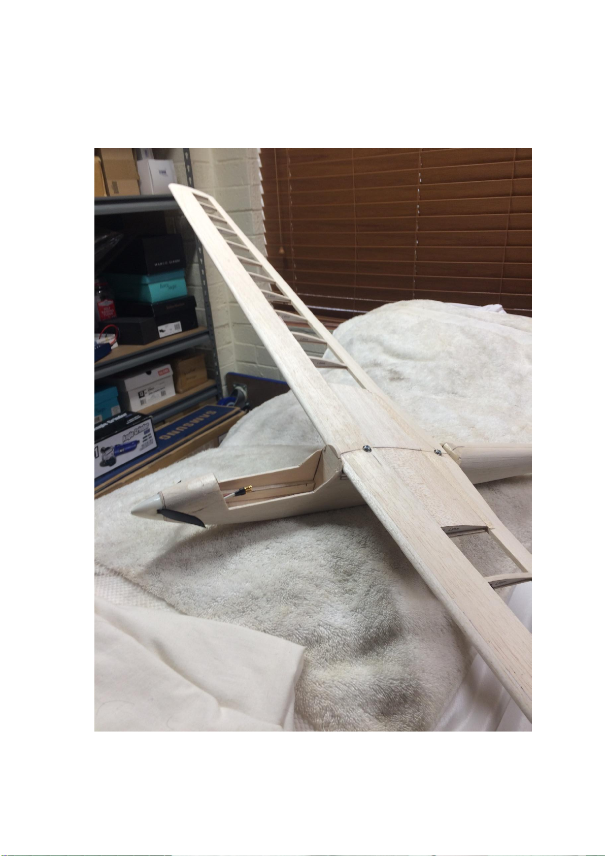
18. Make up the fuselage over-wing fairing as shown on the plans, and temporarily fit in
place to shape. The model is now structurally complete, and should look something like
this:

16
FITOUT
19. Decide how you wish to hinge the ailerons; then cut out from the wing and bevel to
suit. The prototype used clear tape, top-hinged. The rudder can be hinged according to
preference. Fit the aileron servo attachments of choice, if not already done earlier.
The prototype was covered with HobbyKing iron-on covering, which goes on easily and
gives a great result. HXT900 servos are fitted side by side in the prototype. Smaller
servos would be fine too. Fit control horns and associated connectors etc.
17
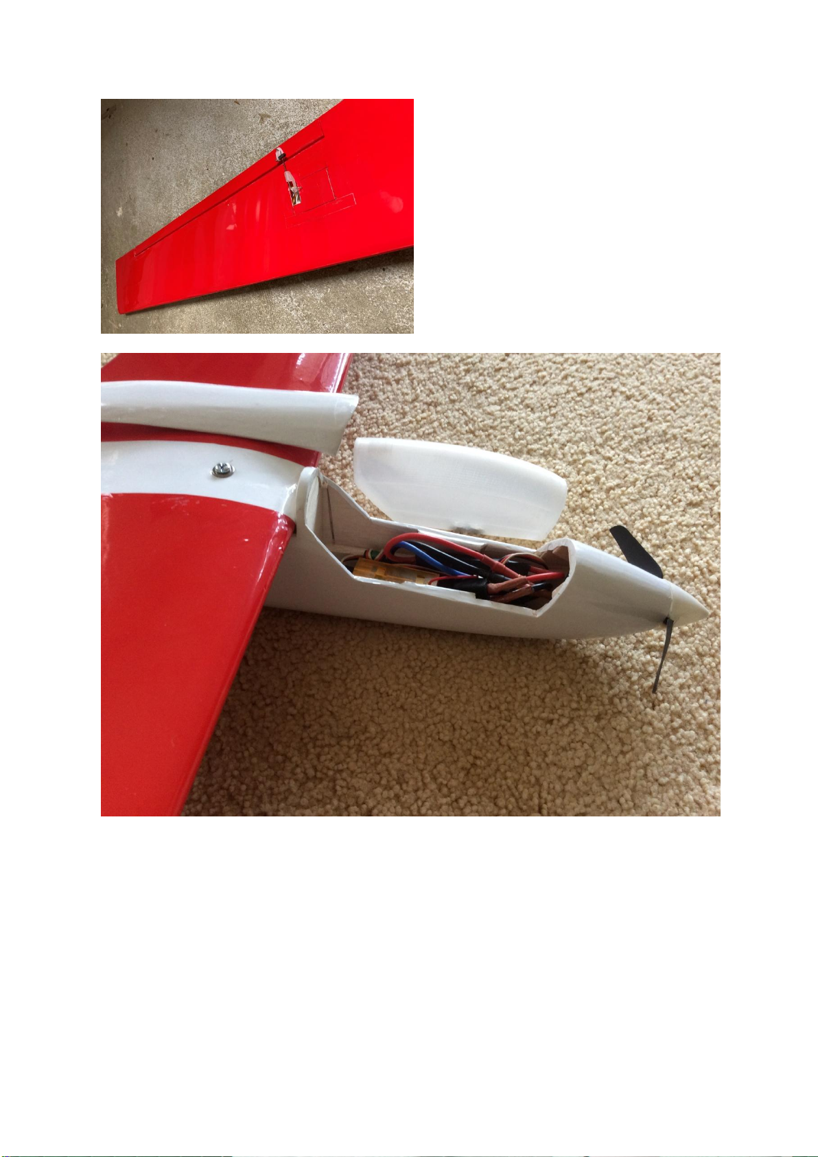
Fit the motor and radio gear. Air holes for motor cooling have not been added at this point
in time, but should be considered for motor longevity. If using a 3D-printed canopy, hollow
the bottom with a soldering iron to fit the flight battery. Rare earth magnets were used to
hold canopy in place. The fairing over the top of the wing is held on with clear tape.

18
FLYING
Control throws (all measured at widest point of surface)
ELEVATOR: 8mm UP /4mm DOWN. AILERONS: 8mm UP/4mm DOWN. RUDDER: 20mm
LEFT/RIGHT. Expo to taste.
The importance of a forward Centre of Gravity position cannot be emphasised enough with
this model! Do balance as shown on the plan, even if a small amount of lead in the nose is
necessary, as it probably will be. The CG shown gives a neutrally stable model which
performs well, and is responsive with good glide and penetration. It flies faster than a
floater like a Radian or Aquila, but does not disgrace itself in their company especially once
the wind picks up.
This model would perform well on the slope without a motor too. On the flat field it has
done basic aerobatics including loops and rolls.
Enjoy!
A short flight video can be found here:
https://www.youtube.com/watch?v=oBufEUaoIu4

19
Table of contents
Other Timeless Wings Toy manuals


Popular Toy manuals by other brands


RC Groups
RC Groups SLICK-EPP installation instructions

Minicraft Models
Minicraft Models USAF WC-130J manual

marklin
marklin 46717 instruction manual

Fisher-Price
Fisher-Price FORD F-150 L6348 Owner's manual & assembly instructions

LEGO
LEGO Klando 2015 Campus 4000018 Assembly guide

Max-Thrust
Max-Thrust Mini Viper Jet Assembly and operating manual


