Timeless Wings MIG-15UTI User manual

1
Timelesswings.com
PRINTING AND ASSEMBLY GUIDE MIG-15UTI VERSION 1.1 10 SEPTEMBER 2023

2
Timelesswings.com
PRINTING AND ASSEMBLY GUIDE MIG-15UTI VERSION 1.1 10 SEPTEMBER 2023
SCALE
1/13.5 approx
WINGSPAN
750mm (29.5 inches)
FLYING WEIGHT
640g (22.5 ounces)
WING AREA
160 SQ IN
WING LOADING
20 OZS/SQ FT
EDF
X-FLY Galaxy or FMS 50mm EDF or
similar 4S unit
LIPO
4S x 1300mAh

3
Timelesswings.com
PRINTING AND ASSEMBLY GUIDE MIG-15UTI VERSION 1.1 10 SEPTEMBER 2023
Mig-15UTI - history
First flying in 1949, the MiG-15 UTI (dubbed “Midget” by NATO) was a two-seat trainer
development of the MiG-15 (“Fagot”), which took to the air a year and a half after the
single-seater Installation of the second seat required a small plug in the front fuselage
along with space behind the standard cockpit being rearranged, at the expense of fuel
tankage..Many MiG-15UTIs carried a variety of under-wing auxiliary fuel tanks to make up
for this shortfall.
The rear cockpit was slightly raised to give the instructor a better view. Largely due to the
drag from the poor shape of the extra cockpit, the high-speed performance was significantly
worse than the single-seat Mig-15, but combat handling characteristics were identical.
Ultimately, the MiG-15 UTI had a longer production run and in greater numbers than the
single-seater, thus becoming one of the world’s most-produced jet aircraft. At the time of
writing the MiG-15UTI is still in use as a military jet trainer in North Korea, nearly 75 years
after its first flight.

4
Timelesswings.com
PRINTING AND ASSEMBLY GUIDE MIG-15UTI VERSION 1.1 10 SEPTEMBER 2023
NOTES ABOUT THE DESIGN PROCESS AND PRINTING OPTIONS:
The MiG-15UTI files include G-code files and .3MF files for all parts, sliced on the free Prusa slicer
(version 2.5.2).
In the first instance, the G-code files should be generic enough to give acceptable results when
loaded directly on a cartesian printer with at least a 200 x 200 x 200mm build volume, with direct
drive or Bowden extruder, but individual results may vary.
Alternatively, the Prusa slicer is easy to use, to load the corresponding part .3MF file as a project,
and to change any applicable settings that are not working for your specific print job. These parts
have not been tested in other slicers, so for predictable results the Prusa slicer should be used if the
G-codes do not give a satisfactory result.
Except for the nose inlet, integrated motor mount, canopy, and wing &fuselage joiners which are in
normal PLA, all parts are printed from LW-PLA. Clear Gorilla Glue is a good alternative to CA and
accelerator for joining LW-PLA parts.
The LW-PLA components were printed with E-Sun LW-PLA which gave excellent results. E-Sun PLA+
was used for PLA parts and can be recommended. Other filaments may require a small adjustment
to print temperatures and/or extrusion multiplier to give similar results.
Design methodology:
This model has been designed so that all components are solids and are printed with an outer skin
and internal infill. Depending on variables such as nozzle condition, extruder condition, bed
temperature sensor accuracy, filament condition etc. it may be necessary to tweak some of the print
settings to give the best results. The .3MF files when loaded as a project into Prusa slicer will
populate the Print Settings, Filament Settings and Printer Settings with the generic values generated
by the designer, as well as loading the component STL file.
The drop down “Printer Settings” menu can be used to load the default settings specific to your
printer (such as prime line G-code etc.) This may be helpful especially for Bowden printers.
Additionally, any changes that you make in the Print Settings menus or Filament Settings menus can
be saved (if desired) under another name from the “Save Current….” option adjacent to the drop-
down menu boxes at the top left of the Prusa window.
LW-PLA parts should be printed one at a time. Weights and times are just a guide, but should be
close to default file values, and are conservative giving strong parts. For this model, gyroid infill
works best on fuselage components, and cubic infill for the wings
The default print speed set in most of the G-code files is 40mm/sec, which is quite high for LW-PLA
but gives an acceptable print result, saving hours of print time over the often-used speeds of around
30mm/sec.. This may be reduced of course if desired.

5
Timelesswings.com
PRINTING AND ASSEMBLY GUIDE MIG-15UTI VERSION 1.1 10 SEPTEMBER 2023
If covering with glass cloth/WBPU or epoxy the extrusion multiplier for PLA parts may be reduced
from 0.7 to around 0.65 or lower..
By default, a small amount of part cooling fan is used on all parts. If necessary, better layer adhesion
may be achieved with the fan off, if the print result is acceptable in other respects.

6
Timelesswings.com
PRINTING AND ASSEMBLY GUIDE MIG-15UTI VERSION 1.1 10 SEPTEMBER 2023
PART nose inlet
•PLA
•Print weight: 10.68g
•Print time: 47 mins
PART F1
•LW-PLA
•Print weight: 50.95g
•Print time: 5hr 22min

7
Timelesswings.com
PRINTING AND ASSEMBLY GUIDE MIG-15UTI VERSION 1.1 10 SEPTEMBER 2023
PART F2
•LW-PLA
•Print weight: 54.26g
•Print time: 5hr 52min
PART F3
•LW-PLA
•Print weight: 47.88g
•Print time: 6hr 33min

8
Timelesswings.com
PRINTING AND ASSEMBLY GUIDE MIG-15UTI VERSION 1.1 10 SEPTEMBER 2023
PART F4
•LW-PLA
•Print weight: 24.83g
•Print time: 3hr 4mins
PART W1L
•LW-PLA
•Print weight: 29.31g
•Print time: 3hr 28min
•W1R is mirror image of
this part

9
Timelesswings.com
PRINTING AND ASSEMBLY GUIDE MIG-15UTI VERSION 1.1 10 SEPTEMBER 2023
PART W2L
•LW-PLA
•Print weight: 24.45g
•Print time: 3hr 31min
•W2R is a mirror image of
this part
PART wing tip L
•LW-PLA
•Print weight: 2.38g
•Print time: 22 mins
•Wing tip R is a mirror
image of this part

10
Timelesswings.com
PRINTING AND ASSEMBLY GUIDE MIG-15UTI VERSION 1.1 10 SEPTEMBER 2023
PART ailerons L&R
•LW-PLA
•Print weight: 8.42g
•Print time: 1hr 45mins
•A brim may be necessary
if print bed adhesion is
not good
PART elevator L&R
•LW-PLA
•Print weight: 8.11g
•Print time: 1hr 31min
•A brim may be necessary
if print bed adhesion is
not good

11
Timelesswings.com
PRINTING AND ASSEMBLY GUIDE MIG-15UTI VERSION 1.1 10 SEPTEMBER 2023
PART tailplane L
•LW-PLA
•Print weight: 4.74g
•Print time: 1hr 12mins
•A brim may be necessary
if print bed adhesion is
not good
•tailplane R is a mirror
image of this part
PART wing fences
•LW-PLA
•Print weight: 2.94g
•Print time: 26mins

12
Timelesswings.com
PRINTING AND ASSEMBLY GUIDE MIG-15UTI VERSION 1.1 10 SEPTEMBER 2023
PART canopy
•Clear (natural)PLA or
solid colour PLA if
desired
•Print weight: 32.29g
•Print time: 3hr 17mins
•A brim may be necessary
if print bed adhesion is
not good
PART integrated
motor mount & F2
mounting brackets
•PLA
•Print weight: 17.02g
•Print time: 1hr 21 min
•A brim may be
necessary if print bed
adhesion is not good

13
Timelesswings.com
PRINTING AND ASSEMBLY GUIDE MIG-15UTI VERSION 1.1 10 SEPTEMBER 2023
PARTwing joiner tabs
•PLA
•Print weight: 2.33g
•Print time: 8 mins

14
Timelesswings.com
PRINTING AND ASSEMBLY GUIDE MIG-15UTI VERSION 1.1 10 SEPTEMBER 2023
FORWARD FUSELAGE ASSEMBLY
•Cut fuselage alignment pins to a 20mm length from 1.75mm filament and insert into
formers as shown. Trim as necessary to fit. Cutting the filament ends at an angle helps to
insert in the alignment holes in the parts.
•Check that all parts fit together snugly. Separate parts again then apply glue to the front
and rear of F1. Carefully reassemble parts and clamp until dry.
•Glue 10mm diameter x 3mm thick hatch magnet into the hole in the front of F2.
•Glue mounting brackets in rear of F2, ensuring closed end of bracket faces the front.

15
Timelesswings.com
PRINTING AND ASSEMBLY GUIDE MIG-15UTI VERSION 1.1 10 SEPTEMBER 2023
REAR FUSELAGE ASSEMBLY
•Take two lengths of elevator piano wire pushrods and push through the pushrod channels in F3
and F4 until they slide freely. The channels will take up to 1.2mm (0.047in) diameter wire
(maximum), but 0.8mm (0.031in) was used on the prototype and works fine.
•Cut fuselage alignment pins to the lengths shown on the diagram below from 1.75mm filament
and insert into formers as shown. Do not be tempted to use solid pins here as a bit of flex is
necessary to allow for the pushrod angle. Check that all parts fit together snugly. Separate F3 and
F4 again then apply glue to the front of F4, ensuring glue does not get into the pushrod channels
or on the pushrods . Carefully reassemble parts and clamp until dry. Set aside for now.
CANOPY ASSEMBLY
•Glue 10mm diameter x 3mm thick canopy magnet into the hole in the rear of the canopy
. IMPORTANT! Make sure that the polarity of the magnet is correct so it attracts the
hatch magnet in F2.
•Using a soldering iron or hotmelt glue gun nozzle, melt away the bottom section of the
canopy , following the engraved line.

16
Timelesswings.com
PRINTING AND ASSEMBLY GUIDE MIG-15UTI VERSION 1.1 10 SEPTEMBER 2023
WING ASSEMBLY
•Cut wing alignment pins 20mm in length from 1.75mm filament and insert into holes as shown.
Check that all parts fit together snugly. Some light sanding of mating surfaces with a flat block
may be necessary. Note that the wing tips are not added at this stage to make fitting the ailerons
easier.
•Glue parts W1 and W2 together and clamp until dry.
•Glue flat wing joining plates into the wing root
•Clear out the holes in the top of W1 for the additional wing fence and trim and sand the tabs on
the bottom of the wing fence until it fits snugly. Glue in place
•Cut aileron CA hinge sheet approx. 15mm x 18mm, two per aileron, trim to fit then glue aileron
in place, leaving a gap of about 0.5mm to ensure free movement.
•Glue wing tip in place
•Repeat for other wing

17
Timelesswings.com
PRINTING AND ASSEMBLY GUIDE MIG-15UTI VERSION 1.1 10 SEPTEMBER 2023
AILERON SERVO INSTALLATION
•Tape an aileron extension lead (about 450mm) to each aileron servo and
feed through the hole in the wing assembly. Make sure the servo arm is
attached and centred, then glue the servo in place with hot melt glue.
NOTE: a servo thicker than 8mm will protrude slightly from the wing
undersurface.
•Fit the 0.8-1.2mm pushrods with small clevises at each end. (see photo
below)
WING ATTACHMENT
•Cut WING JOINER from 6mm OD carbon tube or rod 220mm long, and place
centrally through the hole in F2. Do not glue.
•Slide the wing assemblies onto the WING JOINER , feeding the aileron servo leads
into the hole in the fuselage. Carefully drill a pilot hole through the fuselage and
the wing joiner tabs.. Join with self-tapping screws about 10mm in length. (see
photo above)

18
Timelesswings.com
PRINTING AND ASSEMBLY GUIDE MIG-15UTI VERSION 1.1 10 SEPTEMBER 2023
TAILPLANE & ELEVATOR ASSEMBLY
•Cut CA hinge sheet to dimension approx. 14 x 18mm for the tip and 17 x 18mm for the
root of each elevator, and attach the elevators to the tailplane halves.
TAIL ATTACHMENT
•Cut rear tailplane spar from 3mm carbon rod 96mm long, and place centrally through the rear
(circular) holes in F4. Do not glue. Cut short front tailplane alignment spar from 3mm carbon
rod 32mm long, and place centrally through the front(elongated) holes in F4. Do not glue.
•Slide the tailplane/elevator assemblies onto the spars then carefully glue L and R tail
assemblies to F4, ensuring the elevators are not glued. Clamp until dry.

19
Timelesswings.com
PRINTING AND ASSEMBLY GUIDE MIG-15UTI VERSION 1.1 10 SEPTEMBER 2023
INTEGRATED MOTOR & SERVO MOUNT ATTACHMENT
•Cut 2 x 20mm lengths of 1.75mm filament for the alignment pins, and place in the 2
inner holes on the left and right side of F3.
•Glue the integrated motor mount in place, noting that the two flat servo mounting
plates face UP
•Wrap the rear of the EDF shroud in masking tape so that the EDF fits snugly in the
MOTOR & SERVO MOUNT. The rear of the EDF sits level with the rear of the MOTOR &
SERVO MOUNT. The motor leads exit the tailpipe through the keyhole shaped slot in
F5. Secure the fan with small beads of hot melt glue joining the tape to the mount.
These can be easily removed if desired for fan replacement.

20
Timelesswings.com
PRINTING AND ASSEMBLY GUIDE MIG-15UTI VERSION 1.1 10 SEPTEMBER 2023
ELEVATOR SERVO ATTACHMENT
•Each elevator is driven by its own micro servo, one of which is connected to the elevator channel
in the receiver, the other needs to be mixed through an auxiliary channel. A servo extension lead
may be required.
•Space is tight, and requires a micro servo of 8mm thickness. Any servo much larger than this (20
x 19.6 x 8.0mm) may not fit, or may require internal parts of F2 to be trimmed. Use hot melt glue
to attach .
•Attach 0.8-1.2mm pushrods with clevis to servo end first, then bend, trim and connect at the
elevator end last. Adjustments can be made on the transmitter if necessary to zero the trim.
Table of contents
Other Timeless Wings Toy manuals
Popular Toy manuals by other brands
Mega Bloks
Mega Bloks NANO Off Shore Racing 5983 instructions

Xtrem Bots
Xtrem Bots Andy XT380970 instruction manual
Eduard
Eduard Ju 87B-1 seatbelts STEEL quick start guide
Faller
Faller Mountain Chalet manual

Helion
Helion Four 10SC quick start guide

Hasbro
Hasbro Nerf Atom Blasters Cyclotron 45519 instructions

DAAN Groups
DAAN Groups VOLTZ TOYS DG-81919 user manual
MGA Entertainment
MGA Entertainment little tikes Splish Splash Sink and Stove... manual
Hasbro
Hasbro Transformers Animated Bulkhead 83955 instructions
Faller
Faller 120193 manual
REVELL
REVELL AIRBUS HELICOPTERS EC 135 user manual
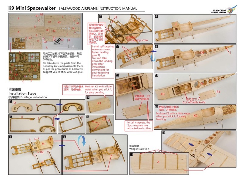
Dancing Wings Hobby
Dancing Wings Hobby K9 Mini Spacewalker instruction manual
