Caley Coaches CL02/2a Instruction Manual

Caley Coaches CL02/2a Building Instructions
Page 1
0141 772 5537 Jim Smellie,
15 Tay Crescent,
Bishopbriggs,
Glasgow, G64 1EU.
CL02/2a Caledonian Railway
Classes 812 & 652 0-6-0
locomotives
C.R. numbers 282-293,325-328, 652-659, 661-665, 812-878
L.M.S. numbers 17550-17645
BUILDING INSTRUCTIONS
Parts required to complete
1 Motor Mashima 1220 “flat can” or similar recommended.
2 Gearbox High Level Loadhauler recommended.
[High Level Kits, 14 Tudor Road, Chester-le_street, Co.
Durham, DH3 3RY.
www.highlevelkits.co.uk]
3 Wheels 5'0" diameter, 16 spoke driving wheels and
4'0" diameter, 12 spoke tender wheels
4 Paint and transfers.
5 Couplings.
Section 1 Parts list
Please check the contents of your kit and inform me of any shortages. If for any
reason you wish to purchase parts separately, I can give you a quote for any part
unless it is on an etched fret. Normally complete frets only are available.
Please also read the General Instructions supplied if you are not familial with
etched kit constuction in general and Caley Coaches productions in particular.
The supplied parts, together with these instructions, assume that you are building

Caley Coaches CL02/2a Building Instructions
Page 2
the kit with a compensated chassis. If you are not, please return the compensation pack to me with
a note of your name and address and I'll be happy to forward the required bearings and modified
instructions to enable you to build rigid chassis.
N.B. Numbers in brackets following a part name are the quantity supplied when other than 1; numbers
preceding a part name are identification numbers which will be found along side the part on the
appropriate etch. Wire etc. will be found taped to the box lid.1 Loco body etch containing :-
1 Footplate, 2 Footplate valances (2), 3 Buffer beam, 4 Drag beam, 5A 812 cab sides (2), 5B 652 cab sides
(2), 6 Cab front, 7 Cab floor side supports (2), 8 Cab floor rear support, 9 Cab floor, 10 Splasher box
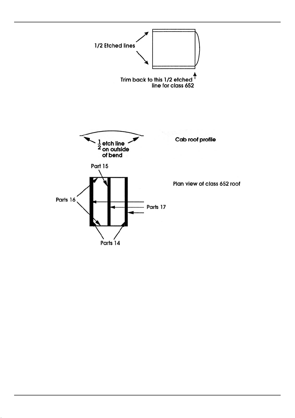
sides (2), 11 Splasher box tops (2), 12 Cab roof, 13 812 roof rear strip, 14 Roof front and rear strips (2), 15
Roof centre strip, 16 Roof gutter strips (2), 17 Cab roof stanchions (4), 18 652 upper frames (2), 19F 812
front upper frames (2), 19R 812 rear upper frames (2), 20 Middle splasher sides (2), 21 Middle splasher
tops (2), 22 Front splasher/sandbox sides (2), 23 Front splasher/sandbox tops (2), 24 Smokebox front,
25 Smokebox rear saddle, 26 Firebox front, 27 Centre steps (2), 28 Rear lower steps (2), 29 Rear upper
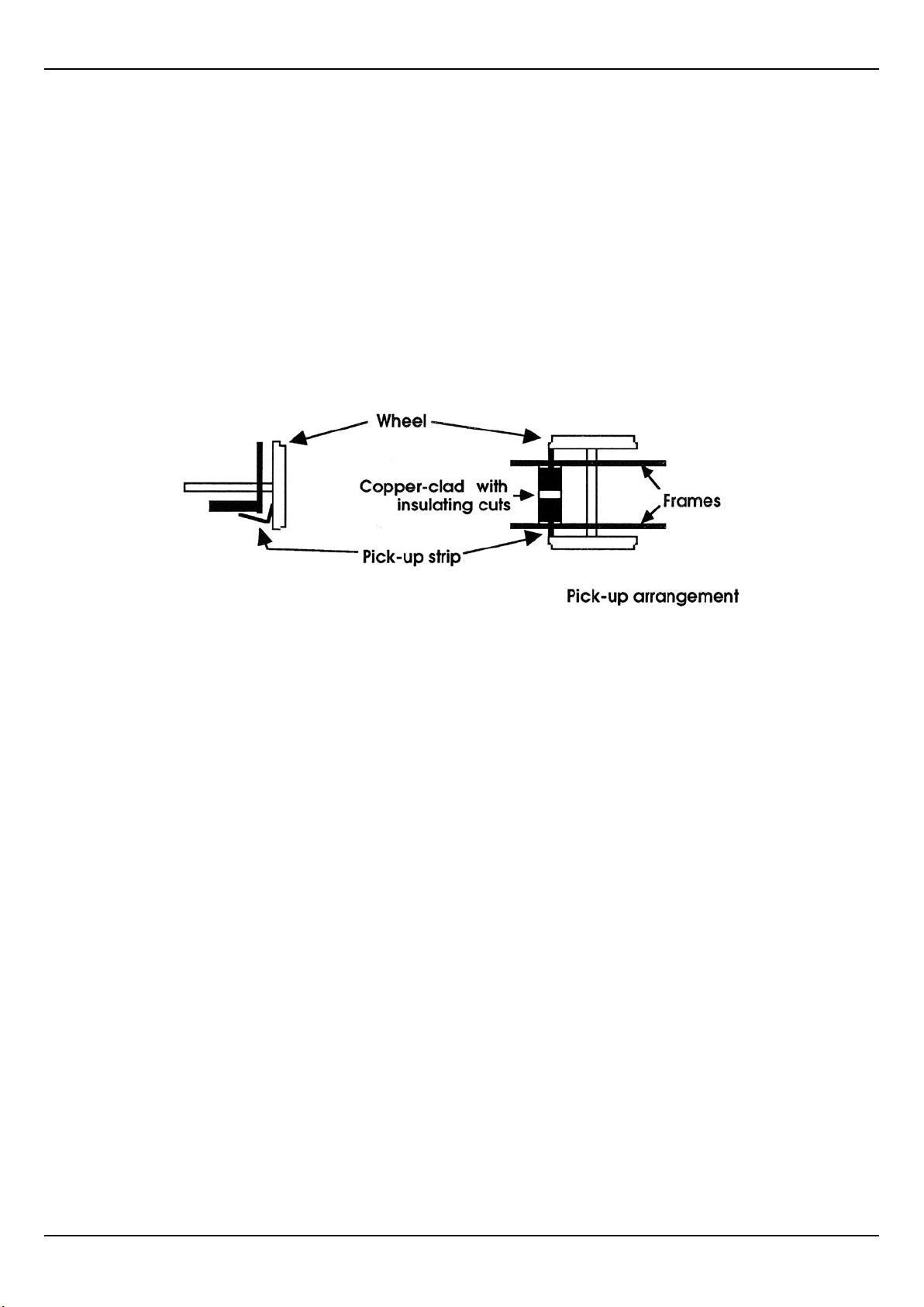
steps (2), 30 Spectacle surrounds (2), 31 Cab opening beadings (2), 32 Boiler bands (5), 33 Reversing rod
(652), 33B Reversing rod (812), 34 Reversing lever, 35 Strips for lamp irons (3).
2 Additional etched loco body parts :-
Boiler/smokebox/firebox, Inner smokebox wrapper, Outer smokebox wrapper.
3 Loco chassis etch containing :-
Chassis frames (2), Brake blocks (6), Brake hangers (6), 7 Brake pull-rods (2), Centre wheel balance
weights (2), Outer wheel balance weights (2), Class 812 centre axle coil springs (2), S1- S4 Frame spacers
(1 each of OO, EM and P4)
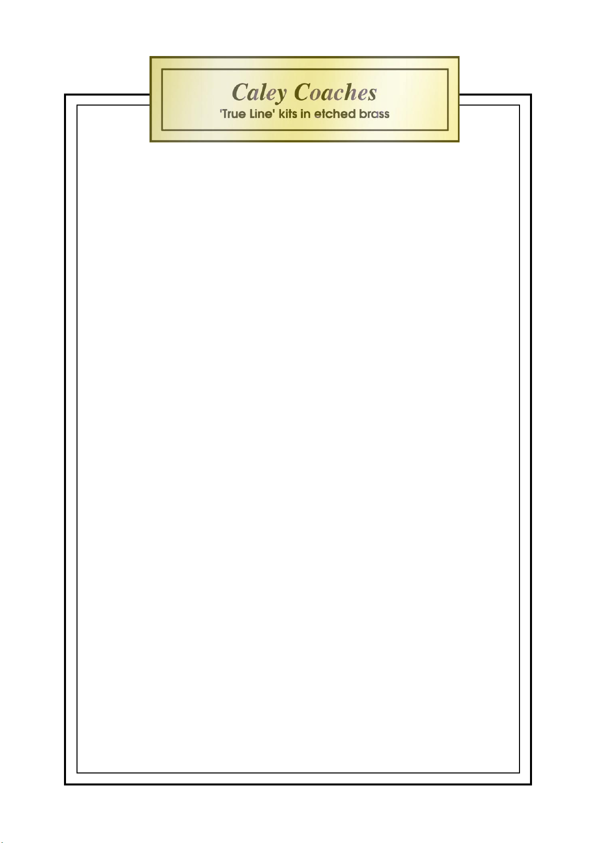
4 Steel coupling rod etch.
5 Cast fittings :-
Chimney, Standard dome, Flat topped dome, Smokebox door, Smokebox door dart, Backhead,
Ramsbottom safety valve, Ross pop safety valve, Steam chest cover, Sandbox fillers (2), Reversing lever,
Cylinder lubricators (2 each of two different styles), Sandboxes (2), Westinghouse pump, Westinghouse
pipe, Steam pipe, Vacuum pipe.
6 Turned brass fittings :-
Buffers (2), Short handrail knobs (3), Medium handrail knobs (6), Whistle.
7 Miscellaneous parts:-
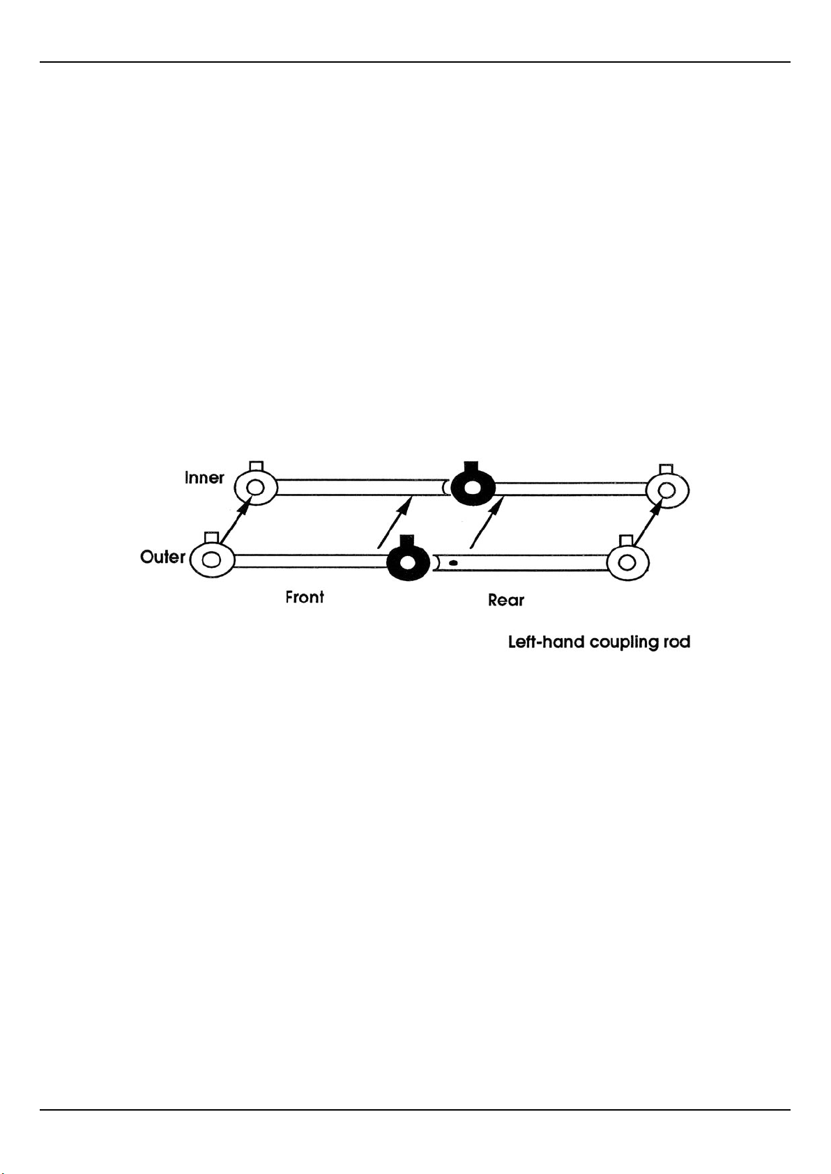
Compensation pack, Boiler tube, 0.45mm wire (4), 0.9mm wire (2), Brass rod, Copper-clad strip, Phosphor-
bronze strip, 10BA nuts (2), 10BA bolts (2), Insulated wire.
Section 2 Footplate
2.1 Remove the footplate (part 1) from the body etch, remove and store carefully the lamp-iron strips
(part 35) contained within it.
2.2 Solder the footplate valances (part 2) into the locating grooves on the underside of the footplate,
checking that the footplate overhang is equal front and rear. Note that the cab end of the footplate
is the end with the chassis mounting nearest the end to the part and the step mounting brackets
on the valance go below the cab.
2.3 Solder the buffer beam (part 3) below the front of the footplate and to the valances.

Caley Coaches CL02/2a Building Instructions
Page 3
2.4 Solder the drag beam (part 4) below the rear end of the footplate and to the valances.
2.5 Solder a nut to the top of the footplate at each of the chassis mounting points.
Section 3 Coupling Rods
3.1 The coupling rods are made from steel for maximum authenticity but they require very careful
cleaning after assembly as any trace of flux (or indeed water) left on them is bound to cause
rust.
3.2 Each coupling rod is etched from a total of four parts as shown diagrammatically below. They
are designed to pivot about the centre crankpin to allow the movement necessary for a flexible
chassis.
3.3 Solder each coupling rod outer to its inner aligning on either the front or rear crankpin holes as
appropriate. Note that the sections with two holes are the front outers and the rear inners. Each
section is single thickness at the centre crankpin boss (shown in grey below) and the simulated
knuckle is in the rear section of the rods.
3.4 Open out each crankpin hole until it is just a sliding fit on the crankpin of the wheels you intend
to use.
Section 4 Locomotive Chassis
4.1 Remove the sideframes from the fret and decide which is to be the driven axle - this will be the
rear if you are following my recommendations Remove the sections around each of the other
axleholes along the half-etch lines in the following manner. Thread a piercing saw blade through
the slot between the “spring” and the frame, secure the top end of the blade and saw up the half-
etched line. It helps to keep the saw edge close to the end of the work bench at all times, and press
down hard on the frame with your fingers. Keep the saw vertical and let the blade do the work
on every down stroke. Saw up to the top of the line only. Work the blade back to the spring end
and then saw across the top of the spring. Next saw up the other vertical. Release the blade and
remove it. Using a pair of pliers, push the sawn part back (folding it on the top half etched line)
and waggle it until it breaks off cleanly. If you are modelling a member of the 812 class remove
the centre spring completely.
4.2 Check that the flexichas bearings can easily slide up and down in the sub-hornblocks. If not, gently
and carefully open the slots until this can be achieved. Take extreme care not to overdo this as a

Caley Coaches CL02/2a Building Instructions
Page 4
bearing that is able to slide back and forth in its block is not conducive to good running. It is a
good idea to pair bearings and hornblocks as small manufacturing differences can be present in
either.
4.3 Select the frame spacers appropriate to your gauge. Bend spacers S1 and S4 to “L” forms. Working
from front to rear, locate the spacers S1, S2 and S4 in the slots on one side frame and solder. Now
solder the other sideframe to the spacers. The flat plate spacer S3 is effectively spare but may
be located anywhere between the frames as allowed by your motor/gear/compensation beam
arrangement for additional strength.
4.4 Locate the top-hat bearings in place for the driven axle, opening up the holes slightly if necessary.
Take care to keep the holes circular. Use the axle/hornblock alignment jig to check the alignment
of the bearings and when satisfied solder the bearings to the sideframes. Leave the jig in place.
4.5 Using the previously assembled coupling rods and the set of axle/hornblock alignment jigs fit
the hornblocks and bearings as follows :-
a) Locate the hornblocks and bearings for the centre axle, using the spring of the jig to hold
them in place,
b) For each side, slip the appropriate section of the coupling rod over the spigot of the jig in
the fixed axle bearings and over the spigot of the jig in the centre axle bearings adjusting
as required,
c) Once happy with the alignment of both sides, solder the hornblocks to the sideframes,
d) Repeat from a) using the other sections of the coupling rods and the centre axle as the
reference point for the other axle.
4.6 Remove the coupling rods and jigs and solder a keeper wire across the bottom of the slot in each
sub-hornblock if the representation of the spring on the frame isn’t doing the job adequately.
4.7 On the class 812, solder the coil springs in place below the central axles.
4.8 The pivot of the compensation beam locates in the holes in the sideframes above spacer S2 which
should be drilled out to suit the diameter of the supplied brass rod. Cut a length of this rod to the
dimension over the outside of the frames and a length of the slide-fit tube to be a neat fit inside
the frames. Locate the tube in position between the frames and insert the rod through it. Solder
the rod to the outside of the frames taking great care that the tube is still able to pivot around
the rod. Some Carr’s solder mask smeared onto the ends of the 1mm bore tube prior to assembly
should ensure that it doesn’t get soldered solid. Use a length of the brass rod as the compensation
beam and solder it at right angles such that it is able to bear onto the centre of the rear and middle
axles.
Section 5 Motion and Brakes
5.1 Open out the crankpin holes on the coupling rods to be generously oversize on the crankpin bush.
Use a 5-sided tapered broach to ensure you keep the holes circular.
5.2 Solder 0.45mm locating wires for the brake hangers to the sideframes.
5.3 Clean the chassis thoroughly at this point and paint. Ream any paint out of the axle bearings
afterwards.

Caley Coaches CL02/2a Building Instructions
Page 5
5.4 Fix the motor onto the gearbox and locate the assembly in place in the chassis on the rear axle.
Don’t forget to mount the gearwheel on the axle but leave the grub screw untightened so that the
axle can revolve freely.
5.5 Cut three strips of the copper-clad fibre-glass to be a tight fit between the frames. Remove a little
of the copper at each edge to make sure of insulation from the frames.
5.6 Glue the strips to the inside to the chassis level with the bottom edge of the frames, as allowed
by the motor etc., in line with one edge of each wheelset. Then solder a phosphor bronze strip to
the strip in line with one edge of the wheel. Stick a small piece of insulating tape over the edge of
the chassis and then bend the pickup strip over the chassis and up the face where it will bear on
the back of the tyre. (See diagram.) Pickup can be improved by soldering a small piece of brass
(or gold !) wire to the business end of the phosphor bronze strip where it bears on the back of the
wheel.
5.7 Link the three strips together and to the motor with fine insulated wire.
5.8 Position the other axles in the chassis and assemble the wheels onto them, packing with shim
washers as necessary. The ride height of the compensated chassis may be adjusted by tweaking
the ends of the beam up or down.
5.9 Glue the balance weights in place on the wheels (large one on the central wheels). A photograph
of your prototype is recommended to get the positions correct.
5.10 Solder the brake blocks to the brake hangers and pass the hangers onto their locating wires. Adjust
until there is no danger of a short, solder in place and cut the wires back flush.
5.11 Quarter the wheels as follows (unless you are using Romfords!) :-
a) Starting with the driven axle adjust all the wheels to approximately the correct quarter
aligning by eye to the nearest spoke,
b) Fit the coupling rods and bushes to the driven and centre wheels,
c) Freewheel the chassis up and down and feel for binding,
d) If binding occurs, adjust only one wheel on the centre axle 1
⁄8 of a spoke clockwise,
e) Again freewheel the chassis up and down, repeatedly adjusting the quartering anti-
clockwise on the same wheel until no binding occurs,
f) Fit the coupling rods between the centre and rear axle and repeat the process from c),
adjusting only the quarter of one of the rear wheels.
5.12 Solder a length of wire between the holes at the bottom of each pair of brake hangers. Clip the
pull rods on the wires and solder. Secure the rear of the pull rods with a length of wire passed
between the pull rod anchoring points towards the rear of the chassis through the rear holes in
the pull rods.

Caley Coaches CL02/2a Building Instructions
Page 6
5.13 Some engines were fitted with additional sandboxes below the footplate between the middle and
rear drivers. If your prototype was so fitted solder the sandboxes to the chassis in the appropriate
positions - these are best got from your photograph since there does seem to have been slight
variations.
5.14 Clean up and paint the brake gear using a fine brush.
5.15 Tighten the grub-screw on the gear wheel.
5.16 Your loco chassis is now complete.
Section 6 Cab
6.1 The cab front (part 6) has an “outside” and an “inside”. The “outside” has a half-etched dot
marking the boiler centre and has the two half-etched areas (the rear wheel splashers) visible
when looking at it. Also, take care to use the correct cab sides for the class of locomotive you are
building (5A for the 812, 5B for the 652)
6.2 Solder the cab front (part 6) to one of the cab sides (part 5) taking care to get the orientation of the
front correct and that the parts are square to each other. Carefully shape the rear wheel splashers
to the profile of the cab side as you work. In a similar manner, solder on the other side.
6.3 Solder the cab floor rear support (part 8) to the cab floor (part 9). Tip - don’t separate parts 8 and
9. Leave them joined and simply fold up prior to soldering. Fit the cab floor rear supports (part 7)
at either (rear) side and then solder the assembly to the cab such that the bottom of the supports
and the cab side sheets are level and the cab floor is horizontal.
6.4 Fold the splasher box sides (part 10) to “L” shapes, fit their tops (part 11) and then solder the
completed boxes to the cover the holes in the cab floor at either side.
6.5 Solder the spectacle surrounds (part 30) to the cab front around the window apertures.
6.6 Solder the beading (part 31) around the cab aperture working from top to bottom. It should project
2mm at the bottom thus :-
6.7 Solder the backhead in place on the inner wall of the cab front.
6.8 If modelling a member of the 652 class, trim back the cab roof (part 12) to the half etched line thus
removing the rear curved portion.

Caley Coaches CL02/2a Building Instructions
Page 7
6.9 Shape the cab roof (part 12) by bending over a suitable pipe until it fits the shape of the hole left
in the fret after removing one of the roof stanchions (part 17). Note that the curved part is only
between the two half etched lines - the outer portions should be bent back flat with the half etched
lines to the outside of the bend (i.e. inside the cab once built.)
6.10 Solder the roof centre strip (part 15) in place on the roof after forming to the roof shape and then
solder one of the roof stanchions (part 17) into the half etched groove in the centre strip. This will
help iron out any minor discrepancies in the shape of the roof.
6.11 Solder the other two stanchions to the front and rear of the roof and the front and rear strips (part
14) to the roof inside them (N.B. rear on 652 roof only).
6.12 On the 812 roof only solder form its rear stanchions (part 13) to the curve of the rear portion of
the roof and solder in place along the rear curve.
6.13 Solder the roof gutter lips (part 16) to the roof and stanchions at each side.
6.14 Fix the (cast) reversing lever on the cab floor next to the left-hand spalsher box.
6.15 There is a small tab on the bottom of the cab front which locates into a recess in the footplate at
the extremity of the rear projection into the wheel/motor well. Locate the cab on the footplate
using this as a guide and solder in place.

Caley Coaches CL02/2a Building Instructions
Page 8
Section 7 Boiler and smokebox
7.1 No cut-out for the motor and gears is provided in the boiler wrapper or the brass boiler tube since
the size of cut-out required will be dependent on your motorising arrangement. To determine the
size of cut-out required, temporarily mate the footplate and cab assembly with the chassis and
measure the distance over the motor from the cab front. Also note the width required. Transfer
these measurements to the boiler tube and cut it to suit. Check the tube in position and adjust as
required.
7.2 Roll the boiler wrapper.
7.3 The two cuts in the boiler/smokebox/firebox wrapper need extended so that, when the wrapper
is wrapped round the boiler tube it is 14mm long. (i.e. extends 7mm either side of the centre line).
The two sides of the lower firebox should then be folded back as shown in the diagram. Use the
firebox front (part 26) as guide when doing this.
7.4 Now transfer the dimensions of your motor cut-out from the boiler tube to the wrapper and
remove any surplus material.
7.5 A photograph of your prototype is now essential. If you are modelling later L.M.S. or B.R. days
then the smokebox is probably riveted. If so, push out the rivets from the rear on the smokebox
outer wrapper and front (part 26) using a map tack - there are some spare rivets on the fret to
practice your technique on. Roll the smokebox wrappers and then fold back the lower portions
such that the shape of the part matches the rivet line on the back of the smokebox front (part 24).
The diagram below shows the approximate shape :-
7.6 Seam solder the wrapper to the tube at front and rear and along the edges of the cut-out. Also

Caley Coaches CL02/2a Building Instructions
Page 9
solder up the seam of the boiler wrapper.
7.7 Tin the inside of the inner smokebox wrapper and the front section of the boiler. Place the wrapper
round the boiler and seam solder the two together at the front and rear. Take care to use a dry
iron but plenty of flux at the rear so that you avoid getting solder on the boiler as much as is
possible.
7.8 Tin the inside of the outer smokebox wrapper and the outside of the inner wrapper. Place the
outer wrapper in place and seam solder the two together at the front and rear.
[As an alternative to §7.6-7.8 coat the tube with solder paint and tape the wrapper to it using
Carr’s hot tape. Similarly coat the insides of the inner and outer wrappers and tape them both
in place. Now hear the entirety with a small blow torch until the solder flows. Allow to cool and
remove the tape. For anyone with the requisite torch this really is the easiest way to do things.]
7.9 Solder the firebox front (part 26) in place but remove the centre section if it interferes with your
motor etc.
7.10 Solder the smokebox front (part 24) to the boiler/smokebox assembly. Line up the handrail knob
hole on the front with the chimney location hole to keep things in line.
7.11 Solder the boiler/smokebox assembly to the front of the cab (from underneath), to the footplate
at the front and the lower sides of the firebox to the inner edges of the footplate. Take your time
and make sure everything is true - this can make or mar your locomotive.
7.12 Fit the smokebox rear saddle (part 25) to the bottom of the smokebox (at the rear obviously) and
the footplate
7.13 The five boiler bands (part 32) are located as follows :-
a) Immediately in front of the cab,
b) Immediately behind the inner smokebox wrapper (effectively giving 3 “steps” between
the boiler proper and the smokebox),
c) At the smokebox/boiler junction (23.5mm from the smokebox rear),
d) 38.75mmfrom the smokebox rear, and
e) 51.75mm from the smokebox rear.
Tin the bands and solder in place.
7.14 Clean up and tin the rear of the smokebox door casting and drill centrally to take the door dart
which should be soldered in place. Now solder the door to the smokebox front.
7.15 Drill the smokebox centrally for the chimney and drill the boiler on its centre line for the dome,
safety valve and whistle as indicated :-

Caley Coaches CL02/2a Building Instructions
Page 10
7.16 Solder the chimney, dome and safety valve of your choice in place together with the whistle.
7.17 Finally, drill two holes in the smokebox front as indicated and fit the cylinder lubricators of your
choice using your photograph as a guide.
Section 8 Splashers and fittings
8.1 Bend the middle splasher tops (part 21) to shape and solder onto the middle splasher sides (part
20). Remember to make a handed pair.
8.2 Temporarily mate the body and chassis, position the middle splashers and solder them to the
footplate.
8.3 Take the front splasher/sandbox sides (part 22) and tops (part 23) and solder together along the
straight top section (N.B. half etched section to the outside (or top)). Now solder the half etched
section to the curved portion of the splasher, shaping as you go. Drill the top flat section centrally
to take the sandbox filler and fit. Again remember to make a handed pair of splashers and solder
them to the footplate behind the smokebox front with the edges inline with smokebox front
edges.
8.4 We now come to another variation between the two classes - the upper frames. In the case of the
652 this is simply one piece (part 18) which lies against the firebox/footplate junction and along
the inner edge of the middle splasher and footplate. The 812 has a front section (part 19F) and
a rear (part 19R) with no frame visible behind the middle splasher. The rear section again lies
against the firebox/footplate junction but stops at the middle splasher while the front section lies
along the inner edge of the footplate between the middle and front splashers. Solder the upper

Caley Coaches CL02/2a Building Instructions
Page 11
frames in place.
8.5 Fold up the rear lower steps (part 28) and the rear upper steps (part 29) such that the half etched
portion forms one leg of an “L” (half etch to inside of the fold as usual). Solder the lower steps
to the lower edge of the rear step supports (etched integrally with the footplate valance) and the
upper ones as shown below.
8.6 Bend the lower step of the centre steps (part 27) to 900 and bend up the step edges to about 300.
8.7 Solder the steps to the inside of the footplate valance directly (and centrally) below the etched
grab rail holes in the footplate.
8.8 Solder the reversing lever (part 34) to the correct reversing rod (part 33 for the 652, part 33B for
the 812) perpendicular to the straight section of the rod and solder in place as shown in the G.A.
drawing.
8.9 Bend up 0.45mm wire form the cab side handrails ( 2 per side) and the grab rails above the centre
steps. Solder these in place.
8.10 Check that the handrail knob hole on the smokebox front is clear and drill holes for the other
handrail knobs as shown below :-
8.11 The 3 short handrail knobs fit in the 3 locations on the smokebox while the other 6 positions take
the medium knobs. Fit the knobs along the sides of the boiler and smokebox checking that their
holes line up.
8.12 Thread the remaining short handrail knob onto a length of 0.45mm wire and with this knob in
the centre of the length form the wire to the shape of the boiler/smokebox handrail shown in the
G.A. drawing. Thread the straight side portions through the other knobs, trim the sides to length
and finally solder the front knob in position. You may wish a touch of solder at each of the knobs
to secure them to the wire.
8.13 Fit the steam chest cover in place on the front footplate and the front buffer bases. The heads are
probably best left off until after painting.
8.14 Nearly there now! You now need to consider the type of brakes etc. fitted to your engine. If it is

Caley Coaches CL02/2a Building Instructions
Page 12
one of the original Westinghouse batch fit the Westinghouse pump to the right hand side of the
footplate, 11.5mm in front of the cab. The associated pipework is shown in the diagram below.
Make up from wire and fit.
8.15 During their careers these locomotives acquired a miriad of different hose and pipe arrangements.
The diagram shows the front buffer beam with vacuum, westinghouse and steam heat hoses but
not every loco had all of these and the steam braked ones would normally have none !. There is
also liable to be a pipe along the footplate valance on one side or the other (and sometimes both).
The precise alignment of these varied and photograph is going to be your best guide. Fit any
hoses and pipes required (make up the pipes from the 1mm rod supplied).
8.16 Some locomotives also acquired vacuum injectors in L.M.S. days running from the smokebox to
the cab either above or below the handrail on the left hand side. Again consult tour photographs.
If required make up from brass rod and fit — sorry I can’t be more specific about where !
Section 9 Final Assembly
9.1 Thoroughly clean the all parts to remove all trace of flux etc.
9.2 Paint, line and letter according to your chosen prototype and period.
9.3 Glaze the cab spectacles.
9.4 Fit the sprung buffer heads taking care to get the projection of the heads correct.
9.5 Mate loco body and chassis using the supplied 10BA bolts. The front one may require trimmed
to length.
Other items in the Caley Coaches range
Caley Coaches now produces a wide range of kits and accessories exclusively for modellers of the
Caledonian Railway and its successors. Please see the web site at www.caley.com
Jim Smellie Last revision August 2007
Table of contents
Popular Toy manuals by other brands

Littlebits
Littlebits PG 24 Invention Guide

Flex innovations
Flex innovations RV-8 60E G2 instruction manual

GRAUPNER
GRAUPNER TAXI SPORT II Building instructions

PLANEPRINT
PLANEPRINT FEARLESS Assembling manual

Smoby
Smoby 312105 quick start guide

The Learning Journey
The Learning Journey Techno Gears Marble Mania Extreme 5.0 instruction manual

Ripmax
Ripmax WOT4-E quick start guide

The Learning Journey
The Learning Journey Techno Gears Off Road Racer instruction manual

Megatech International
Megatech International Ocean Explorer 1 instructions

LEGO
LEGO Star wars 9748 Assembly guide

Eduard
Eduard Zoom Fokker E.II Eindecker quick start guide

Enabling Devices
Enabling Devices Musical Snail user guide