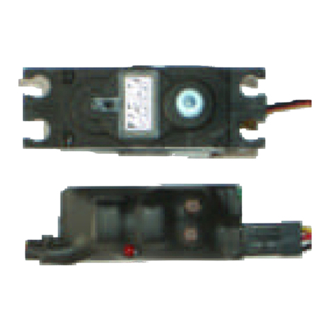
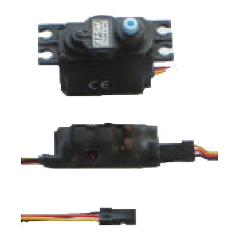
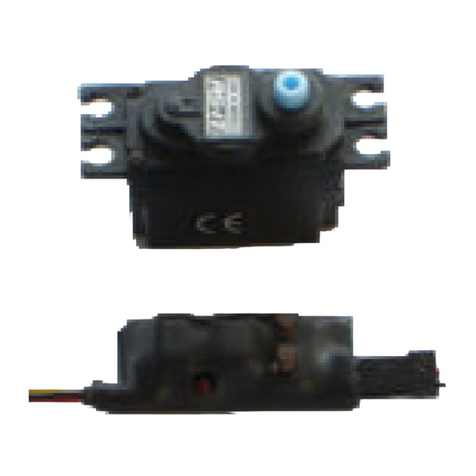
Timpdon Marine MRSS1 User manual

TimpdonMarine Tel 0161 -980 8054 Issue 1–May 2011
Web www.timpdon.co.uk
EMail marine@timpdon.co.uk
Features
•Switched control of a standard servo between two end points, at a
controlled rate. Can use any joystick or switched digital transmitter
channel.
•User programmable servo positions, with programmable rotation
speed.
•Can be re-programmed in-situ at any time, using built-in push button
switches.
•Programmed settings retained when power removed.
•Accommodates servo position and transmitter pulse widths in range 0.6
ms to 2.4 ms. Auto zero with centre neutral joysticks.
•Digital microprocessor controlled.
•Small size –45mm x 18mm x 12mm.
•Mounted inline between RC receiver and servo –powered from
receiver.
Timpdon
Marine Radio Servo Switch
Model MRSS1
Controlled rotation between
two servo positions.
Programmable servo
positions and rotation rate.
Inline adaptor -fitted
between RC receiver and
servo.
Powered from RC receiver.

TimpdonMarine Tel 0161 -980 8054 Issue 1–May 2011
Web www.timpdon.co.uk
EMail marine@timpdon.co.uk
Installation and Wiring
S2
S1
LED V+
Control
0V Red
Yellow
Black
Connector to Servo
MRSS1
Connector to
Radio Receiver
1Connect the flying lead to the selected channel of your radio receiver.
2Connect your servo to the 3 pin plug on the MRSS1, with the black
servo lead adjacent to edge of unit, and the yellow or white data lead
towards the middle.
3Power up the transmitter. Then power up the receiver.
4Check that, once the receiver has bound to the transmitter, the LED
on the MRSS1 illuminates continuously. This indicates that the
MRSS1 is receiving valid RC pulses. The MRSS1 has a in-built start
up delay of 4.5 seconds to permit binding. During this period, the LED
will flash.
5Check that, when you set the joystick to maximum, the servo
rotates at a controlled rate to the set position, when you set the
joystick to minimum, the servo rotates back to the reset position,
and when you set the joystick to the centre neutral position, there
is no change to the previous action.
6If, at any time, radio communication is lost, theLED will extinguish
and the servo will maintain its last setting. Once communication is re-
established, normal operation will start again automatically.
7Now program the MRSS1, as described below, for the required servo
positions and rotation rate for your system.
On completion of programming, the programmed settings will be
saved in non-volatile memory, and the system will automatically re-
boot in normal operation mode.
8Your system is now ready for use.

TimpdonMarine Tel 0161 -980 8054 Issue 1–May 2011
Web www.timpdon.co.uk
EMail marine@timpdon.co.uk
Principles of Operation
0.8 1.0 1.2 1.4 1.6 1.8 2.0 2.2
RC Pulse
Width in ms
Set
Reset
Auto-Zero
Limits of
Auto-Zero
0.2 ms 0.2ms
1In a standard RC system, the output from each receiver channel is a
variable width pulse, nominally between 1.0 ms and 2.0 ms in width,
repeated at intervals of approximately 20 ms. A pulse width of 1.0 ms
corresponds to the transmitter joystick at minimum, 2.0 ms to
maximum and 1.5 ms to centre.
2Within the MRSS1, the servo output is limited to one of two actions,
depending on the setting of the transmitter joystick:
Joystick Action
Maximum Rotate to programmed set position
Minimum Rotate to programmed reset position
The rotation rate of the servo, at all times, is constant.
3The servo output pulse widths corresponding to the maximum and
minimum joystick positions [set and reset] are user programmable,
as is the rotation rate of the servo between these positions. The
available range of servo output pulse widths is 0.6 ms to 2.4 ms.
4On power up, provided that the transmitter is on, the MRSS1 will auto
zero within an input pulse width range of 1.3 to 1.7 ms. The maximum
and minimum switch levels will then be set at +/-0.2 ms around the
auto zero position. The last valid auto zero setting is retained in non-
volatile memory.
If the transmitter is off at power up, or the pulse widths are outside the
permitted limits for auto zero, the unit will retain the last valid auto
zero level, if available, or set the zero position to 1.5 ms, if not.

TimpdonMarine Tel 0161 -980 8054 Issue 1–May 2011
Web www.timpdon.co.uk
EMail marine@timpdon.co.uk
Programming
Programming or re-programming may be performed at any time, using
push button switches S1 and S2, with indication provided by the LED.
Programming is performed in three steps, in order –Servo Reset
Position, Servo Set Position and Servo Rotation Rate
The set and reset limit positions of the servo may be set anywhere
within its operating range, subject to a limitation of RC pulse widths of
0.6 ms to 2.4 ms, as described above.
Programming Procedure
Programming may be undertaken with the transmitter either on or
off.
Press and hold both switches S1 and S2 together.
The LED will flash rapidly for about 5 seconds, and then go on
continuously. Then release both switches.
If you release either switch before the LED stops flashing, the
unit will remain in normal operation.
1You are now in Step 1 –Servo Reset Position
The LED will flash with single shortflashes, and the servo will move
to the current reset position.
Adjust the required reset position using either S1to increase the
servo position or S2to decrease it. The actual rotation direction is
servo dependent.
When satisfied, press and hold both switches S1 and S2 together.
The LED will flash rapidly for about 2 seconds, and then go on
continuously. Then release both switches.
If you release either switch before the LED stops flashing, the
unit will remain in program Step 1.
The unit will then proceed automatically proceed to program Step 2.

TimpdonMarine Tel 0161 -980 8054 Issue 1–May 2011
Web www.timpdon.co.uk
EMail marine@timpdon.co.uk
2You are now in Step 2 –Servo Set Position
The LED will flash with double shortflashes, and the servo will move
to the current set position.
Adjust the required set position using either S1to increase the servo
position or S2to decrease it. The actual rotation direction is servo
dependent.
When satisfied, press and hold both switches S1 and S2 together.
The LED will flash rapidly for about 2 seconds, and then go on
continuously. Then release both switches.
If you release either switch before the LED stops flashing, the
unit will remain in program Step 2.
The unit will then proceed automatically to program Step 3
3You are now in Step 3 –Servo Rotation Rate
The LED will flash with single long flashes, and the servo will rotate
continuously between the current set and reset positions at the
current rotation rate.
There are sixteen separate rotation rates, between 0.25 and 20
seconds for 90°rotation. Select the required rotation rate using
either S1to increase the rate or S2to decrease it. After the last step,
the rate will revert to the other end of the scale.
When satisfied, press and hold both switches S1 and S2 together.
The LED will flash rapidly for about 2 seconds, and then go on
continuously. Then release both switches.
If you release either switch before the LED stops flashing, the
unit will remain in program Step 3.
The unit will then save all programmed values to non-volatile
memory.
The LED will then flash rapidly for about 4 seconds to indicate
completion of programming, and then the MRSS1 will automatically
reboot in normal operation mode, with the new programmed settings
operational.
The MRSS1 is now ready for use.

TimpdonMarine Tel 0161 -980 8054 Issue 1–May 2011
Web www.timpdon.co.uk
EMail marine@timpdon.co.uk
Notes on Programming
1Once you have entered programming mode, there is no exit until all
programming steps have been completed. If you enter programming
mode inadvertently, and you do not wish to re-program the unit,
remove and re-apply power, to restart in normal operation mode.
2Remember that no new programmed settings are saved until the end
of programming Step 3. All steps must therefore be completed for
programming to be valid.
3If you make an error during programming, simply repeat the
programming procedure after the unit has re-booted in normal
operation mode.
Table of contents
Other Timpdon Marine Switch manuals
Popular Switch manuals by other brands
Avocent
Avocent SwitchView SC540 Quick installation guide

McDATA
McDATA Sphereon 4500 user manual
Aviosys
Aviosys IP POWER 9258T user manual
Briggs & Stratton
Briggs & Stratton 71020 Illustrated parts list
Intermatic
Intermatic T175CR supplementary guide
ZyXEL Communications
ZyXEL Communications GS1100-16 - EDITION 1 Specifications
